Unit - 3
Design Of Water Treatment Plant
- The word has been derived from a Latin word 'flocculator', it means, to form a floc.
Flocculation is stimulation by mechanical methods to collect destabilized particles into compact flocs.
- When these particles come in contact, they become large and get settled in the form of flocs.
- The flocculation is the result of changes in the velocity of the water which is mixed with coagulant.
- Coagulation means to add the chemicals, called as coagulant, which react with the impurities and convert them it to sizable and settleable volumes.
- Generally, in a case of the public water supply project; the source of water is the surface water.
- This water as it remains open, has a lot of impurities in the suspended form making it turbid.
- Sometimes the colour of the water also is changed due to colloidal matter and the dissolved organic material. So, it has a turbidity due to clay, silt and some organic matter.
- Unless, such water is allowed to settle down for a longer period in the sedimentation tank, these impurities are not removed, or it can be done by making the size of the suspended water larger and bigger; to allow it to settle down.
- Coagulation means to add the chemicals, called as coagulant, which react with the impurities and convert them it to sizable and settleable volumes.
- This method of coagulation is used when the turbidity of water is more than 40 p.p.m. (parts per million).
- One must know that coagulation is not, complete method of water purification. It helps to remove the impurities, when used in the plain sedimentation. It is necessary to follow the methods of filtration for the final removal of the impurities to make it safe and portable.
Key Takeaways:
- Coagulation means to add the chemicals, called as coagulant, which react with the impurities and convert them it to sizable and settleable volumes.
- The base of the process of coagulation is that the stability of colloidal particles depends upon the electric charge which they have or they possess.
- The primary charge of the colloidal particle is due to the charged groups, which are within the surface of the particles or may be due to the process of adsorption of the layer of ions, from the surrounding medium.
- This primary charge gets counter balanced by the ions of opposite charge in the water phase.
- Between the water and the solid an electrical double layer is formed at the interface.
- The double layer has,
(i) The charged colloidal Particles.
(ii) The equivalent excess of oppositely charged counter ions they get accumulate in the water, near the surface of the particles.
- The counter ions are attracted electro-statically to the particle surface and they cause the high concentration at the particle surface.
- This diffusion or decrease of these counter ions, is due to the agitation and also due to replacement by other ions.
- When there is a high concentration of counter ions, in the water the diffused layer is compacted. It is known as the diffused double layer theory.
- Common coagulants alum and ferric salt:
- Alum:
It is also called as 'Aluminium sulphate'. Its use in the water treatment plant is almost worldwide. It is supply in the form of flakes or in the form of solid lumps and while applying for the treatment, it is converted into a solution.
a) Advantages of Alum
- It helps to reduce the bad odour, taste and also reduces the turbidity of the water.
- The price of Alum is low.
- The use of Alum does not require skill full workers to handle so the cost goes still low.
- Alum, after its reaction, creates almost crystal clear water.
- The floc formed by Alum, is very tough and does not break easily.
- The dosage of Alum depends upon the turbidity of water, pH value, temperature of water, colour and taste of water etc. The range of Alum requirement for the treatment varies between 5 and 30 milligrams per lit.
- For the normal conditions of water, the dosage is about 14 milligrams per lit.
(b) Disadvantages of Alum
- The sludge developed after the use of Alum is difficult to dispose off. It is also has been observed that this sludge cannot be used for filling the low-lying areas.
- To maintain the pH value, together with alum, caustic soda or the lime is required to be added.
- This increases the cost of the process.
2. Ferric Salts:
- The effective PH range is 8.50 and above.
- If floc is heavier than the floc formed by the alum.
Common coagulant alum:
- The generally used steel coagulants fall into fashionable categories: the ones primarily based totally on aluminum and people primarily based totally on iron. The aluminum coagulants consist of aluminum sulfate, aluminum chloride and sodium aluminate.
- The iron coagulants consist of ferric sulfate, ferrous sulfate, ferric chloride and ferric chloride sulfate. Other chemical substances used as coagulants consist of hydrated lime and magnesium carbonate. The effectiveness of aluminum and iron coagulants arises basically from their capacity to shape multi-charged polynuclear complexes with stronger adsorption characteristics. The nature of the complexes fashioned can be managed with the aid of using the pH of the system. When steel coagulants are brought to water the steel ions (Al and Fe) hydrolyze swiftly however in an extremely out of control manner, forming a sequence of steel hydrolysis species.
- The performance of speedy mixing, the pH, and the coagulant dosage decide which hydrolysis species is powerful for treatment. There has been good sized improvement of pre-hydrolyzed inorganic coagulants, primarily based totally on each aluminum and iron to provide an appropriate hydrolysis species irrespective of the technique situations for the duration of treatment. These consist of aluminum chlorohydrate, polyaluminum chloride, polyaluminum sulfate chloride, polyaluminum silicate chloride and varieties of polyaluminum chloride with natural polymers. Iron paperwork consist of polyferric sulfate and ferric salts with polymers. There also are polymerized aluminum-iron blends.
Ferric salts:
- The number one use of ferric chloride is to get rid of impurities in water and for wastewater remedy. Ferric chloride is likewise one of the few water remedy chemical substances which could sequester odors. Combined with use in commercial water programs and withinside the pretreatment of seawater previous to desalination, general water remedy bills for extra than three-fourths of general call for globally.
- Smaller volumes of higher-grade ferric chloride are used as a catalyst in chemical reactions and as an etchant in microelectronics production (revealed circuit boards [PCBs]). The PCB marketplace is essentially in Asia. In industrialized regions (United States, Western Europe, and Japan), ferric chloride markets are especially mature.
- Although it's far identified as a noticeably powerful flocculant and sequestering agent for sludge and smell control, substitution from competing merchandise will result in especially flat call for. In Asia and the Middle East, wherein financial and populace enlargement has ended in more call for water management, ferric chloride keeps to revel in above-common boom.
- For international locations in Central and Eastern Europe, that have generally finished their compliance with EU guidelines in view that becoming a member of the European Union, boom is probable to be slower. Many international locations in Latin America were sluggish to put money into infrastructure or undertake essential environmental and fitness legislation, however that is predicted to alternate because the economies withinside the area get over current recessions.
Key Takeaways:
- Alum, after its reaction, creates almost crystal clear water.
Bentonite clay:
- The goal of this paintings is to look at the effectiveness of bentonite as a coagulation adjuvant on water remedy excellent at Ait Baha station. In our case, bentonite is used as a supply of turbidity and isn't an adsorbent.
- Jar exams have been done on uncooked water samples of low turbidity in keeping with the technique implemented withinside the laboratory. The overall performance of the bentonite became examined in mixtures: uncooked water/bentonite, uncooked water/coagulant and coagulant/bentonite.
- The most important targets of this have a look at are to confirm whether or not bentonite acts as a coagulation resource for water remedy, after which to limit the dose of aluminum sulfate at the same time as respecting the remedy yield of the station. Indeed, the outcomes received confirmed that the addition of bentonite doses of 20 mg/L can put off 96.72% of the turbidity and 60% of the oxidizable material.
- Also, the boom of the dose of bentonite decreases the pH extra than using aluminum sulfate alone, which makes the water pH ultimate for coagulation–flocculation, however additionally to enhance the coagulation and flocculation strategies to attain an awesome excellent effluent and the speedy sedimentation of the flocs formed.
Lime stone:
- Lime is utilized by many municipalities to enhance water quality, mainly for water softening and arsenic removal. Indeed, the American Water Works Association has issued requirements that offer for the usage of lime in ingesting water remedy. Softening - In water softening, hydrated lime is used to eliminate carbonate "hardness" from the water.
- Hardness as a result of different calcium and magnesium salts, referred to as noncarbonate hardness, is typically dealt with via the lime-soda process, which includes the precipitation of magnesium by means of lime.
- The co-produced calcium salt reacts with the soda ash to shape a calcium-carbonate precipitate. Lime-better softening also can be used to eliminate arsenic from water.
- Stricter ingesting water guidelines for arsenic have improved the want for this remedy. PH Adjustment/Coagulation - Hydrated lime is extensively used to modify the pH of water to put together it for similarly remedy. Lime is likewise used to combat "pink water" by means of neutralizing the acid water, thereby lowering corrosion of pipes and mains from acid waters.
- The corrosive waters incorporate immoderate quantities of carbon dioxide. Lime precipitates the CO2 to shape calcium carbonate, which gives a protecting coating at the inner of water mains. Lime is used alongside alum or iron salts for coagulating suspended solids with a view to eliminate turbidity from water. It serves to keep the right pH for maximum great coagulation conditions.
- In a few water-remedy plants, alum sludge is dealt with lime to facilitate sludge thickening on strain filters. Effect on Pathogen Growth - By elevating the pH of water to 10.5-eleven thru the addition of lime and maintaining the water in touch with lime for 24-seventy-two hours, lime controls the surroundings required for the increase of microorganism and positive viruses.
- This software of lime is applied where "phenolic water" exists, due to the fact chlorine remedy has a tendency to supply unpalatable water because of the presence of phenol. This process, referred to as 'extra alkalinity remedy', additionally eliminates maximum heavy metals. Removal of Impurities - One of the maximum not unusual place techniques of getting rid of silica from water includes the usage of dolomitic lime.
- The magnesium factor of this lime is the lively constituent in silica removal. Lime is likewise used to eliminate manganese, fluoride, natural tannins and iron from water supplies.
Silicate:
- Four experiments of coagulation and flocculation had been performed to analyze the traits of colloidal silica elimination in a high-tech commercial wastewater remedy plant for reclamation and reuse of the effluent. Experimental consequences illustrated that poly-aluminium chloride (PACl) confirmed better performances on colloidal silica elimination than alum.
- Interestingly, the 2 coagulants tested the identical capability on silica elimination. The unique silica elimination capability changed into about 0.one hundred thirty-five mg SiO2/mg Al2O3 while the dosage of coagulants changed into withinside the variety 30-one hundred fifty mg/L Al2O3. In addition, the silica changed into decreased substantially on the circumstance of pH above 8.
- Experimental information implied that precipitation of aluminium flocs changed into the predominant mechanism for colloid silica elimination in PACl and alum coagulation, besides, fee adsorption changed into additionally essential for enhancing elimination efficiency.
- Moreover, the addition of polyacrylic acid (PAA) as a flocculant may want to barely develop silica elimination withinside the PACl coagulation. The blended PACl/PAA/flocs coagulation changed into powerful for the elimination of colloidal silica, soluble COD, and turbidity and additionally appropriate as a pretreatment unit in wastewater reclamation and reuse processes.
Polyelecrtolytes:
- They are the polymers and on the basis of the charge they carry, they can be classified as anionic, cationic, and non-ionic. Among these only cationic polyelectrolytes can be used very effectively as the independent coagulant. While in cases of other varieties, they can be used together with Alum or any other conventional coagulants.
- In India polyelectrolytes are collected from the extract of Nirmali seeds. This type of deciduous plant, small in size is found in almost all the state in India but mainly in Andhra Pradesh, Konkan coastal region of Maharashtra State, Madhya Pradesh, Orissa and in West Bengal.
- The use of polyelectrolytes needs to have a skilled supervision because if the dose is more than required, it may affect the working of filters.
- We must note here that the use of these polyelectrolytes as the coagulants is still in the pilot stage and so they may prove to be a better alternative for other coagulants in future.
Key Takeaways:
- Hardness as a result of different calcium and magnesium salts, referred to as noncarbonate hardness, is typically dealt with via the lime-soda process, which includes the precipitation of magnesium by means of lime.
- In the past, the natural coagulants of vegetable and of marine origin, were used for the water and also for wasted water treatment, before the synthetic chemical such as Alum and ferric salts, were introduced. Without any scientific reasoning the natural coagulants were discouraged.
- Now, a number of effective natural coagulants have been identified from the plants. For example, Moringa, Nirmali, Okra, Apricot, Beans, Rice, Maize etc. This use of natural coagulant has helped to reduce the cost of water treatment.
- Moringa Oleifera (M.O.) is widely used in most of the developing countries. It has the following advantages:
- It has good coagulation property without the constrains of alum.
- The sludge produced by M.O. Is very compact (about 4 to 5 times, compact, then produced by alum).
- The efficiency to remove turbidity is about 95%.
- M.O. Is cheaper coagulant.
Concept of mean velocity gradient:
- The velocity gradient of two fluid particles which are 0.05 feet apart, with relative velocity of 0.2 fps is equal to, 2fps / 0.05 ft = 40fps / f t
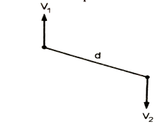
Fig. 1: Mean Velocity
- The rate of particle collision α G
- Shear force α 4
- Total number of particle collision α GT
- The power consumption in the process depends upon the speed of mixing the amount coagulants to be mixed and the volume of water.
Power consumption:
- If you need to training session how an awful lot power an equipment makes use of in a day, then all you need to do is multiply the device's wattage via way of means of the wide variety of hours you operate it.
Introduction:
- The word has been derived from a Latin word 'flocculator', it means, to form a floc.
- Flocculation is stimulation by mechanical methods to collect destabilized particles into compact flocs.
- When these particles come in contact, they become large and get settled in the form of flocs.
- The flocculation is the result of changes in the velocity of the water which is mixed with coagulant.
- This process takes place in the mixing basin also known as flocculation basin.
- It is common practice to provide the flash or rapid mix which is followed by the slow mixing.
Design of flocculator:
- See the Fig. which shows the design of a typical flocculator. In this the slow mixing is achieved by rotating the paddles with two to three revolutions per minute.
- Sometimes the flocculator is combined with the sedimentation tank. This type of tank is known as coagulation sedimentation tank.
- A floc chamber is attached before the water enters in the sedimentation tank the period of detention in the floc chamber is about 15 to 40 minutes and detention period for the tank is about 3 to 4 hours. The cleaning of the tank is carried out after 3 to 6 months.
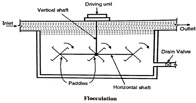
Fig. 2: Flocculator
Important terms- Design of flocculator:
- Detention period
"It is the period of time given to settle the row water to settle down the impurities".
2. Discrete particles
"It is size shape of the particles which varies between  and
and  cm”
cm”
3. Surface loading
"It is process of mixing the chemicals for the precipitation of impurities".
4. Mean velocity gradient
"It is the rate of change of velocity per unit distance normal to a section i.e., meter sec. Metre". So, G (Gradient) is expressed as sec
5. Weir loading
If the water falls over a weir, through same out let it is called as weir loading. It is expressed as "The quantity of water discharged per day or per hour, per unit length of the weir.
6. Flocculation
It is the result of changes in the velocity of the water which is mixed with coagulant.
7. Surface overflow rate
"Surface overflow or surface loading is the quantity of water i.e., volume of water passing per day or per hour, per unit horizontal area."
Design criteria for flocculator provided with rotating paddles:
- Following are the various design criteria commonly involved in the design of flocculator:
- Depth of tank is taken from 3m to 4.5 m.
2. Detention time is considered as 10 minutes to 40 minutes and normal detention time is taken as 30 minutes.
3. Length to width ratio is considered as 2 to 3 for rectangular type of basin.
4. Mean velocity gradient (G),
G =
Where, G = Mean velocity gradient (sec¹)
P = Power dissipated in 'watt'.
μ = Absolute viscosity (N-s/m²)
V = Volume to which power is applied (m³).
- The flocculation technique most commonly used mechanical agitation with rotating paddle wheels or vertically mounted turbines:
P = Power input by the impeller
= 
Where  = Coefficient of drug of paddle
= 1.8 for paddle with flat paddles
 = Relative velocity of impeller and fluid
 = Velocity of the tip of the paddles
V = Velocity of water adjacent to the tip of the paddle
The optimum value of G can be determined
Key Takeaways:
- The flocculation is the result of changes in the velocity of the water which is mixed with coagulant.
Following are the various steps involved in the design of clariflocculator:
D, be the diameter of clariflocculator and D, be the diameter of flocculator.
Flocculator design
- Detention time, discharge (Q) in m'/min are considered.
- Volume of flocculator chamber = Q x detention time
- Assume depth of flocculation zone.
- Surface area of tank
 =
= 
- Find D₂ i.e., diameter of flocculator provide control chamber for flocculator of diameter 'D₂'
Clariflocculator design
1. For given discharge Q in m3/min and detention time find volume
Volume = Qx detention time
2. For a given surface loading, find the area of tank.
Area of tank = 
3. Find clarifier surface area (in ring form)
 = Area of tank
4. Find depth
Depth =
5. Find the overall depth by providing additional depth for sludge and for free board.
Introduction
- Even after the process of sedimentation and the process of coagulation which removes the impurities present in the water, the water still is not fully pure for consumption as it may still have some very micro particles or some fine micro-organic matter.
- To remove these fine particles from the water, the water is allowed to pass through the beds of granular material. This process is known as filtration.
- After this process of filtration, the water becomes free from all the undesirable impurities such as colour, odour, turbidity and also the pathogenic bacteria.
- In the process of purification of water, the filtration is the most important stage. The water is allowed to pass through a thick layer of sand to remove all the remaining impurities of water to make it portable and to make it safe for drinking purpose. This process brings following changes in the water, which is getting treated.
- The suspended and colloidal impurities are removed from the water, to a great extent.
- The chemical characteristics of the water get changed.
- The proportion of bacteria in the water is reduced.
- These changes are the results of the four actions which take place during the process of filtration. They are as follows:
Filtration Process
- Mechanical straining
- Sedimentation
- Biological metabolism
- Electrolytic changes
Let us study the functions of these actions in process of filtration.
- Mechanical straining
- The suspended particles which cannot pass through the sand, are trapped and are removed by this action.
2. Sedimentation
- The void between the sand particles acts as a small size sedimentation tank and the impurities are arrested either due to coating developed on the sand particles by the colloidal matter saturated on the sand or by the physical attraction between two particles of any matter.
3. Biological metabolism
- The life process of any living cell is called as biological metabolism. When any type of bacteria is caught in the voids of the sand particles a thin jell or a film is developed around the particles of sand having a very large number of bacteria which use the organic impurities as a food and convert them into harmless compounds to make the water safe for drinking.
4. Electrolytic changes
- When any two deflect particles have opposite electric charges are put together, the electrical charges are totally neutralized to develop a new chemical substance which is not harmful. They are needed to be removed by cleaning the filters to make it safe and portable.
Key Takeaways:
- The suspended and colloidal impurities are removed from the water, to a great extent.
- Base materials:
- The base material of gravel is placed on the top of the under-drainage system. The depth of the gravel material varies between 300 mm and 750 mm. The size of the gravel’s changes from the top to the bottom layer e.g., the top layer has the gravels having the size between 3mm and 6mm.
- In the intermediate layer, the size varies between 6 mm and 20 mm (in some cases it may have the size of the gravel between 20 mm and 40 mm). While in the lowest i.e., bottom layer.
- The size of gravel varies between 40 mm and 65 mm.
Out of the total depth of the base material of gravel the top layer is about 150 mm, in depth, the middle or the intermediate layers.
- Cover 150+ 150 mm deep and bottom layer also is 150 mm deep. So, the total depth of these layers is 600 mm.
2. Filter media of sand:
- Above the layers of grave a layer of sand is placed.
- The depth of this sand layer varies between 600 mm and 900 mm and size of the sand particles also varies from 0.20 mm to 0.30 mm.
- Fine sand can be more effective to remove the impurities but the time required for the process is long and processes is slow.
Rapid sand filter:
- Though the slow sand filter has a lot of advantages and good for the rural water treatment plant, the greatest disadvantage of the slow sand filter is that it needs to have a large space of its installation (in the rural areas, space is not a major problem).
- So, in the urban areas where the land cost is sky hill, that method becomes useless e.g., for a moderately populated town say about 15000, the area required for the installation of the slow sand filter plant is about 1000 m², and considering the future water demand and the space required for other attached equipment for water purification, about 2000 m² would be necessary.
- So, it would be too costly to follow the slow sand filtration method. So, the rapid sand filtration method has been put to use.
- Methods of Rapid Filtration
- The rate of filtration can be increased by using two different methods, such as
It can be achieved as increasing the size of the sand particles. This reduces the friction of sand particles with the moving water. This helps to gain high speed for the filtration.
- If the water allowed to pass through the sand, with pressure, its velocity increases and so the time required for filtration is reduced.
B. Design of the Rapid Sand Filters
- As shown in the Fig. It has five essential parts such as enclosure tank, under drainage system, base material, filter media of sand and appurtenances. Let us study the functioning of these parts.
1.Enclosure tank
- By using either of masonry or concrete a water-tight tank is constructed. The floor and sides of the tank also are made water tight by using water proofing material. 2 With the surface area of the tank varies between 10 m² and 50 m² and the depth between 2.50 m and 3.50 m. These units are arranged in series.
2.Under drainage system
- There are various types of under drainage systems, but among them the commonly used systems are as follows Let us see the functioning of these two under drainage systems.
(i) Perforated pipe system
- In this system, various lateral drains are attached to the central drain. These drains are made up of cast-iron. They are placed with the average distance between 150 mm and 300 mm. The pipes of the drains have holes with 10 mm diameter and having the angle of 30° between two holes. To control the rusting of the holes, brass bushings are used to protect the holes.
- This system of perforated pipe is very simple and need less cost also but it requires about 700 lits. Of water per minute - per m² of the filter area for the washing purpose.
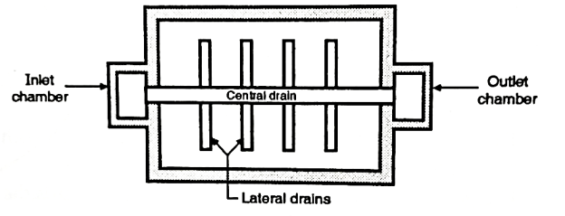
Fig. 3: Perforated pipe system
(iii) Pipe and strainer system
- In this system also, there is a central drain system but instead of wholes, this system has strainers. It is a small pipe made of brass. It has holes on its surface but it is closed at the top. They are fixed on the top of the drain. A compressed air is used for washing the filters. It needs about 250 litres of water per minute per m² of the filter area, for washing. It is called as low velocity wash.
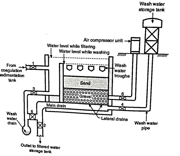
Fig. 4: Pipe and strainer system
3. Base material
- On the top of the under-drainage system, the base material i.e., gravel is placed. The size of the gravel varies between 3 mm and 6 mm in the top layer to 20 mm to 40 mm in the lowest level. The total depth of the gravel is about 600 mm.
4. Filter media of sand
- Above the layers of gravel, the sand is placed. The depth of sand layers varies between 600 mm and 900 mm. The size of the sand particles varies between 0.35 mm and 60 mm. As the space of voids increases, the rate of filtration increases.
5. Appurtenances
- Together with the usual appurtenances used in slow sand filters, additional devices are provided for fast sand filtration e.g., air compressor, wash-water troughs and venturi rate controller.
6. The initial and final head loss
- In case of rapid sand filters, the initial head loss is 30 cm and final head loss is 3 meters. In case of slow and filters it is 15 cm and 100 cm respectively.
Key Takeaways:
- The rate of filtration can be increased by using two different methods, such as
It can be achieved as increasing the size of the sand particles. This reduces the friction of sand particles with the moving water. This helps to gain high speed for the filtration.
Following are the various design criteria to be broadly considered in the design of rapid sand filter.
1. Rate of filtration 'Q'
 = Bi x 29323 ………Hudson formula
Where,
Q = Rate of filtration in m³/m²/h
d = Size of sand in 'mm'.
L = depth of sand bed in 'm'
h = terminal head loss in 'm'
Bi= break through index
(The value of Bi depends upon the response to coagulation and degree of pre-treatment in filter influent.)
Design range of Bi is in between 
Rate of filtration is 75-(100-150)-200 litres /m²/minute
N= Number of filter unit
=  ……… Qis in
 / hr
/ hr
2. Size of filter bed in which surface area should be between 8- (10-20)-40 m² and length (L) to breadth (B) ratio should range from 1.25 to 1.33.
 25 to 1.33
3. Depth of filter sand media should range from 60 cm to 90 cm.
The depth of sand can be checked against breakthrough of flow through sand bed by determining the minimum depth required by Hudson formula.
Depth of filter sand media depends on the following parameter:
(i) Rate of filtration
(ii) Break through index (Bi) for the given size of filter sand.
(iii) Quantity of water to be filtered.
(iv) Minimum depth of filter sand obtained from Hudson formula.
Minimum depth of sand (/) in 'm' can be calculated from Hudson formula
 = Bi x 29323 .... Hudson formula
L= 
Q = Filtration rate in m /hr square meter area of filter
d = sand size in 'mm'
h = Terminal head loss in m
Bi = Break through index 
4. Depth of base material (gravel) should range from 45 cm to 60 cm well graded. Gravel should be free from any dirt, clay, organic matter and must be hard durable and round
Sand specifications should have the following sizes.
(i) Maximum size is 1 mm
(ii) Minimum size is 0.45 mm
(iii) Effective size ranges from 0.45 mm to 0.70 mm
(iv) Uniform coefficient = 1.3 - (1.5) - 1.7
5. Depth of water over sand should range from 1m to 2m. 8. In order to check gravel, upset due to localized high velocity during backwash, a 6 cm to 8cm thick layer of garnet is placed at the top of gravel bed.
6. Requisite depth (1) in cm of a component gravel layer of size d in mm can be calculated from the following empirical expression.
l = 2.54K * (log d)
Where, I = requisite depth in cm
d = gravel layer size in mm
K = Constant varies from 10 to 14
Introduction
- In pressure filters are closed vessels. The coagulated raw water is admitted, under pressure, in the vessel, this pressure is more than that of the atmospheric pressure. These vessels, so must be air-tight. By using the pumps, the water is admitted in the vessel. The pressure developed ranges between 3 and 7 kg/cm².
- These filters have two different shapes i.e., horizontal or vertical. The steel cylinders are used as the pressure vessels which are either welded or are rivetted. The diameters vary between 1.5 and 3 metres.
- The length or height (depending upon the shape) varies between 3.5 and 8 metres Near the top, the inspection windows are provided. For cleaning and operation various types of valves are provided.
They have gravels as the base material and the sand is provided as filter media. The thickness of sand-bed varies between 45 and 60 cm; the effective size of sand is 0.5 and the uniformity coefficient of sand is 1.5. The filtration rate varies between 6000 and 15000 lu/hrs/sq metre of the filter media.
- The working these filters is like the rapid sand filters. They need frequent cleaning, for better results.
A- Row water inlet valve
B- B-Wash water inlet valve
C-Filtered water valve
D-Wash water drain valve
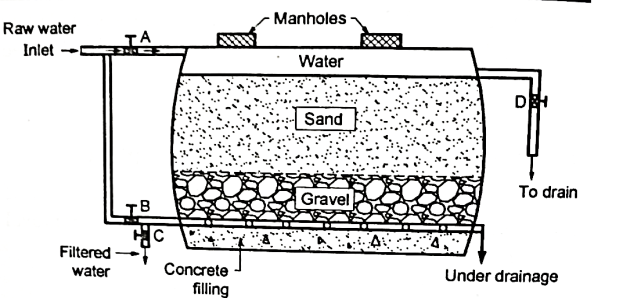
Fig. 5: Pressure filter
Suitability of Pressure Filters
- These filters are not suitable for the public water supply schemes but still they can be used for colonier, swimming pools, industrial plants, bus stations or railway stations etc.
- They are not very efficient for removing bacteria or turbidity, if compared with the rapid gravity filters.
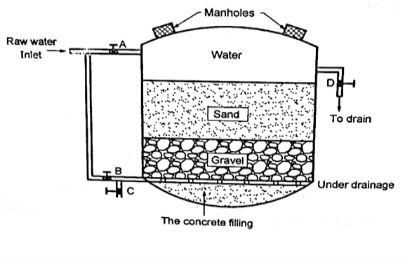
Fig. 6: Pressure filter
- The Multi or Dual media filtration is used mainly to remove the turbidity and the suspended particles.
- For that Anthracite (coal) + Sand filters are used.
- This type of filter provides very efficient removal of particles with high filtration rate. It can be used for a long period of time before the backwash is required.
- It has the graded beds of sand and anthracite.
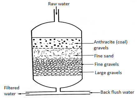
Fig. 7: Multimedia and dual media filter
Following are the various rules to be followed in designing the under-drainage system.
1. Ratio of length to diameter of lateral should not be more than 60.
2. Diameter of perforations i.e., diameters of holes in the laterals 5 mm to 12 mm.
3. Spacing of perforations varies from 8 cm to 20 cm, 8 cm for 5 mm holes and 20 cm for 12 mm perforations or holes.
4. is not greater than 0.5 for 12 mm holes.
5.  = 0.002 to 0.003
6. Spacing of lateral should be 30 cm for satisfactory diffusion, however limited to total available head.
7. Cross-sectional area of manifold must be 1.5 to 2 times the total cross-sectional area of laterals.
Following are the various design criteria to be followed in the design of wash water trough or gutter:
1. The trough should be large enough to carry all the water delivered to it with a free board of 60 mm to 80mm.
2.The bottom of the trough is kept at least 50 mm above the top level of sand.
3. Horizontal travel of dirty water on the surface of filter should not be greater than 0.5m to 1.0m before reaching to trough or gutter.
4. The spacing of wash water troughs is kept between 1.5m to 2m.
5. For fixing the size of the trough (gutter) with a level bottom, the following relation is used.
Q = 
Where, Q = Total water received by the gutter in m'/sec.
b = Width of trough or gutter in 'm'.
y= Depth of water at the upper end of the trough in 'm'.
6. Troughs are made in C.1, fibre glass, reinforced plastics or other corrosion resisting material generally, R.C.C. Troughs are being used in practice.
Back washing of rapid sand gravity filter
- The backwashing refers to pumping water backwards, through the filter media. If required, the compressed air is also used, during this process.
The backwashing a general form of a preventive maintenance which allows the reuse of the filter media.
- This system can be an automated process, which is run by local.
Programmable Logical controllers (PLCs): This system is triggered after a set of time internal. Generally, when the filter effluent turbidity is greater than the treatment guideline, the PLCs starts.
- Even when the differential pressure i.e., the head loss across the filter exceeds. A set value the PLCs starts. So. Back washing is helpful step, to maintain the quality of the process.
Key Takeaways:
- In pressure filters are closed vessels. The coagulated raw water is admitted, under pressure, in the vessel, this pressure is more than that of the atmospheric pressure. These vessels, so must be air-tight. By using the pumps, the water is admitted in the vessel. The pressure developed ranges between 3 and 7 kg/cm².
Introduction
While using the filters for removed of the unwanted materials from the water to be used for consumption following problems i.e., troubles may occur.
(a) Air binding
- Due to the frictional resistance of sand the water which passes through the filters loses its head. In the beginning the head losses are about is 15 to 25 cm but after a prolonged use of filters the friction goes on increasing as the impurities go on saturating in the sand the losses go an increasing. At that time a negative pressure is developed. It reduces the speed of filtration and finally the working of filtration is totally stopped.
(b) Mud ball formation
- The coagulated particles finally get accumulated and they form the mud ball they have size of about 2 to 5. Cm diameter. These muds get sunk into the sand and affect the process of filtration.
(c) Cracking of filter bed
- The cracking process develops in the top layer. Due to the entry of entrapping of earthy particles. After some period of time these earthy particles shrink and cause cracks in the bed of the sand. They are generally associated with the junctions. This way, the dirty material enters into the gravel level and affects the working of filters.
(d) Sand incrustation
- Due to the accumulation of sticky material in the water the sand particles came together and their size increases and so the process of filtration is affected.
(e) Jetting and sand boils
- It happens during the process of backwashing. These backwashing of water causes lifting the gravels and sand in the upward direction, which causes sand boiling. This can be reduced by surface wash.
(f) Sand Leakage
- The downward movement of fibre sand or the sand leakage stairs when the top layer of gravel is displaced by the back wash process. This also affects the process of filtration.
Design of rapid sand gravity filter:
- Rate of filtration 'Q'
 = Bi x 29323 ………Hudson formula
Where,
Q = Rate of filtration in m³/m²/h
d = Size of sand in 'mm'.
L = depth of sand bed in 'm'
h = terminal head loss in 'm'
Bi= break through index
(The value of Bi depends upon the response to coagulation and degree of pre-treatment in filter influent.)
Design range of Bi is in between 
Rate of filtration is 75-(100-150)-200 litres /m²/minute
N= Number of filter unit
=  ……… Qis in
 / hr
/ hr
2. Size of filter bed in which surface area should be between 8- (10-20)-40 m² and length (L) to breadth (B) ratio should range from 1.25 to 1.33.
 25 to 1.33
3. Depth of filter sand media should range from 60 cm to 90 cm.
The depth of sand can be checked against breakthrough of flow through sand bed by determining the minimum depth required by Hudson formula.
Depth of filter sand media depends on the following parameter:
(i) Rate of filtration
(ii) Break through index (Bi) for the given size of filter sand.
(iii) Quantity of water to be filtered.
(iv) Minimum depth of filter sand obtained from Hudson formula.
Minimum depth of sand (/) in 'm' can be calculated from Hudson formula
 = Bi x 29323 .... Hudson formula
L= 
Q = Filtration rate in m /hr square meter area of filter
d = sand size in 'mm'
h = Terminal head loss in m
Bi = Break through index 
4. Depth of base material (gravel) should range from 45 cm to 60 cm well graded. Gravel should be free from any dirt, clay, organic matter and must be hard durable and round
Sand specifications should have the following sizes.
(i) Maximum size is 1 mm
(ii) Minimum size is 0.45 mm
(iii) Effective size ranges from 0.45 mm to 0.70 mm
(iv) Uniform coefficient = 1.3 - (1.5) - 1.7
5. Depth of water over sand should range from 1m to 2m. 8. In order to check gravel upset due to localized high velocity during backwash, a 6 cm to 8cm thick layer of garnet is placed at the top of gravel bed.
6. Requisite depth (1) in cm of a component gravel layer of size d in mm can be calculated from the following empirical expression.
l = 2.54K * (log d)
Where, I = requisite depth in cm
d = gravel layer size in mm
K = Constant varies from 10 to 14
Key Takeaways:
- The coagulated particles finally get accumulated and they form the mud ball they have size of about 2 to 5. Cm diameter. These muds get sunk into the sand and affect the process of filtration.
References:
- Environmental Engineering, Peavy and Rowe, McGraw Hill Publication
- Optimal Design of Water Distribution Networks, P.R. Bhave, Narosa Publishing House
- Rain Water Harvesting: Making water Every Body’s business, vcentre for science and Environment
- Environmental Remote sensing from Regional to global Scales, Ed. Giles Foody, Wiley
- Water supply Engineering, Harold FatonBabbit& James Joseph Doland, Tata McGraw Hill
- Environmental Engineering Laboratory Manual and Dr. N. Kumarswamy. NEERI, Nagpur