UNIT-1
GRAPHIC PRIMITIVES AND SCAN CONVERSION ALGORITHM
The more complex objects and operations are constructed by the primitives that are low level objects or the operations from higher level.
The primitives are the basic elements used in computer graphics.
Lines, curves and polygons are the basic elements that are used to create complex graphical images in computer.
The operations of basic primitives are used in programing language.
To create any drawing in computer this primitiveis used as software.
To store the type of display the data is important.
Following are the graphics primitives which are form together to create complex images in computer.
Graphics is made by this basic elementthat are used to create graphics application.
The most basic element of structure is pixel that is short of picture element.
Pixel:
It is a building block of graphics.
A pixel is the point of light or it is just a tiny dot on raster display.
Line:
The line is the especial build block of graphics it is used in various platform such as line graphs, bar and pie chart, 2D and 3D graphs in mathematical function, engineering drawing and architectural plans.
The straight line is developed in two ways as structural method which shows the pixels that should be set before drawing line and conditional method that is used to find the pixels which should be set next.
Resolution
A resolution of 100 dots line per inch has the dot size of 0.01 inch.
The resolution of CRT is related to the dot size.
Aspect ratio
The ratio of the distance between the center of two adjacent horizontal pixel to that of the vertical pixel is known as aspect ratio that is used in line generation algorithms.
Frame Buffer
The frame buffer is the video output device which drives a video display from the memory buffer as complete set of data.
The images are stored in terms of pixel by pixel.
The memory cane be disc, integrated circuits, etc.
The display device is an output device which is used to represent the information in the form of images.
It is also known as the video monitor or video display unit (VDU).
This deviceis designed to display, view, model or display information.
The main advantage of displaying is the sharing of information.
There are some display devices given below.
1.3.1 Cathode ray tube (CRT)
It is a traditional computer monitor and television.
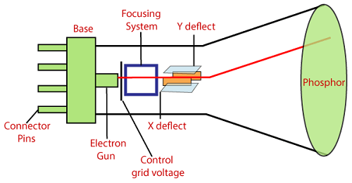
It a particular type of vacuum tube that displays images when an electron beam collides on the radiant surface.
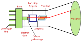
Following are the elements of the CRT.
Electron gun: it is focused on narrow beam facing the CRT
Focusing and accelerating anodes: Used to produce a narrow and sharply focused beam of electrons.
Horizontal and vertical deflection plates: used to guide the path of the electron beam which produces the electromagnetic field that bends the electron beam through the area as it travels.
Phosphorus coated screen: used to produce bright spots when the high velocity electron beam hits it
1.3.2 Color CRT Monitor
It is same as CRT monitor.
It is basically used to combine three colors that is red, green and blue.
By using these three colors we can create millions on different colors.
There are two basic color display producing techniques are given below:
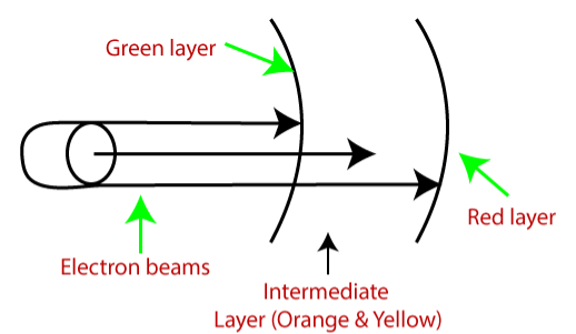
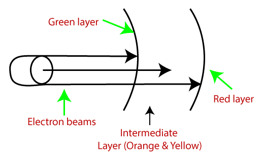
a) Beam Penetration Method:
It is used with a random scan monitor for displaying picture.
In this there are two phosphorus layers that are red and green which are coated inside the screen.
The colors are depending on how far the electron beam penetrates the phosphorus surface.
b) Shadow Mask Method:
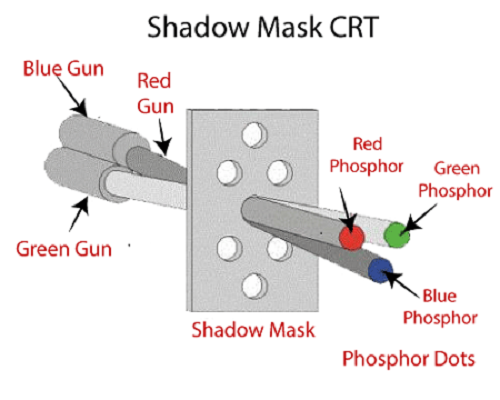
It is used with raster scan monitor for displaying pictures.
It has more range of color than beam penetration method.
It is used in television sets and monitor.
It has three phosphorus color dots at each position of the pixel.
First for red color, second for green and third for blue color.
1.3.3 Liquid Crystal Display (LCD)
It is depending on the light modulating properties of liquid crystal.
It requires the AC power than DC hence it is difficult to use in circuit.
It uses watches and portable computers.
It consumes less power than LED and also it works on flat panel display technology.
It uses the liquid crystal to turn on or off the pixels.
1.3.4 Light Emitting Diode (LED)
It is a semiconductor device.
It emits when current passes through it.
It has small size hence we can make any display unit by arranging a large number of LEDs.
It consumes more power than LCD.
It is used in TV, smartphones, motor vehicles, traffic light, etc.
It has power to stand with mechanical pressure as it is powerful.
It also works at high temperature.
1.3.5 Direct View Storage Tube (DVST)
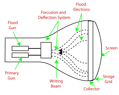
It is used to store the picture information as charge distribution behind the phosphorus coated screen.
It has two guns:
Primary gun: used to store the picture information
Flood or secondary gun: used to display a picture on the screen.
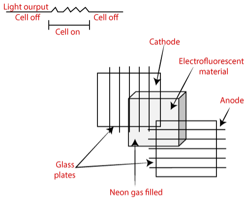
1.3.6 Plasma Display
It is also called as gas discharge display.
It is type of flat panel display which uses tiny plasma cells.
It has following components:
Anode: used to deliver a positive voltage.
Cathode: used to provide negative voltage to gas cell
Gas plates: works as capacitor. As soon as the voltage passes, the cell lights regularly.
Fluorescent cell: As soon as the voltage passes to the neon gas it emits light.
1.3.7 3D Display
It is also called as stereoscope display technology.
It has capability to bring depth perception to the viewer.
It is used in 3D gaming and 3D TVs.
Some examples of 3D display are such as holographic display, retina display, fog display, etc.
The main purpose of openGL is to render 2D and 3D objects into the frame buffer as a software interface for graphics hardware.
The objects are considered as sequence of vertices which determines the geometric objects or pixels which defines the images.
OpenGL performs several steps to convert data into pixels to form a final desired image in the frame buffer.
Following figure shows the architecture of OpenGL:
It supports several basic primitives’ types such as points, lines, quadrilaterals and general polygons.
All the primitives are specified by the vertices.
It supports two types of primitives as:
Geometric Primitives: this primitive applied in geometric pipeline
Raster Primitives: this primitive passes through separate pipeline to the frame buffer.
Following figure shows the openGL primitives:
GLUT is the openGL utility toolkit.
It is used in libraries of utilities for openGL programs.
This program primarily performs system level i/o with the host operating system.
This has some functions such as window definition, window control, monitoring of keyboard and mouse input.
GLUT includes cubes, spheres and Utah teapot in geometric primitives for routine drawing.
It supports for creating pop-up menus.
Interaction Using Mouse:
Interaction can be done using mouse, keyboard and input devices.
GLUT supports the interaction with the computer mouse that is triggered when one of the three typical buttons are pressed.
When mouse button is pressed the mouse callback function is initiated.
The specification of the callback function is used when a specified button is given state at a certain location at that time command glutMouseFunc() is used.
The mouse buttons are specified as GL_LEFT_BUTTON, GL_RIGHT_BUTTON and GL_MIDDLE_BUTTON.
The state of the mouse buttons are specified with GLUT_DOWN used when button is pressed and GLUT_UP is used when it is released.
At last the callback parameters x and y indicates the location of mouse at the time of event.
Interaction Using Keyboard:
This interaction works same as mouse interaction.
The glutKeyboardFunc() is used as keyboard callback function.
The ASCII code becomes the parameter of the keyboard when key is pressed.
The x and y coordinates of the mouse curor at the time of event.
The special keys of keyboard are works as triggers.
Following are the callback functions of some of the keys on the keyboard:
GLUT_KEY_UP | Up arrow |
GLUT_KEY_RIGHT
| Right arrow |
GLUT_KEY_DOWN
| Down arrow |
GLUT_KEY_PAGE_UP
| Page up |
GLUT_KEY_PAGE_DOWN
| Page down |
GLUT_KEY_HOME
| Home |
GLUT_KEY_END
| End |
GLUT_KEY_INSERT
| Insert |
It is a function that is executed when a particular event is recognized by the program.
When the event is comes inside the queue then recognition happens then program has expressed an interest in event.
The key when it uses an event in program then the program expressed an interest in event to indicate what function is to be executed when event happens.
Thus process is known as registering a callback for an event.
The registering of event is called when an event is registered for a callback function.
Following are some examples of events:
The selection process is used to select specific objects for some manipulation.
For selection process we use picking technique.
The special picking matrix in conjunction with the projection matrix to restrict drawing to small region of the viewport, near the cursor.
After this some part of input is allow as clicking the mouse button to initiate the selection process.
When selection mode is initiated and the special picking matrix is used then objects are drawn near the cursor causes the selection hits.
Hence during the picking typically determining which objects are drawn near the cursor.
For all this process before calling the standard projection matrix, need to use utility routine i.e. gluPickMatix() to multiply specified projection matrix by special picking matrix.
The center of picking region is passed with coordinates x and y at the cursor location.
The width and height is used to define the picking region in screen coordinates.
The current viewport can also be specified by using glGetIntegerv (GL_VIEWPORT, viewport).
The process of representing continuous graphics object as a collection of discrete pixels is called scan conversion.
For example, line is defined by two end points, the circle is defined by radius.
1.13.1 Digital Differential Analyzer (DDA)
Digital differential analyzer (DDA) is the simple line generation algorithm.
Line connects two points.
Hence to draw any line we need at least two points.
Hence we prefer one point as (X1,Y1) and second point is (X2,Y2).
Following are some steps to perform DDA algorithm.
Step 1: Get the input (X1,Y1) and (X2,Y2)
Step 2: calculate the slope of the line using inputs.
M= Y2-Y1/X2-X1
Step 3: according to slope of the line we need to decide the case which gives the next point of line.
Following are three cases are used to solve the DDA algorithm.
Case 1: m<1 Xn=X1+1 and Yn=Y1+m
Case 2: m>1 Xn=X1+1/m and Yn=Y1+1
Case 3: m=1 Xn=X1+1 and Yn=Y1+1
Step 4: the process continues till we get the input point(X2, Y2). Then the line generates with the help of coordinates that we occur.
Example:
Inputs: (X1,Y1)=(0,0) and (X2,Y2)=(8,4)
M= Y2-Y1/X2-X1
M=4-0/8-0
M = 0.5
Here M=0.5
Hence follow case 1 where M<1 then Xn=X1+1 and Yn=Y1+m
X1 | Y1 | Xn | Yn |
0 | 0 | 0 | 0 |
0+1=1 | 0+0.5=0.5 | 1 | 1 |
1+1=2 | 0.5+0.5=1 | 2 | 1 |
2+1=3 | 1+0.5=1.5 | 3 | 2 |
3+1=4 | 1.5+0.5=2 | 4 | 2 |
4+1=5 | 2+0.5=2.5 | 5 | 3 |
5+1=6 | 2.5+0.5=3 | 6 | 3 |
6+1=7 | 3+0.5=3.5 | 7 | 4 |
7+1=8 | 3.5+0.5=4 | 8 | 4 |
At last we get the last point (X2,Y2)=(8,4) we stop.
1.13.2 Bresenham’s Line Drawing Algorithm
It is another line generation algorithm known as incremental scan conversion algorithm.
It uses only integer calculations.
Following are steps to perform bresenham’s algorithm.
Step 1: Get the input (X1,Y1) and (X2,Y2)
Step 2:find decision parameter Pk and P0
Pk=2∆Y - ∆X
Where ∆X=X2-X1 and ∆Y=Y2-Y1
Step 3: according to the value of Pk we need to decide the case which gives the next point of line.
Following are three cases are used to solve the bresenham’s algorithm.
Case 1: Pk>0, Pk+1=Pk + 2 ∆Y - 2 ∆X
Where Xn=X1+1 and Yn=Y1+1
Case 2: Pk<0, Pk+1=Pk + 2 ∆Y
Where Xn=X1+1 and Yn=Y1+1
Step 4: the process continues till we get the input point(X2, Y2). Then the line generates with the help of coordinates that we occur.
Example:
Step 1: Get the input (X1,Y1) and (X2,Y2)
(X1,Y1)=(20,10) and (X2,Y2)=(30,18)
Step 2: find decision parameter Pk and P0
Pk=2 ∆Y - ∆X
Where ∆X=X2-X1=30-20=10 and∆Y=Y2-Y1=18-10=8
Hence, Pk=2 ∆Y - ∆X = 2*8-10= 16-10=6
Pk | Xn | Yn |
>0 | 21 | 11 |
2>0 | 22 | 12 |
-2<0 | 23 | 12 |
14>0 | 24 | 13 |
10>0 | 25 | 14 |
6>0 | 26 | 15 |
2>0 | 27 | 16 |
-2<0 | 28 | 16 |
14>0 | 29 | 17 |
10>0 | 30 | 18 |
At last we get the last point (X2, Y2)= (30,18) we stop.
It is difficult to draw circle than line drawing.
The equation of circle is r2=X2+Y2
There are some circle drawing algorithm as follows:
1.14.1 Digital Differential Analyzer (DDA) Circle Drawing Algorithm
This algorithm uses the incremental method to draw each point.
The algorithm calculates the starting point and by the value of E the value of x and ycoordinates will be increases and decreases respt.
The equation of circle is r2=X2+Y2
To calculate the value of E,
We have formula,
2n-1<=r <=2n where r = radius of circle
E=2^-n=1/2^n
E is used to calculate the value of circle point which helps to draw a circle as
X2=X1+E Y1 for x and
Y2=Y1- E X2 for y
Algorithm:
Step 1: Read the radius r of the circle and calculate value of E
Step 2: Start X=0 i.e. initial point and
Start Y=r i.e. radius
Step 3: X1=0 and Y1=r
Step 4:
Do {
X2=X1+E Y1
Y2=Y1-E X2
//Here X2 represents Xn+1 and X1 represent Xn
//Xn is from equation of circle
Plot(int X2,int Y2)
//here swapping points to calculate next closest pixel
X1=X2
Y1=Y2
}
While ((Y1-Y0)< E or (X0-X1)>E)
//here while condition is to check the current position is starting point or not, if current point is not starting point then repeats.
Step 5: stop
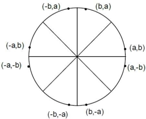
1.14.2 Bresenham’s Circle Drawing Algorithm
Following circle shows the 8 portions from which we will occur the coordinates of circle.
Algorithm:
Step 1: input of circle radius r, (Xc,Yc)
Step 2: initial value X=0 and Y=r
Step 3: plot pixel (X+Xc,Y+Yc)
Step 4: decision parameter Pk=3-2r
Step 5: start of loop
If Case 1:
If Pk<0 then Pk+1=Pk+4X+6
Where Xn=X+1 and Yn=Y
Else Case 2:
If Pk>0 then Pk+1=Pk+4(X-Y)+10
Xn=X+1 and Yn=Y-1
Step 6: X=Y stop
Example:
Given R=10
Hence Y=R
If we want to draw circle in center then we have given the center points as (Xc,Yc)=(2,2)
Decision parameters are Pk and P0.
P0=3-2r
Here, P0=3-2*10=3-20=-17
Hence Pk=P0= -17
Following are two cases that will be decided according to Pk’s value.
Case 1:
If Pk<0 then Pk+1=Pk+4X+6
Where Xn=X+1 and Yn=Y
Case 2:
If Pk>0 then Pk+1=Pk+4(X-Y)+10
Xn=X+1 and Yn=Y-1
Pk | Xn | Yn |
-17<0 | 0 | 10 |
-17+4*1+6=-7<0 | 1 | 10 |
-7+4*2+6=7>0 | 2 | 10 |
7+4*(3-9)+10=-7<0 | 3 | 9 |
-7+4*4+6=15>0 | 4 | 9 |
15+4*5-4*8+10=-7<0 | 5 | 8 |
-7+4*6+6=23>0 | 6 | 8 |
| 7 | 7 |
Here X=Y then stop
1.14.3 Mid-Point Circle Drawing Algorithm
Algorithm:
Step 1: input of circle radius r, (Xc,Yc)
Step 2: initial value X=0 and Y=r
Step 3: plot pixel (X+Xc,Y+Yc)
Step 4: decision parameter Pk=1-r
Step 5: start of loop
If Case 1:
If Pk<0 then Pk+1=Pk+2X+1
Where Xn=X+1 and Yn=Y
Else Case 2:
If Pk>0 then Pk+1=Pk+2X+1-2Y
Xn=X+1 and Yn=Y-1
Step 6: X=Y stop
Example:
Given R=10
Hence Y=R
If we want to draw circle in center then we have given the center points as (Xc,Yc)=(2,2)
Decision parameters are Pk and P0.
P0=1-r
Here, P0=1-10=-9
Hence Pk=P0= -9
Following are two cases that will be decided according to Pk’s value.
Case 1:
If Pk<0 then Pk+1=Pk+2X+1
Where Xn=X+1 and Yn=Y
Case 2:
If Pk>0 then Pk+1=Pk+2X+1-2Y
Xn=X+1 and Yn=Y-1
Pk | Xn | Yn |
-9<0 | 0 | 0 |
-9+2*1+1=-6<0 | 1 | 10 |
-6+2*2+1=-1<0 | 2 | 10 |
-1+2*3+1=6>0 | 3 | 10 |
6+2*4+1-2*9=-3<0 | 4 | 9 |
-3+2*5+1=8>0 | 5 | 9 |
8+2*6+1-2*8=5>0 | 6 | 8 |
| 7 | 7 |
Now X=Y hence we stop the loop.
If we wants to draw the circle at center then we need coordinates as (Xc,Yc) Then coordinates becomes X=Xn+Xca and Y=Yn+Yc.