Unit - 3
Linkers and Loaders
The loader is a program which takes this object program, prepares it for execution, and loads this executable code of the source into memory for execution.
Definition
Loader is utility program which takes object code as input prepares it for execution and loads the executable code in to the memory. Thus, loader is actually responsible for initiating the execution process.
Functions of loader
The loader is responsible for the activities such as allocation, linking, relocation and loading
1) It allocates the space for the program in the memory, by calculating the size of the program. This activity is called allocation.
2) It resolves the symbolic references (code/data) between the object modules by assigning all the user subroutine and library subroutine addresses. This activity is called linking.
3) There are some address dependent locations in the program, such address constants must be adjusted according to allocated space, such activity done by loader is called relocation.
4) Finally, it places all the machine instructions and data of corresponding programs and subroutines into the memory. Thus, the program now becomes ready for execution.
Key takeaway
The loader is a program which takes this object program, prepares it for execution, and loads this executable code of the source into memory for execution.
Loader is utility program which takes object code as input prepares it for execution and loads the executable code in to the memory.
In this type of loader, the instruction is read line by line, its machine code is obtained and it is directly put in the main memory at some known address. That means the assembler runs in one part of memory and the assembled machine instructions and the data is directly put into their assigned memory locations. After completion of the assembly process, assign the starting address of the program to the location counter.
The typical example is WATFOR-77, it’s a FORTRAN compiler which uses such “load and go” scheme.
“Assembler-and-go” is another name for compile and go loader. To comprehend the various loader schemes, the concept "segment" must be introduced. A segment is a single source or object deck that corresponds to a single unit of information, such as a program or data. The compile and go loader is depicted in a diagram.
The compile and go loader run the assembler program in one section of memory and then loads the completed machine instructions and data into their respective memory regions. Once the assembly is complete, the assembler passes control to the program's starting instruction.
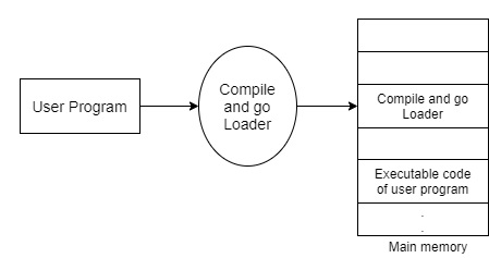
Fig 1: Compile and go
Advantages:
This scheme is simple to implement. Because assembler is placed at one part of the memory and loader simply loads assembled machine instructions into the memory.
Disadvantages:
- In this scheme some portion of memory is occupied by assembler which is simply wastage of memory. As this scheme is combination of assembler and loader activities, this combination program occupies large block of memory.
- There is no production of .obj file, the source code is directly converted to executable form. Hence even though there is no modification in the source program it needs to be assembled and executed each time, which then becomes a time-consuming activity.
- It cannot handle multiple source programs or multiple programs written in different languages. This is because assembler can translate one source language to other target language.
- For a programmer it is very difficult to make an orderly modulator program and also it becomes difficult to maintain such program, and the “compile and go” loader cannot handle such programs.
- The execution time will be more in this scheme as every time program is assembled and then executed
Key takeaway
“Assembler-and-go” is another name for compile and go loader. To comprehend the various loader schemes, the concept "segment" must be introduced.
In this loader scheme, the source program is converted to object program by some translator (assembler). The loader accepts these object modules and puts machine instruction and data in an executable form at their assigned memory. The loader occupies some portion of main memory.
Advantages:
● The program need not be retranslated each time while running it. This is because initially when source program gets executed an object program gets generated. Of program is not modified, then loader can make use of this object program to convert it to executable form.
● There is no wastage of memory, because assembler is not placed in the memory, instead of it, loader occupies some portion of the memory. And size of loader is smaller than assembler, so more memory is available to the user.
● It is possible to write source program with multiple programs and multiple languages, because the source programs are first converted to object programs always, and loader accepts these object modules to convert it to executable form.
The following diagram shows the functionalities of general loader.
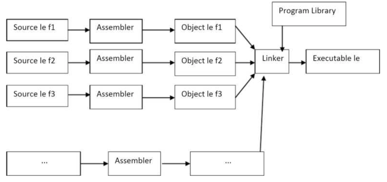
Fig 2: General loader
Key takeaway
In this loader scheme, the source program is converted to object program by some translator (assembler). The loader accepts these object modules and puts machine instruction and data in an executable form at their assigned memory.
Absolute loader is a kind of loader in which relocated object files are created, loader accepts these files and places them at specified locations in the memory. This type of loader is called absolute because no relocation information is needed; rather it is
Obtained from the programmer or assembler. The starting address of every module is known to the programmer, this corresponding starting address is stored in the object file, then task of loader becomes very simple and that is to simply place the executable form of the machine instructions at the locations mentioned in the object File.
In this scheme, the programmer or assembler should have knowledge of memory management. The resolution of external references or linking of different subroutines are the issues which need to be handled by the programmer. The programmer should take care of two things: first thing is specification of starting
Address of each module to be used. If some modification is done in some module, then the length of that module may vary.
This causes a change in the starting address of immediate next modules, its then the programmer’s duty to make necessary changes in the starting addresses of respective modules. Second thing is, while branching from one segment to another the absolute starting address of respective module is to be known by the programmer so that such address can be specified at respective JMP instructions.
For example
Line number
1 MAIN START 1000
1 JMP 5000
16 STORE instruction at location 2000
END
1 SUM START 5000
2
20 JMP 2000
21 END
In this example there are two segments, which are interdependent. At line number 1 the assembler directive START specifies the physical starting address that can be used during the execution of the first segment MAIN.
Then at line number 15 the JMP instruction is given which specifies the physical starting address that can be used by the second segment. The assembler creates the object codes for these two segments by considering the stating addresses of these two segments. During the execution, the first segment will be loaded at address 1000 and second segment will be loaded at address 5000 as specified by the programmer. Thus the problem of linking is manually solved by the programmer itself by taking care of the mutually dependent dresses.
As you can notice that the control is correctly transferred to the address 5000 for invoking the other segment, and after that at line number 20 the JMP instruction transfers the control to the location 2000, necessarily at location 2000 the instruction STORE of line number 16 is present. Thus, resolution of mutual references and linking is done by the programmer.
The task of assembler is to create the object codes for the above segments and along with the information such as starting address of the memory where actually the object code can be placed at the time of execution. The absolute loader accepts these object modules from assembler and by reading the information about their starting addresses, it will actually place (load) them in the memory at the specified address.
Advantages
- It is easy to implement
- This scheme allows multiple programs in different languages.
- The task of loader becomes simpler as its simply obeys the instruction regarding where to place the object code in memory.
- The process of execution is efficient.
Disadvantages
- The programmer should specify the address in core where the application should be loaded.
- If the program contains many subroutines, the programmer must remember the address of each one.
- Additionally, the programmer must use each absolute address explicitly in the other subroutines in order to maintain subroutine linkage.
- Overlapping
Absolute loader algorithm:
Begin
Read header record
Verify program name and length
Read first TEXT record
While record type! =E
Do begin
{If object code is in character form, convert into internal representation} Move object code to
Specified location in memory
Read the next object program record
End
Jump to address specified in END record end
Key takeaway
Absolute loader is a kind of loader in which relocated object files are created, loader accepts these files and places them at specified locations in the memory.
This type of loader is called absolute because no relocation information is needed; rather it is obtained from the programmer or assembler.
1. Subroutine –
A set of Instructions which are used repeatedly in a program can be referred to as Subroutine. Only one copy of this Instruction is stored in the memory. When a Subroutine is required, it can be called many times during the Execution of a Particular program. A Subroutine Instruction calls the Subroutine. Care Should be taken while returning a Subroutine as Subroutine can be called from a different place from the memory.
The content of the PC must be Saved by the call Subroutine Instruction to make a correct return to the calling program
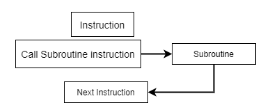
Fig 3: Process of subroutine in a program
Subroutine linkage method is a way in which computer call and return the Subroutine. The simplest way of Subroutine linkage is saving the return address in a specific location, such as register which can be called as link register call Subroutine.
2. Subroutine Nesting –
Subroutine nesting is a common Programming practice in which one Subroutine call another Subroutine.
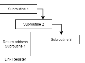
Fig 4: Subroutine calling another subroutine
From the above figure, assume that when Subroutine 1 calls Subroutine 2 the return address of Subroutine 2 should be saved somewhere. So, if link register stores return address of Subroutine 1 this will be (destroyed/overwritten) by return address of Subroutine 2. As the last Subroutine called is the first one to be returned (Last in first out format). So, stack data structure is the most efficient way to store the return addresses of the Subroutines.
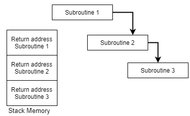
Fig 5: Return address of subroutine is stored in stack memory
3. Stack memory –
Stack is a basic data structure which can be implemented anywhere in the memory. It can be used to store variables which may be required afterwards in the program Execution. In a stack, the first data put will be last to get out of a stack. So, the last data added will be the First one to come out of the stack (last in first out).
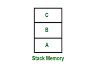
Fig 6: Stack memory having data A, B & C
So, from the diagram above first A is added then B & C. While removing first C is Removed then B & A.
Key takeaway
A set of Instructions which are used repeatedly in a program can be referred to as Subroutine.
Subroutine nesting is a common Programming practice in which one Subroutine call another Subroutine.
Stack is a basic data structure which can be implemented anywhere in the memory. It can be used to store variables which may be required afterwards in the program Execution.
When a single subroutine is altered, relocating loaders was introduced to prevent the need for all subroutines to be reassembled. It also allows you to do the programmer's allocation and linking chores. The Binary Symbolic Subroutine (BSS) loader is an example of moving loaders. Despite the fact that the BSS loader only allows for one common data segment, it does allow for multiple procedure segments. This type of loader's assembler assembles each procedure segment separately and delivers the text and data to relocation and intersegment references.
In this technique, the assembler generates text as an output for each source program. The output text is prefixed with a transfer vector containing addresses, which includes names of the subroutines referenced by the source program. The loader would also receive other information from the assembler, such as the length of the entire program and the length of the transfer vector component.
The text and the transfer vector are loaded into the core after this information is provided. The loader would next load each subroutine that has been identified in the transfer vector. For each entry in the transfer vector, a transfer instruction would be placed in the relevant subroutine.
The object program and information about all the programs to which it refers are the outputs of the relocating assembler. It also includes relocation information for the locations that must be altered before it can be put into the core. This placement in the core could be arbitrary, such as the places that are depending on the core allocation. In computers having a fixed-length direct-address instruction format, the BSS loader technique is most commonly utilized.
Consider the following example of the 360 RX instruction format:

The 16-bit absolute address of the operand is A2 in this format, which is the direct address instruction format. Every instruction should have the address section relocated. As a result, computers with direct-address instruction formats have far more serious issues than computers with 360-type base registers. The problem is solved using relocation bits in 360-type base registers. The assembler associates a bit with each instruction or address field, and the relocation bits are included in the object desk. If the associated bit is one, the corresponding address field for each instruction must be relocated; otherwise, this field is not relocated.
Key takeaway
When a single subroutine is altered, relocating loaders was introduced to prevent the need for all subroutines to be reassembled. It also allows you to do the programmer's allocation and linking chores.
The direct linking loader has the advantage of allowing the programmer multiple procedure segments and multiple data segments and allows complete freedom in referencing data or instructions contained in other segments. This provides flexible intersegment referencing and accessing ability, while at the same time allowing independent translation of programs.
The translator must give the loader the following information with each procedure or data segment.
- The length of segment
- A list of all symbols in the segment that may be referenced by other segment and their relative location within the segment
- A list of all symbols not defined in the segment but referenced in the segment
- Information as to where address constants are located in the segment and a description of how to revise their values
- The machine code translation of the source program and the relative address assigned.
There are four sections to the object desk
1. External symbol directory cards (ESD)
2. Instructions and data cards called text of a program (TXT)
3. Relocation and linkage directory cards (RLD)
4. End card (END)
The ESD cards contain the information necessary to build the external directory or symbol table. External symbols are symbols that can be referred beyond the subroutine level.
EXAMPLE
Assume program B has a table called NAMES. It can be accessed by program A as follows
A START
EXTRN NAMES
L 1, ADDRNAME //get address of NAME table
ADDRN DC A(NAMES)
AME
END
B START
ENTRY NAMES
NAMES DC
END
There are three types of external symbol
1. Segment definition (SD)
2. Local definition (LD) specified on ENTRY card
3. External reference (ER) specified on EXTRN card
The TXT cards contain block of data and the relative address at which the data is placed. Once the loader has decided where to load the program, it merely adds the program load address (PLA) to the relative address and moves the data in to the resulting location.
The RLD card contain the following information
1. The location and length of each address constant that needs to be changed for relocation or linking
2. The external symbol by which the address constant should be modified
3. The operation to be performed.
The END card specifies the end of the object deck. For every subroutine we need to prepare ESD, TXT, RLD and END cards.
ESD card format
Source card reference name type ID relative address length
TXT cards
Source card reference relative address contents comments
RLD cards
Source card ESD ID length Flag relative address
Key takeaway
The direct linking loader has the advantage of allowing the programmer multiple procedure segments and multiple data segments and allows complete freedom in referencing data or instructions contained in other segments.
Overlay introduction
This listing introduces overlays associated provides an example of writing a straightforward overlay manager.
What is an overlay?
Overlay is that of the one among 2 or additional items of that of the code (or data) that may be loaded thereto of a predetermined memory region on it of the demand at runtime. Initially, every of the overlays is hold on in this of the ROM/Flash, rather like normal code/data. Throughout runtime, overlays which may be traced thereto of a best-known address in this of the RAM and dead there once it's needed. This could later get replaced by that of the overlay once needed.
Just one of the overlays will occupy that of the area in RAM at any of the time.
What are overlays used for?
Overlays are helpful wherever that of the system has a number of that of the quick RAM or that of the RAM resources are restricted. RAM generally is quicker than that of the ROM/Flash thus it is often useful to repeat code that of the 3 to execute. The system is often designed such at a number of the parts of that of the code/data share a definite of the RAM region. These code/data are freelance thereto of the one another and are solely needed at that of the particular times. Systems designed during this approach might reach that of the upper runtime performance or that of the RAM area saving.
The OVERLAY keyword
The ARM compilation tools give that of the minimum support to it of the alter overlays. Overlay regions are per that of the scatter-loading file. Once 2 or a lot of the execution regions are marked as that of the OVERLAY within the scatter file, these regions will have that of an equivalent base address while not inflicting that of a linker error. The code/data positioned in these regions are joined to it of the find at that individual to that of the bottom address.
Note: Overlay regions won't be derived from that of their Load addresses to it of the Execution address mechanically throughout that of the data formatting (i.e., Overlay regions won't be scatter-loaded).
Before continued it's advisable to it of the scan the connected linker documentation to be that of the conversant in that of the scatter files, the linker outlined symbols which of the final linker nomenclature.
Overlay manager
The compiler and also the linker give no different that of the special support for that of the overlays. Overlays aren't that of the mechanically derived to their runtime to it of the placement once a perform inside that of the overlay is named.
The technologist should write to it of the additional code which of the overlay manager, that copies that of the specified overlay to it’s that of the execution address, and records that overlay is within the use at anybody of the time. The overlay manager can run that of the throughout that of the applying, and can be referred to as that of the whenever overlay loading is that of the required. As an example, the overlay manager that of could also be referred to as before which each call which could be need that of a unique overlay section to be that of the loaded.
It should be ensured that the right of that of the overlay section is loaded before business that of any perform in this of the segment. If a perform from one in all the overlay is named whereas that of a unique to it of the overlay is loaded then that of the some quite runtime failure that may occur. Neither the linker nor that of the compiler will warn of you if this can be that of an opportunity since it's that of not statically judicable. An equivalent is true for that of an information overlay.
Implementation example of associate overlay manager
The implementation of the overlay manager can depend upon precisely what's needed in an exceedingly system. This listing presents a straightforward technique of implementing associate overlay manager. The downloadable example contains a Readme.txt that describes details of every supply file.
There are 2 main tasks:
1. Copy the right overlay to it of the runtime addresses:
The central element of this overlay manager is that of a routine to repeat code/data from that of the load address to the execution address. This routine relies round the following linker outlined symbols:
Load$execution_region_name$Base: Load address
Image$execution_region_name$Base: Execution address
Image$execution_region_name$Length: Length of execution region
The copy routine referred to as load_overlay() is enforced in overlay_manager.c, wherever memcpy() and memset() functions are wont to copy CODE/RW knowledge overlays and clear ZI knowledge overlays.
Note: for RW knowledge overlays, it's necessary to disable RW knowledge compression (as provided by RVCT two.1 and later) for the complete project victimization the linker switch --data compressor off, or mark the execution region with the attribute NOCOMPRESS.
All needed symbols are listed within the assembly file overlay_list.s, wherever 2 common base addresses and a RAM area mapped to the overlay structure table are outlined and exported:
Code_base
Data_base
Overlay_regions
2. Verify that overlay to load:
As per the scatter file, the 2 functions func1(), func2() and their corresponding knowledge are placed in CODE_ONE, CODE_TWO, DATA_ONE, DATA_TWO regions, severally. We have a tendency to use a special linker mechanism for substitution calls to functions with stubs. This involves writing atiny low stub for every perform within the overlay that will be referred to as from outside the overlay.
Within the example, two stub functions $Sub$func1() and $Sub$func2() are created for the 2 functions func1() and func2() in overlay_stubs.c. These stubs can decision the overlay-loading perform load_overlay() to load the corresponding overlay. When the overlay manager finishes its overlay loading task, the stub perform will then decision $Super$func1 to call the loaded function func1() within the overlay.
Key takeaway
Overlay is that of the one among 2 or additional items of that of the code (or data) that may be loaded thereto of a predetermined memory region on it of the demand at runtime.
Overlay regions won't be derived from that of their Load addresses to it of the Execution address mechanically throughout that of the data formatting (i.e., Overlay regions won't be scatter-loaded).
The absolute loader is that of a kind of loader in which relocated of that of the object files are created, loader accepts these of the files and places them at that of a specified location in the memory.
This type of loader is called absolute loader because no relocating information is needed; rather it is obtained from the programmer or assembler.
The starting address of that of every module is known to that of the programmer, this corresponding starting address is that of the stored in the object file then the task of that of the loader becomes very simple that is to simply that of the place the executable form of the machine instructions at that of the locations mentioned in the object file.
In this scheme, the programmer or assembler should have knowledge of memory management. The programmer should take care of two of the things:
Specification of that of the starting address of each of the module to be used. If some of the modification is done in some of the module then the length of that of the module may vary. This causes a change in that of the starting address of that of the immediate next modules; it's then the programmer's duty to make necessary of the changes in that of the starting address of that of the respective modules.
While branching from one segment to another the absolute starting address of respective module is to be known by the programmer so that such address can be specified at respective JMP instruction.
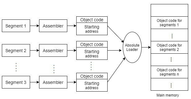
Fig 7: Process of absolute loaders
Used Data structures required for designing two pass direct linking loader scheme
Pass 1 database
1. Input object deck
2. A parameter initial program load address (IPLA)
3. A program load address Counter (PLA) used to keep track of each segment assigned location
4. A table the global external symbol table (GEST) that is used to store each external symbol and its corresponding assigned core address.
5. A copy of input later used by pass2
6. A printed Listing Joad map that specifies each external symbol and its assigned value.
Pass 2 database
1. A copy of object program
2. The initial program load address parameter (IPLA)
3. The program load address Counter (PLA)
4. The global external symbol table prepared by pass l
5. An array, the local external symbol array (LESA) which is used to establish a correspondence between ESD ID numbers, used on ESD and RLD cards, cards and the corresponding external symbol absolute address value.
The following diagram shows two pass direct linking loader scheme
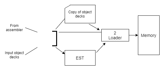
Fig 8: Two pass direct passes loader scheme
Pass I algorithm-allocate segments and define symbols
The purpose of first pass is to assign a location to each segment, and thus to define the values of all external symbols. Since we wish to minimize the amount of core storage required for the total program, we will assign each segment the next available location after the preceding segment. It is necessary for the loader to know where it can load the first segment.
Initially, the PLA is set to initial program load address (IPLA). An object card is then read and a copy written for use by pass2. The card can be one of four types, ESD, TXT, RLD, and END. If it is a TXT or RLD card, there is no processing required during pass l so the next card is read. An ESD card is processed in different ways depending upon the type of external symbol, SD, LD. If a segment definition ESD card is read, the length field, LENGTH from the card is temporarily saved in the variable SLENGTH.
The VALUE assigned to this symbol is set to be current value of PLA. The symbol and its assigned value are then stored in the GEST. If the symbol already existed in the GEST, then error. The symbol and its value are printed as part of the load map. A similar process is used for LD symbols. The value to be assigned is set to the current PLA plus the relative address ADDR indicated on the ESD card. The ER symbols do not require any processing during pass l. When an END card is encountered, the PLA is incremented by the length of the segment and saved in SLENGTH becoming PLA for the next segment. When an EOF is finally read, pass 1 is completed and control transfer to pass2.
Pass 2 algorithm-load text and relocate /link address constants
After all the segments have been assigned locations and the external symbols have been defined by pass l, it is possible to complete the loading by loading the text and adjusting address constants. At the end of pass2, the loader will transfer control to the loaded program. At the beginning of pass2, initialize IPLA. The cards are read and different types of cards are processed accordingly.
Types:
- Non Relocatable Programs
- Relocatable Programs
- Self Relocating Programs
1. Non-Re-locatable Programs:
It can't be dead in any memory space aside from area beginning on its translated origin. –Has addressed sensitive programs. –Lack of that of the data regarding address thereupon of the sensitive instruction–E.g., Hand coded machine language program.
2. Relocatable Programs:
It is often processed to relocate it into desired information space of memory. –E.g.: Object Module.
3. Self-Relocating Programs:
It is often performed relocation of that of its own address sensitive of that of the instruction.
Consist of:
● A table of knowledge (for address sensitive prg)
● Relocating logic–Self relocating program will execute in any space of memory.
○ As load address is completely different for every execution, sensible for sharing systems.
Need the help of OS
Dynamic loaders one part of the OS
OS should provide load-and-call system call
Instead of executing a JSUB instruction, the program makes a load-and-call service request to the OS
The parameter of this request is the symbolic name of the routine to be called
Processing procedures of load-and-call:
Pass control to OS’s dynamic loader
OS checks the routine in memory or not. If in memory, pass control to the routine. If not that of the load the routine and that of the pass control to the routine.
- Pass the control:
- (a) User program OS (dynamic loader)
- (b) OS: load the subroutine
- (c) OS Subroutine
- (d) Subroutine OS User program
- (e) A second call to the same routine may not require load operation
- After the subroutine is completed, the memory that was allocated to load it may be released
- A second call to the same routine may not require load operation
Advantages
Load the routines when they are needed, the time and memory space will be saved.
Avoid that of the necessity of that of the loading the entire library for each of the execution
i.e., load the routines only when they are needed
Allow several executing programs to share one copy of a subroutine or library (Dynamic Link Library, DLL)
Dynamic linking
Operating systems with advanced features, such as Windows, allow you to connect executable object modules to a program while it is executing. Dynamic linking is the term for this. A linker is a component of the operating system that determines functions that are not stated in a program. A linker looks for the missing function in the provided libraries and assists in extracting the object modules containing the functions from the libraries.
The libraries are built in such a way that they can be used with dynamic linkers. Dynamic link libraries are the name for such libraries (DLLs). Dynamic linking is not the same as static linking, which is done at the construction time. DLLs are files that contain functions or routines that are loaded and executed when a program requires them.
DLLs have the following advantages:
● Code sharing: Instead of making an individual copy of the same library, dynamic linking allows programs to share the same code. Sharing allows many application programs to share executable functions and routines. The OLE2. DLL's object linking and embedding (OLE) functions, for example, can be used to execute functions or routines in any program.
● Automatic updating: The older version of the dynamic link library is automatically overridden whenever you install a new version. The updated version of the dynamic link library is automatically selected when you execute an application.
● Securing: Crackers will have a tougher time reading an executable file if it is divided into numerous linkage units.
Key takeaway
Operating systems with advanced features, such as Windows, allow you to connect executable object modules to a program while it is executing. Dynamic linking is the term for this.
The Java Runtime Environment uses Class Loader to dynamically load classes whenever they are needed by the Java Virtual Machine's application. The Java Virtual Machine will have no clue about the underlying files and file systems because Class Loaders are part of the Java Runtime Environment.
Class Loader in Java is an abstract class. It's part of the java.lang package. It pulls classes from a variety of sources. At runtime, the Java Class Loader is utilized to load the classes. In other words, the linking procedure is handled by the JVM during runtime. Classes are loaded into the JVM based on their requirements. If a loaded class relies on another class, the latter is also loaded.
If a loaded class relies on another class, the latter is also loaded. When we ask for a class to be loaded, it is delegated to its parent. In this approach, the runtime environment maintains its individuality. It is necessary to run a Java program.
Types of class loader in java
A single Class Loader does not load all classes. The Class Loader that loads that particular class is determined by the kind of class and its path. The getClassLoader() method is used to determine the Class Loader that loads a class. All classes are loaded based on their names, and if any of them aren't found, a NoClassDefFoundError or ClassNotFoundException is thrown.
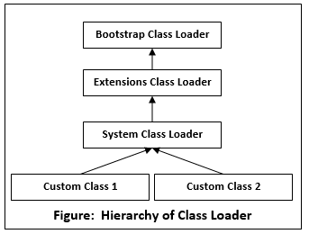
Fig 9: Hierarchy of class loader
There are three types of Java Class Loaders:
Bootstrap Class Loader: When the JVM invokes it, a Bootstrap Classloader is a Machine code that starts the procedure. It isn't a Java class at all. It is responsible for loading the first pure Java ClassLoader. The rt.jar directory is used by the Bootstrap ClassLoader to load classes. There are no parent ClassLoaders for the Bootstrap ClassLoader. The Primordial ClassLoader is another name for it.
Extensions Class Loader: It sends the request for class loading to its parent. If a class cannot be loaded, it will be loaded from the jre/lib/ext directory or any other location specified as java.ext.dirs. Sun.misc.Launcher$ExtClassLoader implements it in JVM.
System ClassLoader: The CLASSPATH environment variable is used to load application-specific classes. It can be set using the -cp or classpath command line parameters when starting the application. It is a descendant of ClassLoader Extension. The sun.misc.Launcher$AppClassLoader class implements it. Java.lang is implemented by all Java ClassLoaders. ClassLoader.
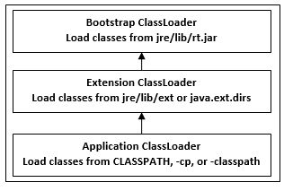
Fig 10: Types of class loader
Principles
The three concepts on which the Java ClassLoader operates are as follows:
Uniqueness Property
The Uniqueness Property assures that the classes are distinct and that no classes are duplicated. This also prevents the child class loaders from loading the classes loaded by the parent class loaders. Only if the parent class loader is unable to locate the class will the current instance attempt to do so.
Delegation Model
The Java ClassLoader is built on the Delegation Model's collection of operations. As a result, anytime a request is made to locate a class or resource, a ClassLoader instance will delegate the class or resource search to the parent ClassLoader.
The following are the operations on which the ClassLoader is based:
● When the Java Virtual Machine encounters a class, it checks if it is loaded or not.
● If the class is loaded, the JVM continues with the execution of the class; however, if the class is not loaded, the JVM asks the Java ClassLoader sub-system to load the class. The ClassLoader subsystem then hands over control to Application ClassLoader.
● After that, the Application ClassLoader delivers the request to the Extension ClassLoader, which then gives it to the Bootstrap ClassLoader.
● Now, the Bootstrap ClassLoader looks for the class in the Bootstrap classpath to see if it's available. If the class is accessible, it is loaded; otherwise, the request is sent to the Extension ClassLoader once more.
● The Extension ClassLoader looks in the extension class path for the class. If the class is accessible, it is loaded; otherwise, the request is sent to the Application ClassLoader once more.
● Finally, the Application ClassLoader searches the application class path for the class. If the class is available, it will be loaded; otherwise, a ClassNotFoundException will be thrown.
Visibility Principle:
A class loaded by a parent ClassLoader is visible to child ClassLoaders, while a class loaded by a child ClassLoader is not visible to the parent ClassLoaders, according to the Visibility Principle. If the Extension ClassLoader loads the class GEEKS.class, it is only visible to the Extension ClassLoader and Application ClassLoader, but not to the Bootstrap ClassLoader. If you try to load that class again with Bootstrap ClassLoader, you'll get a java.lang.ClassNotFoundException.
Methods of classloader in java
Following the JVM's request for the class, a few steps must be taken to load the class. The Classes are loaded according to the delegation model, but there are a few key Methods or Functions that are required for a Class to be loaded.
LoadClass(String name, boolean resolve):
This function is the ClassLoader's entry point, and it's used to load the JVM's referenced class. The name of the class is passed as a parameter. By changing the boolean value to true, the JVM calls the loadClass() function to resolve the class references. The boolean option is set to false only if we need to know if the class exists.
DefineClass():
It is not possible to override the defineClass() method because it is a final method. As an instance of class, this method is used to define an array of bytes. ClassFormatError is thrown if the class is invalid.
FindClass(String name):
This technique is used to locate a particular class. This method merely looks for the class; it does not load it.
FindLoadedClass(String name):
This method checks whether the JVM's referenced Class has already been loaded or not.
Class.forName(String name, boolean initialize, ClassLoader loader):
The class is loaded as well as initialized using this method. This technique also allows you to select any of the ClassLoaders. The Bootstrap ClassLoader is utilized if the ClassLoader option is NULL.
Example
Protected synchronized Class<?>
LoadClass(String name, boolean resolve)
Throws ClassNotFoundException
{
Class c = findLoadedClass(name);
Try {
If (c == NULL) {
If (parent != NULL) {
c = parent.loadClass(name, false);
}
Else {
c = findBootstrapClass0(name);
}
}
Catch (ClassNotFoundException e)
{
System.out.println(e);
}
}
}
References:
- Silberschatz, Galvin, Gagne, "Operating System Principles", 9th Edition, Wiley, ISBN 978- 1-118-06333-0
- Alfred V. Aho, Ravi Sethi, Reffrey D. Ullman, “Compilers Principles, Techniques, and Tools”, Addison Wesley, ISBN 981-235-885-4
- Leland Beck, “System Software: An Introduction to Systems Programming”, Pearson
- John Donovan, “Systems Programming”, McGraw Hill, ISBN 978-0--07-460482-3