Unit 3
Equilibrium
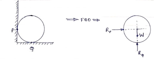
Free body diagram: -
If a body is shown with all external forces acting on it so that the body is in equilibrium, such diagram is called as free body diagram.
To draw the free body diagram, we have to remove all the restrictions like wall, floor, hinge, any other support and replace them by reactions which these support extents on the body.
Ex – 1) Draw FBD of a bar supported and loaded as shown below.

2) Draw FBD of sphere supported as shown below.
- Equilibrium
- A body is said to be in equilibrium if the resultant of all forces acting on it is zero.
- When the resultant of all the forces acting on the particle is zero, then, the particle is in equilibrium.
- If the resultant force acting on a particle is zero (or if particle is in equilibrium state) the, particle will remain at rest condition if it is originally at rest; or particle will move with constant speed in a straight line if it is originally in motion.
Condition for Equilibrium: R = 0 {  }
}
∑M = 0
Lami’s Theorem: - (Body is subjected to three forces)
If three coplanar concurrent forces are in equilibrium then, the ratio of magnitude of any force to the sine of angle between the other two is constant.
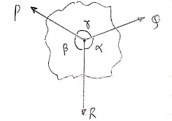
According to Lami’s Theorem:
Lami’s theorem can also be written as:If three coplanar concurrent forces acting at a point are in equilibrium, each force is proportional to the sine of angle between other two.
- Equilibrium of body subjected to two forces:

P=Q, body is in equilibrium P=Q, but body is not in equilibrium
If an object is subjected to forces acting at two points, then body will be in
Equilibrium only when those two forces are equal & opposite.
- Types of Support
- Roller Support: -
Roller support is show in two ways as shown:

- A free body diagram of roller support is shown in figure given below

- Roller support offers only one reaction; which is always perpendicular to the base or plane of roller.
- All the steel trusses of the bridges have one of their ends supported on roller.
- Main advantages of the support are that beam can easily move towards left or right due to expansion & contraction.
2. Hinge support

- In this case, end of the beam is hinged to the support as shown in figure above.
- This type of support offers two reactions, one is parallel to base and perpendicular to the base
- All the steel trusses of the bridges have one of their end roller supported & other end is hinged
- Main advantage of this support is that beam remains stable.
- If both ends of the beam are roller supported, then beam can not be stable. Thus, one support of beam is made roller supported and other is hinged.
3. Internal Hinge: -
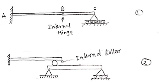
When two members are connected by the hinge then this type of support is called as internal Hinge.

4. Fixed support: -
Fixed support offers three reactions as shown in figure below.
- Reaction in horizontal direction.
- Reaction in vertical direction.
- Moment (fixing moment)

Fixed Support
Numerical on Lami’s Theorem.
(Equilibrium of three concurrent forces)
Que. 1 Find the axial force in the bar AB & AC as shown in figure.
 Consider the free body diagram of all forces at B.
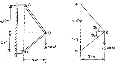
Q1 = tan -1  = 51.34º
Q2 = tan-1  = 45º
= 45º
Let the forces developed in the member AB & AC are FAB &FBC respectively. The force diagram will be as follows at B.
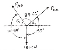
Applying Lami’s Theorem:


 FAB = 1067.19 N

FBC = 942.81 N
Que 2. Find the tensions in the string AB, BC, CD, DE of the given system as shown in figure. String BC is horizontal & pulley D is frictionless.
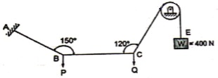
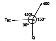
 The string passes over the pulley & is attached to weight w = 400 N.
Thus TCD = TDE = 400 N
Consider joint C & apply Lami’s theorem


Now consider FBD at joint B
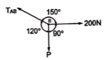
By using Lami’s theorem


TAB = 230.94 N

Que 3. Two identical spheres having weight 1000 N are kept in a container as shown in figure. Find the reaction at all contact surfaces.
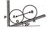
 Consider the free body diagram of sphere B as shown below:
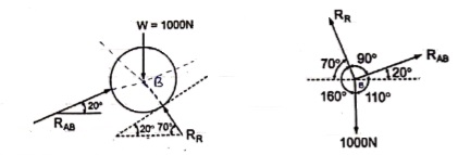
By lami’s theorem


 RRR = 939.69 N

 = RAB
= RAB
Now consider FBD of sphere A
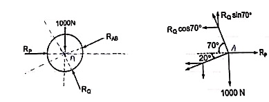
∑Fx = 0
-RB cos 20 – RQ cos 70 + Rp = 0
-342.02 cos 20 – RQ sin 70 + Rp = 0
 Rp = 321.39 + 0.34 RQ ------------------(1)
∑ fy = 0
RQ sin 70 – 342.02 sin 20 – 1000 = 0
 RQ = 1188.66 N - put in equation (1)
 Rp = 725.5 N
Que 4. Two members AB & BC are supporting a load of 200 kN as shown in figure. Find the forces developed in the members AB & BC
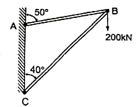
 Consider the free body diagram of joint B as shown in figure
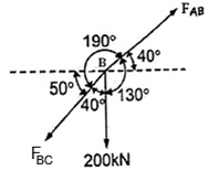
Assume that member BC is in compression & AB is in tension. By using Lami’s theorem at B,


 FAB = -740.33 kN
-ve sign indicates that member AB is not in Tension but is in compression.
Now,


-ve sign indicates that member BC is not in compression but in tension.
Que 5. A Sphere of weight 200 N rests on a smooth inclined plane. A sphere is kept in equilibrium by means of cable as shown. Find tension in cable and reaction.
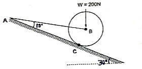
 Consider the FBD of sphere B as shown in figure above.
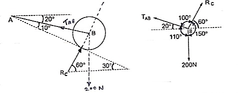
Applying lami’s theorem, we have


 RC = 190.84 N


 TAB = 101.54 N
Que 6. The bar AB supports a load of 500 kN as shown in figure. The bae is kept in equilibrium by means of horizontal rope. Find tension in rope and reaction at A,
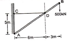
 Consider the FBD as shown
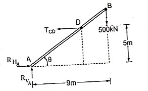
Applying conditions of equilibrium,
∑fx = 0
RHA – TCD = 0
RHA = TCD ------- (1)
∑fy = 0
RVA – 500 = 0
 RVA = 500 kN
Taking moment about point A,
∑MA = 0
-(TCD × 5 ) + (500 × 9) = 0
-TCD × 5 = -4500
TCD = 
 TCD = 900 kN
Putting the value in equation (1)
RHA = TCD
RHA = 900 kN
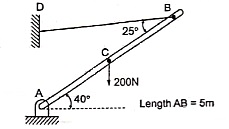
Que 7. A bar of weight 200 N is hinged at A and pulled by the string attached at B as shown in figure. The length of bar is 5m. Find the support reactions at A & corresponding tension in string.
 Consider triangle AEC
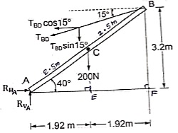


EC = 1.61 m
Consider triangle AEC

 AE = 1.92 m
Applying conditions of equilibrium
∑fX = 0
-TBD cos15 + RHA = 0 -------- (1)
∑fy = 0
RVA – 200 – TBD sin15 = 0
RVA – 200 – 0.26TBD = 0 ----------(2)
Taking moment at A
∑MA = 0
-(TBD cos15 × 3.2) + (TBD sin15 × 3.84) + (200 × 1.92) = 0
-3.09 TBD + 0.99 TBD + 384 = 0
-2.1 TBD = -384
 TBD = 182.86 N ---put in (1) & (2)
 RHA = TBD cos15 = 182.86 cos15
 RHA = 196.62 N
RVA = 200 + 0.26TBD = 200 + (0.26 × 182.86)
RVA = 247.54 N
Beam –
It is horizontal structural member on which different types of loads can be supported. It takes load from floor or roof & transfers to column.
The beam may be sometimes constructed in the inclined position for architectural point of view.
Types of Beam: -
- Simply supported beam –
A beam which is just resting on the supports at the end without any connection is known as simply supported beam. It is generally used for vertical landing system.

2. Overhanging Beam –
A beam which is supported at the intermediate point other than ends is called as overhanging beam. Here portion of beam is extended beyond the support
a)
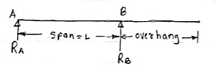
(singly overhanging beam)
b)

(doubly overhanging beam)
3. Cantilever Beam –
A beam which is fixed at one end is called as cantilever beam

Here, there are three reactions components:
- Vertical reaction at A (RVA)
- Horizontal reaction at A (RHA)
- Fixing moment at A (MA)
We can assume any direction for above components.
4. Continuous Beam:
A beam having more than two support is called as continuous beam.

5. Compound Beam:
When two or more beams are joined together by using internal hinge; or when one beam rests over another beam by using internal roller, then such beam is called as compound beam.
Types of loads on the Beam
- Point load
Load acting at a single point on the beam is known as point load. Its unit is N or kN

2. Uniformly Distributed load (UDL) or Rectangular Load:
A load which is spread over the beam or part of the beam uniformly is known as UDL
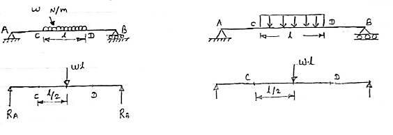
Conversion of UDL or Rectangular load into point load
= Intensity of UDL × distance
= w. l. ------------- N
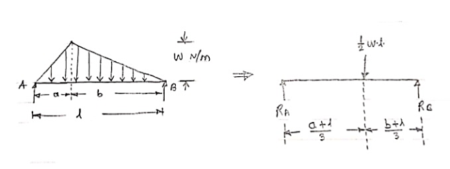
3. Uniformly varying load or Triangular load:
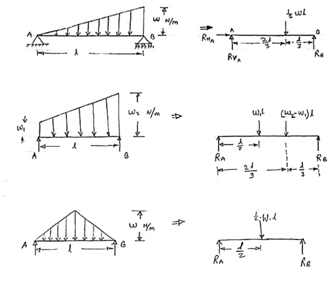
A load whose intensity is linearly varying between the two points on the beam is known as UVL. If an intensity of the load at one end is zero and at other ends is maximum, then it is called as uniformly varying load or triangular load.
Following figures shows different types of UVL
- To convert UVL into point load, calculate the area of uniformly varying load.
- For location of point load find x coordinate of centroid of the UVL area.
3.
Que 1. Find the support reactions of given beam for loading as shown below.
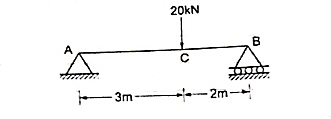
 Draw FBD of given beam & applying conditions of equilibrium
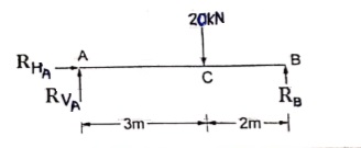
∑fx = 0
RHA = 0
∑fxy = 0
RVA – 20 + RB = 0
RVA + RB = 20 ------(1)
Taking moments at A
∑MA = 0
(20 × 3) – (RB × 5) = 0
60 – 5RB

RB = 12 kN  put in equation (1)
 RVA + 12 = 20
 RVA = 20-12
RVA = 8 kN 
Que. 2 Find support reaction for given beam
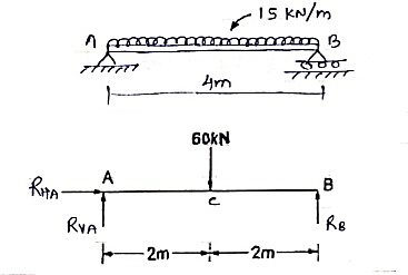
 Resolving forces horizontally
∑fx = 0
RHA = 0
Resolving forces vertically
∑fy = 0
RVA – 60 + RB = 0
RVA + RB = 60 -------(1)
Taking moment at A
∑MA = 0
(60 × 2) – (RB × 4 ) = 0
 120 – 4RB = 0
 RB =
RB = 
RB = 30 kN 
Que 3. Find the support reactions of a given loading for Beam.
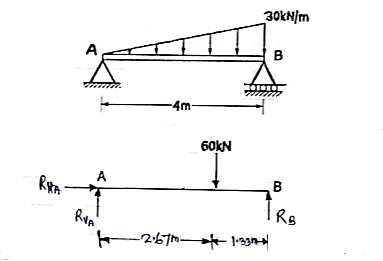
 Resolving forces horizontally
∑fX = 0
RHA = 0
Resolving forces vertically
∑fY = 0
RVA – 60 + RB = 0
RVA + RB = 60 ----------------- (1)
Taking moments at A
∑ MA = 0
(RVA × 0) + (60 × 2.67) – 4RB = 0
160.2 – 4RB = 0
 put in equation (1)
We get
RVA + 40 = 60
RVA = 60 – 40
RVA = 20 kN 
Que 4. Find the support reactions for given beam.
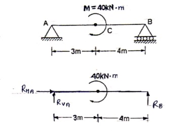
 Resolving force horizontally
∑fX = 0
RHA = 0
Resolving forces vertically
∑fy = 0
RVA + RB = 0 ---------------(1)
Taking moments at A
 40 – 7RB = 0
 RB =
RB = 
RB = 5.71 kN 
Put above value in equation (1)
RVA + RB = 0
RVA + 5.71 = 0
RVA = - 5.71 kN
RVA = 5.71 kN 
Resolving forces horizontally
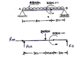
∑fX = 0
RHA = 0
Resolving forces vertically
∑fy = 0
RVA – 240 + RB = 0
RVA + RB = 240 --------------(1)
Taking moment at A
∑ MA = 0
(240 × 3) – 80 – 6RB = 0
640 – 6RB = 0
RB = 106.67 kN 
Put this value in equation (1)
RVA + RB = 240
RVA = 240 – 106.67
RVA = 133.33 kN 
Que 5. Find support reactions for the loading as shown below:
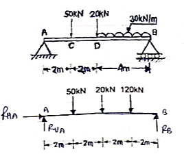
 Resolving forces vertically
∑fy = 0
RVA – 50 – 20 – 120 + RB = 0
RVA + RB = 190 --------------(1)
Resolving forces horizontally
∑fX = 0
RHA = 0
Taking moments at A
∑ MA = 0
(50 × 2) + (20 × 4) + (120 × 6) – 8RB = 0
100 + 80 + 720 – 8RB = 0
900 – 8RB = 0
RB – 112.5 kN 
Put above value in equation (1)
RVA + 112.50 = 190
RVA = 77.5 kN 
Que 6. Find the reactions at support A & B.
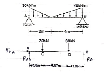
 Resolving forces vertically
∑fy = 0
RVA – 30 – 80 + RB = 0
RVA + RB = 110 --------------(1)
Resolving forces horizontally
∑fX = 0
RHA = 0
Taking moments at A
∑ MA = 0
(30 × 0.6) + [80 × (4.07 + 0.6)]- (6 × RB) = 0
18 + 373.6 – 6RB = 0
6RB = 391.6
RB= 65.267 kN
Put above value in equation (1)
RVA + RB = 110
RVA + 65.267 = 110
RVA = 110 – 65.267
RVA = 44.733 kN
Que 7. Find support reactions at A & B
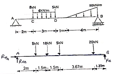
 Resolving forces vertically
∑fy = 0
RVA – 8 – 18 – 5 – 20 + RB = 0
RVA + RB = 51 --------------(1)
Resolving forces horizontally
∑fX = 0
RHA = 0
Taking moments at A
∑ MA = 0
(8 × 2) + (18 × 3.5 ) + (5 × 5 ) + (20 × 8.67) – 10RB = 0
16+ 63 + 25 + 173.4 – 10RB = 0
277.4 – 10RB = 0
RB = 27.74 kN
Put above value in equation (1)
RVA = 51 – 27.74
RVA = 23.26 kN
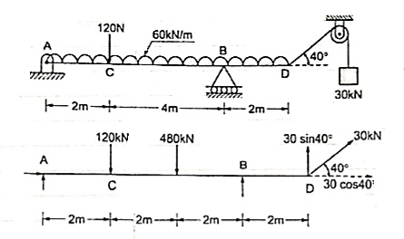
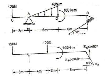
- The force system which is acting in different planes is called as non – coplanar force sys. Or space force.
- If a force is defined by three co-ordinates axis, then it is called as space force.
Rectangular components of force in space: -
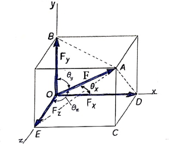
Let us consider the force F which is acting along the diagonal OA as shown above and making angles ØX, ØY, ØZ, with x,y,z axis respectively.
The above forces F in a three dimensional space can be resolved into rectangular components FX, FY, FZ.
Then
Fx = F cosØX
FY = F cosØy
FZ = F cosØZ

Here cosØX, cosØy , cosØZ are the cosines ofØX ,Øy , ØZ and are known as directions cosine of force F.
The force vector  can be expressed as ;
 = (FX i + FY j + FZ k)
 = (FcosØX i + FcosØy j + FcosØZ k)
 = F(cosØX i + cosØy j + cosØZ k)
 = F.
= F.
In above equation,
F = magnitude of force
 = unit vector along the direction of force.
 = (cosØX i + cosØy j + cosØZ k)
Here , cos2 ØX + cos2 ØY + cos2 ØZ = 1
Direction cosines can be found only by,
CosØX = 
CosØY = 
CosØZ = 
- When force F is defined in three dimensional space by using two points on its line of action, then rectangular components can be obtained as follows.
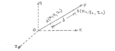
Consider force F acting at point O. Let A(x1,y1,z1)& B(x2,y2,z2) are the two points on the line of action of force F.
Let distance between two points (on the line of action of force) A & B is ‘d’.
Now
Vector  dx i + dy j + dz k
Magnitude of AB = d = 
We know that vector = magnitude × unit vector along AB
 AB
AB
 AB =
AB = 
 AB = (dx I + dy j + dz k) ×
We know that force  = magnitude x unit vector along line of action
 = F ×
= F ×  AB
AB
 =
=  (dx i + dy j + dz k)
 =
= 
From above equation we can have three components of force,
Fx = 
Fy = 
FZ = 
- Unit vector along direction of force
 AB =
AB = 
eAB = 
eAB =  unit vector
Position vector
- Consider force F passing through point Q (x2, y2, z2)
- Let P (x1, y1, z1) is point away from line of action.
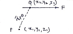
Then,
 PQ = position vector of P w.r.t. Q
= dx I + dy j + dz k
 PQ = (x2-x1)i + (y2 – y1)j + (z2-z1)k
r = 
Resultant of several forces in space: -
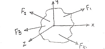
Consider a body on which forces F1 , F2 , F3 , F4 are acting as shown in figure.
R = Rx i + Ry j + Rz k
Rx = Resultant in x direction = ∑Fx = Fx1 + Fx2 + Fx3 + Fx4
Ry = Resultant in y direction = ∑Fy = Fy1 + Fy2 + Fy3 + Fy4
Rz = Resultant in z direction = ∑Fz = Fz1 + Fz2 + Fz3 + Fz4
R = 
Direction of resultant w.r.t. x,y,z axis is


- Moment of force in space about point
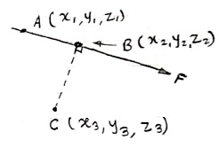
Consider a force  = Fx i + Fy j + Fz k is passing through two points A(x1, y1, z1) & B(x2, y2, z2) as shown.
Then moment of this force about point C(x3, y3, z3) will be
Mc =  CA ×
CA × 
Mc =| |
|
Here, [ rx = (x1 – x3), ry = (y1 – y3) & rz = (z1 – z3)]
Mx = (ryFZ - rZFZ)
My = (rZFX - rXFZ)
Mz = (rXFY - rYFX)
Mc = 
Moment of force in space about a line
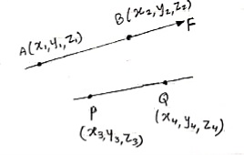
Consider the force of magnitude F passing through the points A(x1,y1,z1) & B(x2,y2,z2).
Consider any line passing through the points P(x3,y3,z3) & Q(x4,y4,z4)
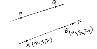
Moment of this force about line PQ is given by,
 =
=  .
. 
Rectangular components of force in space
- Fx = F cosØX
- FY = F cosØy
- FZ = F cosØZ
ØX = angle of force with x-axis
Øy = angle of force with y-axis
ØZ = angle of force with z-axis

Force vector (in space) :
 = (FX i + FY j + FZ k)
 = F ×
= F ×  AB
AB
 = unit vector along the direction of force.
eAB = 
- Moment of force in space about a point
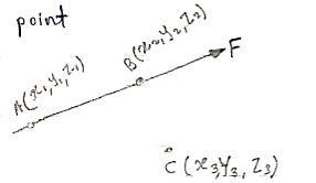
Moment of force F about point C is given by,
Mc =  CA ×
CA × 
Solving above equation we will get moment vector moment vector,
Mc = 
- Varignon’s theorem for forces in space
∑M = MR
Sum of moment of all forces = moment of resultant about
About a point same point
- Moment of Force about a line:
Key points: - moment of force will be zero if
- A line (about which moment is taken) is parallel to force
- If force intersects the line about which the moment is to be taken.
The moment of force about a line PQ is
 =
=  .
. 
Where, Mp =  PA ×
PA × 
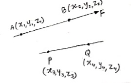
- Resultant of forces in space
RX = ∑FX = Fx1 + Fx2 + ……
RY = ∑FY = Fy1 + Fy2 + ……
RZ = ∑FZ = Fz1 + Fz2 + ……
R =  =
= 
Direction of resultant is;
Cosαx =  =
= 
Cos αy =  =
= 
Cos αz =  =
= 
- Equilibrium of concurrent & parallel forces in space:
 = 0
= 0  = 0
= 0
 = 0
= 0  = 0
= 0
 = 0
= 0  = 0
= 0
Numerical – concurrent forces in space (resultant &equilibrium)
Que 1. The cable exerts a force FAB = 100N & FAC = 120 N on the ring at point A as shown in figure. Determine the magnitude of the resultant force acting at A.
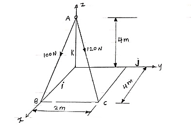
 Express the forces in terms of force vector
 = FAB ×
  AB
AB
= 100 
= 100
= 100
= 100(0.70 i + 0 j - 0.70 k)
= 70.7 i + 0 j – 70.7 k --------(1)
Now,
 AC = FAC ×
  AC
AC
= 120 
= 120
= 120
= 120(0.667 i + 0.333 j - 0.667 k)
= 80.04 i + 39.6 j – 80.04 k ----------(2)
From equation (1) & (2)
RX = ∑FX = 70.7 + 80.04 = 150.11 N
RY = ∑FY = 0 + 39.6 = 39.6 N
RZ = ∑FZ = -70.7 – 80.04 = -150.11 N
R = 
= 
R = 216 N
Direction of resultant is ;
αx = 
αy = 
αz = 
Que 2. If each cable can sustain a maximum tension of 600 N. Determine the greatest weight of bucket and its contents that can be supported. Refer the figure.
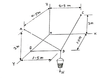
 Force developed in each cable will be tension, then, force vectors can be written as below,
(i)  DB = TDB ×
  DB
DB
= TDB
= TDB
= TDB(-1 i + 0 j + 0 k)
= - TDBi + 0 j + 0 k
(ii)  DA = TDA ×
  DA
DA
= TDA
= TDA
= TDA (- 0.333i + 0.667j + 0.677k)
= (- 0.333TDA )i + (0.677TDA) j + (0.667TDA)k
(iii)  DC = TDC ×
  DC
DC
= TDC
= TDC
= TDC (0.286 i –0.428 j + 0.857 k)
= (0.286TDC)i –(0.428TDC)j + (0.857TDC)k
(iv)  = -W.k = 0i + 0j – wk
Now applying equilibrium conditions,
∑Fx = 0
-TDB – 0.33 TDA + 0.286 TDC + 0 = 0 --------(1)
∑Fy = 0
0+ 0.667 TDA - 0.428 TDC + 0 = 0 --------(2)
∑Fz = 0
0+ 0.667 TDA + 0.857 TDC - w = 0 --------(3)
Now it is given that each cable can sustain maximum tension of 600 N. Thus our answer must be less than 600 or equal to 600 N.
(a) TDA = 600 N, then solving equation (1), (2) & (3) we get
TDB = 69.42 N
TDC = 935 N
W = 1201 N
Here tension in one cable is more than 600 N which is not allowed.
(b) TDB = 600 N , then solving equation (1), (2) & (3) we get
TDA = 5185 N
TDC = 8081 N
W = 10384 N
Here tension in the cables is more than 600 N which is not allowed.
(c) TDC = 600 N , then solving equation (1), (2) & (3) we get
TDB = 44.54 N
TDA = 385 N
W = 771 N
Here tension in each cable is less than 600 N. Thus this answer is correct
Weight of bucket = w = 771 N
Que 3. The ball is suspended from the horizontal ring using three springs each having stiffness of k = 50 N/m and an upstretched length of 1.5m. If h = 2m, determine the weight of ball. Refer the figure.

 The length of each spring is
L = 
L = 2.5 m
Unstretched length of spring
L0 = 1.5 m
Deflection of spring
X = L – L0 = 2.5 – 1.5
X = 1 m
Force developed in each spring = kx = 50×1 = 50N
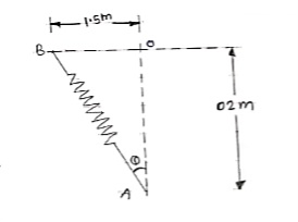
As shown in figure, each spring makes Ø angle with vertical
Sin Ø = 
Ø = 36.87 ˚
Y component of each spring force will be =
Fy = F cosØ = 50 cos 36.87 = 40 N
For equilibrium,
∑Fx = 0
-w + 3(Fy) = 0
-w + 3 × 40 = 0
W = 120 N ---------- weight of ball
Numerical – Parallel forces in space (resultant and equilibrium)
Que 1. Determine the magnitude and direction of resultant force of given force system as shown in figure & locate its point application on the slab. (Dec 15)
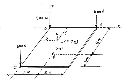
 Let resultant acts at point D (x,y,0)
In above case, we can observe that all forces are parallel to each other & are parallel to z-axis. Therefore
Rx = ∑Fx = 0 &
Ry = ∑Fy = 0 &
Rz = ∑Fz = - 500 – 400 – 100 – 600 = -1600 N
Resultant = R = 
R = 1600 N 
Resultant is parallel to z-axis
Now to find the location of resultant assume that R is acting at point D on the slab.
D(x,y,0)
By using varingnon’s theorem about x-x axis.
∑MXX = MRX
(100 × 6) + (600 × 8) = (R.y)
600 + 4800 = 1600 y
Y = 3.375 m
By using varingnon’s theorem about y-y axis,
∑MYY = MRY
-(400 × 10) – (100 × 5) = -(R.x)
-4000 – 500 = -1600x
x = 2.81 m
The resultant will alt at point
D(2.81, 3.375, 0)
Que 2. Determine the resultant of parallel force system which acts on the plate as shown in figure.
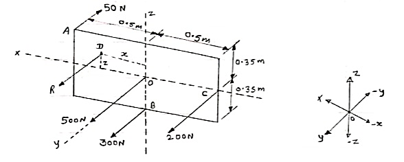
 Let us assume that resultant is acting at point D(x,0,z)
Here all forces are parallel to y-axis, so their x & z components are zero.
Rx = ∑Fx = 0
Rz = ∑Fz = 0
Ry = ∑Fy = - 50 + 500 + 300 + 200 = 950 N
Resultant = R = 
R = 950 N (parallel to +ve y-axis)
To find the position of resultant, let us use varingnon’s theorem
By using varingnon’s theorem about x-x axis;
We have
∑MXX = MRX
(300 × 0.35) + (50 × 0.35) = (-R.z)
105 + 17.5 = -(950 × z)
Z = 0.129 m
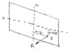
By using varingnon’s theorem about z-z axis
∑MZZ = MRZ
-(50 × 0.5) – (200 × 0.5) = R.x
-25 – 100 = 950.x
x = - 0.131 m
This resultant will act as shown in the figure on the right.
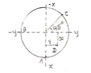
Que 3. Three parallel bolting forces act on the rim of the circular cover plate as shown in figure determine the magnitude & direction of resultant, point of application of resultant.
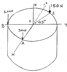
 As all forces are parallel to each other & to z-axis, resultant is given by
Rx = ∑Fx = 0
Ry = ∑Fy = 0
Rz = ∑Fz = -200 -150 – 300 = - 650 N
R =  = 650 N
  Parallel to z-axis
Now
Assume, that resultant is acting at point D (x,y,0)
Using varingnon’s theorem about x-x axis
∑MXX = MRX
(200 × r) + (150 × r cos45) = -650y
Y = -0.145 m
By using varingnon’s theorem about y axis
∑MYY = MRY
(300 × r) – (150 × r sin45) = 650x
x = 0.298 m
Point of application of resultant D(0.298, -0.145, 0)
Que 4. Four parallel bolting forces act on the rim of the circular cover plate as shown in figure. If the resultant force 750 N is passing through (0.15 m, -0.1 m) from the origin O, determine the magnitude of forces P1 & P2.
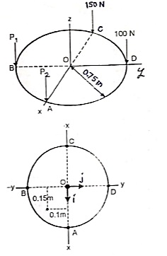
 As all forces are parallel to z-axis the resultant can be find out by,
R = ∑Fz
-750 = -P1 – P2 – 150 – 100
-750 + 150 + 100 = -P1 – P2
P1 + P2 = 500 ------------(1)
Now using varingnon’s theorem about x-x axis
∑MXX = MRX
(P1 × 0.75) - (100 × 0.75) = -Ry
0.75P1 – 75 = -[750 × (- 0.1)]
0.75P1 – 75 = 75
0.75P1 = 75 + 75 = 150
P1 = 200 N 
From equation (1)
P1 + P2 = 500
200 + P2 = 500
P2 = 500 – 200
P2 = 300 N 
Que 5. Three parallel bolting forces act on the rim of the circular cover plate as shown in fig. Determine the magnitude, nature and point of application of the resultant force with respect to O.
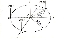
 As all the forces are parallel to z-axis, their x & y components are zero. Thus
∑Fx = 0
∑Fy = 0
∑Fz = -200 – 150 – 300 = - 650 N
R = 
As ∑Fx = ∑Fy = 0
R = ∑Fz = -650 N
R = 650 N  parallel to z-axis
Assume that resultant acts at point D (x,y,0)
Using varingnon’s theorem about x-x axis
∑MXX = MRX
(200 × 0.8) - (150 × 0.8 cos45) = -Ry
160 – 84.85 = -650.y
y = -0.115 m
By using varingnon’s theorem about y axis
∑MYY = MRY
(300 × 0.8) – (150 × 0.8 sin45) = R.x
240 – 84.85 = 650.x
X = 0.206 m
Resultant acts at point D(0.206, -0.115, 0)
References:
1. Engineering Mechanics by S. P. Timoshenko and D. H. Young, McGraw- Hill publication
2. Engineering Mechanics by J. L. Meriam and Craige, John Willey
3. Engineering Mechanics by F L Singer, Harper and Rowe publication
4. Engineering Mechanics by A. P. Boresi and R. J. Schmidt, Brooks/Cole Publication