UNIT - 3
Stability Analysis
In digital control systems, the controller operation is implemented digitally. In the majority of control applications, however, the plant is an analog system. Digital control then results in hybrid systems, i.e., systems having both continuous-time and discrete-time parts. Such systems are also referred to as sampled data systems (SDS). Here the controller consists of three subsystems: a sampler, a digital controller and a so-called hold device.

Fig: Sampled Data controller
The nth order differential equation of LTI discrete data system can be represented as
y(k+n) +an-1y(k+n-1) +an-2y(k+n-2) +…. +a1y(k+1) +a0y(k)=bmx(k+m) +bm-1x(k+m-1) +…. +b0x(k)
x(k) and y(k) are the inputs and outputs of the system respectively. The z-transform can be obtained as
H(z)=Y(z)/X(z)
H(z)= (i)
(i)
The characteristic equation is obtained by equating the denominator to zero
 =0
=0
Que) G(s)=2/s(s+2). Find the characteristic equation for the transfer function H(z) with unity feedback. Let T=0.2sec?
Sol: G(s)=
Finding G(z)= z[ ]
]
= =
= (T=0.2sec)
Hence, the characteristic equation will be
1+G(z)H(z)=0
But there is unity feedback so
1+G(z)=0
1+ =0
=0
z2-1.34z+0.67=0
The required characteristic equation is z2-1.34z+0.67=0
• In a causal system, the output does not precede the input. In other words, in a causal system, the output depends only on the past and present inputs, not on the future ones.
• The transfer function of a causal system is physically realizable, i.e., the system can be realized by using physical elements.
• For a causal discrete data system, the power series expansion of its transfer function must not contain any positive power in z. Positive power in z indicates prediction. Therefore, in the transfer function (i), n must be greater than or equal to m.
A digital filter is a system that performs mathematical operations on a discrete and sampled time signal, so as to enhance or reduce certain aspects of that particular signal as may be necessary. It is largely used in signal processing and differs from an analog filter, which is an electronic circuit working with continuous signals. Digital filters are expensive compared to analog ones, but they can turn many impractical or impossible designs into possibilities.
Digital filters are used for two general purpose
1) Separation of signals that have been combined.
2) Restoration of signals that have been distorted in some way.
Analog filters can also be used for same purpose but digital filters show superior results.
The realization of theses digital filters is discussed in section 3.5
The basic realisation techniques used for filters are direct form, cascade form and parallel form. In this section we will study all in detail. This section overviews ability to implement finite impulse response (FIR) and infinite impulse response (IIR) filters using different structures in terms of block diagram and signal flow graph.
For an LTI system the transfer function is given as
H(z)=  (1)
(1)
The difference equation can be written as
 (2)
(2)
x(n)= system input
y(n)=system output
When a0≠ (3)
(3)
The above equation implementation requires some basic blocks shown below
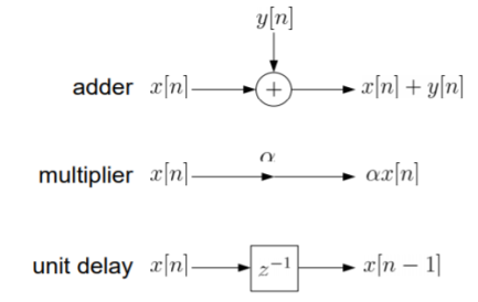
Fig: Block diagram representation
The above blocks can be easily understood with the help of one example. For the standard LTI system with difference equation
Y[n]=-a1y[n-1]-a2y[n-2]+b0x[n]. Draw the block diagram for the given equation.
Sol: We already know that x[n] and y[n] are the input and output to the system respectively.
- If we need the term y[n-1] we need a delay block after y[n], and one more delay block after y[n-1] to get y[n-2].
- For getting term -a1y[n-1] we need multiplier of -a1and same for -a2.
- To get complete term -a1y[n-1]-a2y[n-2]+b0x[n] we need adders so that the we get the final equation.
- The final figure using 2 adders, 3 multipliers and 2 delay blocks is shown below.
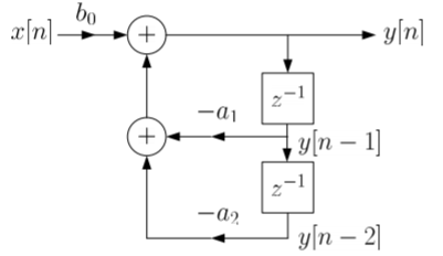
Fig: Block diagram representation
FIR FILTER:
The standard equation for representing the FIR filter is shown below
H(z)= (4)
(4)
From equation (1) and (4) we can conclude that FIR filters do not contain any pole. The difference equation will be
Y[n]=  (5)
(5)
a) Direct Form:
The direct form is directly derived from the difference equation. It can be represented as
y[n]=  (6)
(6)
Where h(k) is the system impulse response.
Expanding the above equation, we get
Y[n]= =h[0]x[n]+h[1]x[n-1]+……h[M]x[n-M] (7)
The block diagram representation for above direct form is shown below.

Fig: Direct form realisation of Fir filter
b) Cascade Form:
As we already know H(z)=
The above equation can be represented as a product of second order polynomial as
H(z)= =
= (8)
(8)
Mc=|(M+1)/2|
The above equation can be further simplified with intermediate output of system 1 w1(n) fed to the input of second cascade structure and so on.
The difference equation is given as
w1(n)=  +
+ (9)
(9)
w2(n)=  +
+ (10)
(10)

Fig: Cascade form FIR filter
EXAMPLE
IIR FILTER:
The transfer function of IIR filter is given as
H(z)=  (11)
(11)
From above equation we can conclude that an IIR filter contains at least one pole.
a) Direct Form:
The direct form is realised directly from its difference equation
v[n]=  (12)
(12)
y[n]=-  +v[n] (13)
Another way to obtain direct form is by decomposing H(z) into two transfer functions
H(z)=H1(Z). H2(z)
H1(Z)=  (14)
(14)
H2(z)=  (15)
(15)
V(z)=X(z). H1(Z)=X(z) (16)
(16)
Y(z)=V(z). H2(z)=V(z) (17)
(17)
The final realisation block diagram representation of direct form for IIR filter is shown below
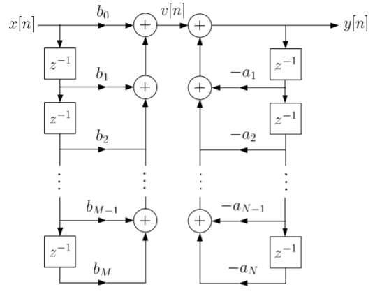
Fig: Direct Form realisation of IIR Filter
b) Cascade form:
To find the transfer function for cascade for we need to factorise the numerator and denominator polynomials in terms of second order polynomial.
H(z)= =
= (18)
(18)
Nc=|(N+1)/2|
Let us consider M=N=4. Then the cascade realisation for IIR filter is shown below.
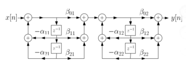
Fig: Cascade Form realisation of IIR Filter
Que) For the following LTI system H(z)= . Realise the cascade form IIR filter.
Sol: H(z)=
The above function can be simplified as
H(z)=
Hence, using the above structure and placing the values of 
 …. And similarly,
c) Parallel form:
The parallel form is given as H(z)= +
+ (19)
(19)
Nc=(N=2)/2
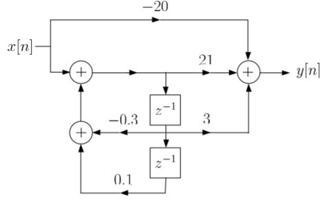
Que) Draw block diagram for the function using parallel form H(z)=
Sol: H(z)=
Writing above transfer function in standard form for parallel realisation we get
H(z)=-20+
The structure is shown below
Let us consider a discrete signal r(t) having discrete values r(nT) at sampling rate of 1/T. The z-transform is given as
R(z)=
If the signal is impulse sampled then
R*(t)=
Taking Laplace Transform
R*(s)=
Let z=
S=1/T ln z (a)
R*(s)|s = 1/T ln z =R(z) (b)
Equation (a) maps the s-plane to z-plane
z=
=
Where  =
= /T
/T
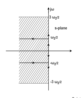
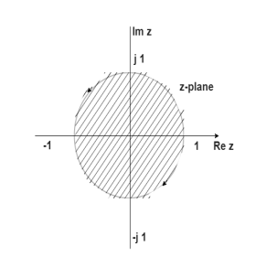
The figure above shows that every section of j -axis maps into the unit circle. The strips of the left half of s-plane are mapped into interior of the unit circle. In s-plane the stability depends on the position of poles, all the poles on left half of s-plane makes the system stable. Now, in z-plane all the poles on left half of s-plane should lie within the unit circle making the system stable.
i) Jury’s Test: It is an algebraic criterion for determining whether or not the roots of the characteristic polynomial lie within a unit circle.
Let the characteristic polynomial be
F1(z)=anzn+an-1zn-1+….+a0=0 for an>0
This test consists of two parts i) Test for necessary condition ii) Test for sufficiency
The necessary condition is F1(1)>0
For sufficient condition we follow the below given method.
a) Make a table of coefficients of the characteristic equations
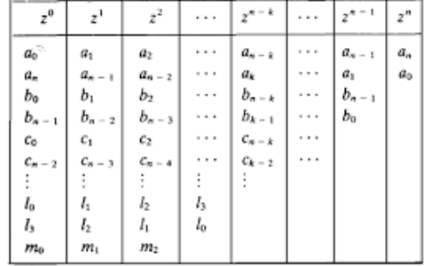
Where
bk=
ck=
dk=
The sufficient conditions for stability are
| |<|
|<|
| |>|
|>|
| |>|
|>|
.
.
.
| >|
>| |
|
Q) Consider the characteristic equation of the second-order system F1(z)=a2z2+a1z+a0=0 for a2>0. The stability constrains will be?
Sol: F1(z=1)=a2+a1+a0 >0
(-1)n F1(z=-1)= a2-a1+a0 >0
| |<
|< 
Ii) Bilinear Transformation:
In z-domain for the system to be stable the roots of the characteristic equation must lie within the unit circle. But the transform z=esT cannot be used because the periodicity of esT and multiple strips of left half of s-plane into which the interior of the unit circle maps.
The Bilinear transformation maps the interior of the unit circle in the z-plane into the left half of r-plane.
r=
z=
On the unit circle in the z-plane
 z=
z=
 - 180
- 180 to +180
r= =
= =tanhj
 =jtan
=jtan =j
=j r
r
 r= tan
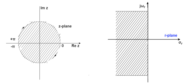
The characteristic equation is
an + an-1
  +………..+a1
 +a0=0
+a0=0
Q) Using bilinear transformation determine the characteristic equation of given open loop function in z-plane. G(s)=
Sol: G(s)=
=5[  ]
]
=5[  ]
]
=
The characteristic equation is given as
1+G(S)= +
+ =0
=0
z3-0.5z2+2.49z-0.496=0
Putting in equation below
The characteristic equation is
an + an-1
  +………..+a1
 +a0=0
+a0=0
 -0.5
-0.5 +2.49
+2.49 -0.496=0
The system stability can be checked using Routh array
The characteristic equation in s-domain will be
1+G(s)=0
1+ =0
=0
s3+3s2+2s+5=0
s3 1 2
s2 3 5
s1 1/3 0
s0 5 0
First column no sign change. Hence, system is stable.