Unit -III
Programming of PLC
Logic | Result if signal state of contact is 1 | Result if signal state of contact is |
Normally open (No) | Power can flow because normally open contact is closed | Power cannot flow because normally open contact is open |
Normally closed (Nc) | Power cannot flow because normally closed contact is opened | Power can flow because normally closed contact is closed |
Input and output contact programs symbols
The program symbols for a PLC input will look like a normally open or normally closed contact used in electrical diagrams.
The output instruction is  i.e. output energize. This is used in a letter program to turn on a bit when circuit condition is evaluated as true.
It is seen that the PLC allows one real switch to control hundreds of programs contact as shown in following figure.
The maximum number of contacts the real switch can control will be limited by the processor memory size.
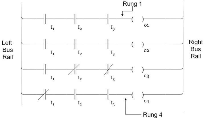
Each ring is a program statement. a program statement consists of a condition or conditions along with some type of actions. Input are the conditions and action for the output is the result of these conditions. Each ring of the PLC ladder can be looked at as a problem the processor has to solve.
Numbering systems of inputs and outputs
The input and output terminals are grouped together and placed in modules. Each of the manufacturer produces a variety of input and output module. Since the Programmable controlled may have hundreds of input or output modules, it is important to have some kind of numbering system to identify each module and all its input and output terminals.
The generalized identification numbering system of input and output terminals of a PLC consist of the following parameters
Input / Output -module number-Rack number-slot number-word number-terminal number.
The Allen Bradley numbering system is γ : e s l b.
The meaning of each character has been shown.
γ | : | e | . | 5 | l | b |
γ=0 for o/p γ=1 for input | Element delimiter | Slot number-adjacent to the power supply in the first classes, applies to the processor module (CPU) succeeding slots are input it and output slots numbered form 1 to a maximum of 30. | Word delimiter required only if a word number is necessary | Word number required if the input or output exceed i.e. for the slot range 0-255 | Bit delimiter | Terminal number 0-15 Output 0-15 |
Rails – There are two rails in a ladder diagram which are drawn as vertical lines running down the far most ends of the page. If they were in a relay logic circuit they would represent the active and zero volt connections of the power supply where the power flow goes from the left hand side to the right hand side.
Rungs – The rungs are drawn as horizontal lines and connect the rails to the logic expressions. If they were in a relay logic circuit they would represent the wires that connect the power supply to the switching and relay components.
Inputs – The inputs are external control actions such as a push button being pressed or a limit switch being triggered. The inputs are actually hardwired to the PLC terminals and represented in the ladder diagram by a normally open (NO) or normally closed (NC) contact symbol.
Outputs – The outputs are external devices that being are turned on and off such as an electric motor or a solenoid valve. The outputs are also hardwired to the PLC terminals and are represented in the ladder diagram by a relay coil symbol.
Logic Expressions – The logic expressions are used in combination with the inputs and outputs to formulate the desired control operations.
Address Notation & Tag Names – The address notation describes the input, output and logic expression memory addressing structure of the PLC. The tag names are the descriptions allocated to the addresses.
Comments – Last but by not least, the comments are an extremely important part of a ladder diagram. Comments are displayed at the start of each rung and are used to describe the logical expressions and control operations that the rung, or groups of rungs, are executing. Understanding ladder diagrams is made a lot easier by using comments.
1. The power will flow from the left hand side bus rail to the right hand side bus rail.
2. Each ring must start with a contact from the left and end with an output on the right.
3. Output cannot be connected to the left bus rail.
4. Contacts cannot be connected to the right bus rail.
5. Only one output may be placed on each ring.
6. Each output can be used once in a program.
7. Input with the same terminal number can be used many times.
8. Input address can be used in serial or parallel
9. Output address can be used in parallel.
10. Output address can be used as input address.
11. Input address not to be used as output address.
12. Input it address can be repeated as input address.
Introduction to logic:-
1)Equivalent ladder diagram of AND gate:-
Truth table:
Control signal | Control signal | Output |
C1(I:0/1) | C2(I:0/2) | γ(0:0/1) |
0 | 0 | 0 |
0 | 1 | 0 |
1 | 0 | 0 |
1 | 1 | 1 |
The Boolean expression is written as Y=A:B
The output is high only when the input is high. Therefore AND gate is equivalent to a series combination of normally open switch is in a ladder as shown.

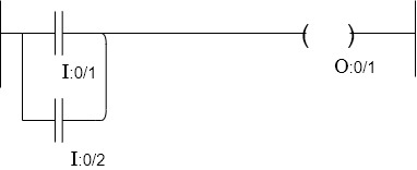
2)OR Gate
Boolean expression Y= A+B
C1 (I: 0/1) | C2 (I:0/2) | Y(0:011) |
0 | 0 | 0 |
0 | 1 | 1 |
1 | 0 | 1 |
1 | 1 | 1 |

3)NOT Gate:-
C1 (I:0/1) | Y 0: O/I |
0 | 1 |
1 | 0 |
Boolean expression 


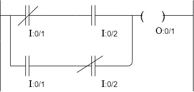
4)XOR Gates:-
Boolean expression Y=AB+
C1 (I: 0/1) | C2(I:0/2) | Y (0:0/1) |
0 | 0 | 0 |
0 | 1 | 1 |
1 | 0 | 1 |
1 | 1 | 0 |

5) NAND Gate :-
C1(I:0/1) | C2(I:0/2) | C3(0:0/1) |
0 | 0 | 1 |
0 | 1 | 1 |
1 | 0 | 1 |
1 | 1 | 0 |

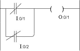
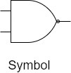
6) NOR Gate:-
C1 (I:0/1) | C2 (I:0/2) | Y(0:0/1) |
0 | 0 | 1 |
0 | 1 | 0 |
1 | 0 | 0 |
1 | 1 | 0 |


Switches:-
1)Push button:
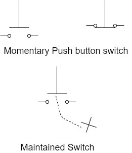
i. The most common switch is the push button.
Ii. There are two types of push buttons – Momentary and Maintained
Iii. The momentary push button switch is activated when the button is pressed and deactivated when the button is released.
Iv. The deactivation is done using an internal
v. The maintained push button switch activates when pressed but remains activated when it is released.
Vi. To deactivate it, it must be pressed a second.
Vii. For this reason this type of switch is sometime called push switch.
2)Push button switch actuators:-
The actuator of push button is the part of switch that is depressed to activate the switch
1. In the Guarded actuator the push button is inside the sleeve and can only be depressed and object smaller than the sleeve.
2. It provides protection against the push button being accidentally depressed by the palm of the hand or other object and is therefore used in situations where pressing the switch causes something potentially dangerous to happen.
3. Guarded push buttons are used in applications such as START, RUN,CYCLE,JOG or RESET operations.
4. The flush push button has an actuated that is aligned to be even with the sleeve. It provides protection against accidental actuation similar to the guarded pushbutton. However since it is not recessed, the level of protection is not to the extent of the guarded pushbutton.
5. In extended push button the actuator extend beyond the sleeve, which makes the button easy to depress by finger, palm of the hand or any other object.
6. It is intended for applications where it is desirable to make the switch as assessable as possible such as STOP, PAUSE or Brakes.
7. In extended pushbutton, when pressed in IT remains in and then to return it to its original position it must be pulled out and is called as Emergency stop or E stop switch.
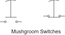
8. The mushroom head is always read and this which is used to shut off power to the controls of the machine when the switches pressed in.
9. In order to restart machine, E stop switch must be post to the out position to apply power to the controls before attempting to run the machine.
10. Mushroom head switches have special schematic symbols as shown below. Notice that they are drawn as standard push button switches but have a curved line on the top of the equator to indicate that the equators have a mushroom head.
3)Selector switches:-
i. A selector switch is also known as the rotary switch. An automobile ignition switch is an example of selector switch.
Ii. Selector switch is used the same symbol as a momentary push button accept a lever is added to the top of the actuated as shown
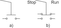
Iii. The switch in figure (a) is open when the selected is turned to left and close when turn to the right.
Iv. The switch in figure (b) has two sets of contact. The top contacts are closed when the switch selector is turned to the left position and open when the selector is turned to the right.
v. The bottom set of contacts work exactly opposite.
Vi. There is no electrical connection between the top and bottom pairs of contacts.
4)Limit switches:-
i. Normally limit switches are not operator accessible. Intended , they are activated by moving parts on the machine.
Ii. They are usually mechanical switches but can also be light activated (such as automatic door openers used by stores and supermarkets ) or magnetically operated (such as the magnetic switch is used on home security systems that sense when a window has been opened).
III, An example of a mechanical operated limit switch is the switch on the refrigerator door that turns on the light inside.
IV. Are sometimes called cam switch is because many are operated by a chemical reaction when a moving part pass by the switch.
V. The symbol for both types of limit switches are shown in figure.

Timers:-
A timer is a device that introduces a time delay in a circuit or a system during its ON/OFF condition.
The schematic diagram of a function block PLC timer is shown in figure.
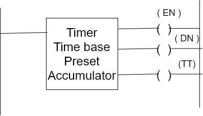
A timer function block has three output contacts. When the timer is timed out Bit (ON) is set. The enable bit follows the input enable contact status. If the enable contact is true then output enable bit (EB) is true. The timer timing (TT) bit is set when the timer is operating.
Functions of a timer:-
One out standing feature of Programmable time is the variety of time base available. The most common time basis is 0.01 second, 0.1 second and 1 second interval.
Accumulator value (ACC):- This is the time that has clasped. Since the timer was last reset when enable a timer updates this continuously.
Preset value (PRE):- this specifies the value that the timer must reach before the controller sets the tone bit. The programmer detect the preset time. When the accumulator value becomes equal to or greater than the present value the timer starts operating and done bit is set. This that can be used to control and output device. Preset and accumulator due for timer range from 0 to +32;767. If a timer reset on accumulator value is a negative number, a runtime error occurs.
Resetting, Retentive and Non Retentive:-
i) When a accumulator value of a timer is 0, it is said to be in the recent condition.
Ii) When the timer’s accumulator value RV set to 0 its time the input enable contact is open, it is said to be non-retentive timer.
Iii) The timer does not retain or remember the accumulator value when the enable contact are opened.
Iv) There may be times in an industrial process when one wants to retain the the timer or remember the accumulator value the timer has reached even though the enabled contacts are opened.
v) For instance, a person wants to keep track of the total running time of motor over one year.
Vi) The motor may only run 3 or 4 hours a day and may turn on and off several times.
Vii) Retentive timer does not reset its accumulator value to zero its enable contacts opened.
Viii) Instead it remembers or retains its accumulative value.
Ix) Opening it enable contact may stops the timer from running. In order to reset the retentive timer reset instruction is used.
Timer ON Delay :-
i) This instruction is used to delay turning and output on or off.
Ii) The ON instruction begin to count time base intervals when the rung condition become true.
Iii) As long as the rung condition remains true to the timer increments its accumulator value over each scan until it reaches the preset value.
Iv) The accumulator value is reset when the rung condition becomes false, regardless of whether the timer has timeout.
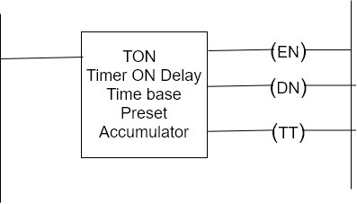
Output bit | Is set when | Remains set until |
(DN) | Accumulator value is normally greater than preset value. | Rung condition becomes false. |
(EN) | Rung condition are true | Rang conditions becomes false |
(TT) | Rung conditions are true values are less than preset value | Rung condition becomes falls on when the done bit is set |
Timer OFF Delay:-
i) This instruction is used to delay turning an output on or off.
Ii) The TOF instruction begins to count time base intervals when the rung condition makes a true to false transmission.
Iii) As long as the rung condition remains false the timer increments its accumulator value over its can until it reaches the preset value.
Iv) The controller resets the accumulated value when the rung condition becomes true regardless of whether the timer has timed out.
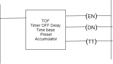
Output bit | Is set when | Remains set until |
DN | Rung conditions are true | Rung condition became false and the accumulator value is greater than equal to the present value |
TT | Rung condition are false and the accumulator value is less than the present value | Ran conditions became false or when the done bit is set |
EN | Rung condition are true | Rung conditions becomes false |
Problems:-
1. Draw a ladder diagram for a two motor system having the following conditions.
a) Starting push button starts motor-1.
b) After 10 seconds motor 2 is ON.
c) Stopping 10 which stops motor 1 and 2
Time base= 1 second
Input;
Start=I:0/10
Stop=I:0/1
Output;
M1=0:0/1
M2=0:0/2
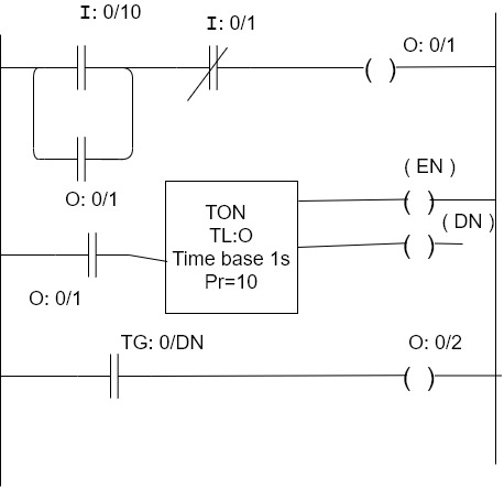
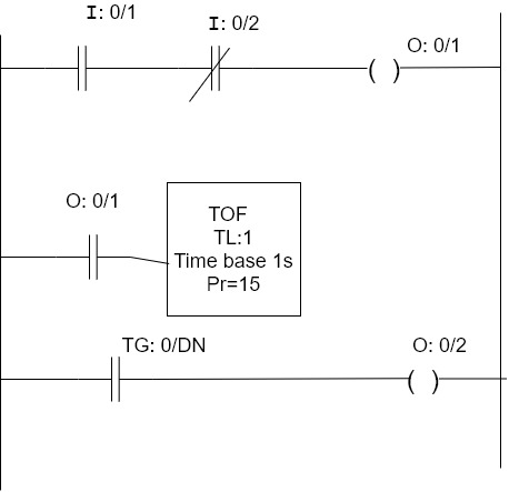
2) Draw the ladder diagram for a two motor system having following conditions
i) The start switch start motor 1 and 2
Ii) The stops which stops motor 1 first after 15 seconds motor 2 stops.
Input;
Start=I:0/1
Stop=I:0/2
Output;
M1=0:0/1
M2=0:0/2
3)Draw a ladder diagram for a two-motor system having the following conditions
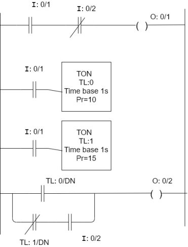
The states which starts motor 1 and 10 seconds later motor 2 starts. The stops which stops motor 1 and 15 seconds later motor 2 stops.
Input
Start=I:0/1
Stop=I:0/2
Output
M1=0:0/1
M2=0:0/2
4)Draw a ladder diagram for a three-motor system having the following conditions
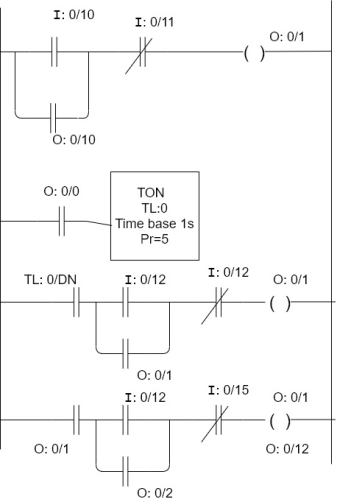
Motor 2 (M2) can start five seconds after motor 1 (M1) starts, when M2 is running, motor (M3) can be started. When M2 is turned off, M3 is off. When M1 is turned off, both M2 and M3 stops.
Input
Start=I:0/10
Stop=I:0/11. For M1
Start= I:0/12
Stop=I:0/13. For M2
Start=I:0/12
Stop=I:0/15. For M3
Output
M1 0:010
M2 0:011
M3 0.012
5)Draw a ladder diagram for a three-motor system having the following conditions
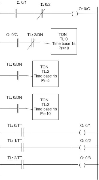
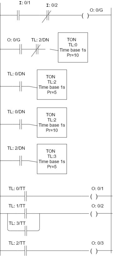
Motor (M1) starts as soon as the start switch is on. After 1 second, M1 goes off and motor 2 (M2) starts. After 5 seconds M2 goes off and M3 starts after 10 seconds, M3 goes off, M1 starts and the cycle is repeated.
Input
Start=I:0/1
Stop=I:0/2
Output
M1= 0:011
M2=0:012
M3=0:013
System= 0:014
6)Draw a ladder diagram for a three-motor system having following conditions. Motor 1 (M1) starts as soon as the start switch is on, after 10 seconds, M1 goes off and M2 starts. After 5 seconds M2 goes off and M3 comes on. And after 5 seconds M2 goes off and M1 comes on and the cycle is repeated.
Input;
Start=I:011
Stop=I:012
Output;
M1=0:011
M2=0:012
M3=0:013
System = 0:016
The SET coil is switched on when power is supplied to it and remains set until it is RESET. The RESET coil is reset to the off state when power is supplied to it and remains off until it is SET.
A Master Control Reset (MCR) instruction is an output instruction. MCR instructions are always used in pair.


The paired instructions cause the PLC to enable or inhibit a zone of ladder logic program outputs according the application logic. The zone being controlled is known as the MCR zone control. It begins with the rung that has the first MCR instruction. The MCR zone ends with the rung that has the second MCR instruction only.
Using this instruction, we can disable all the outputs at the same when MCR condition goes off.
Two MCR instruction are used to perform the function, one is to start the MCR zone with input condition as must and another one is to end the limit area.
An input condition like Emergency switch is programmed on the rung of the first MCR to control rung logic continuity. When the rung goes “false” all non-retentive outputs within the controlled zone are disabled. When the rung goes “true” all rungs are scanned according to their normal rung conditions.
No need to give any condition for closing MCR zone.
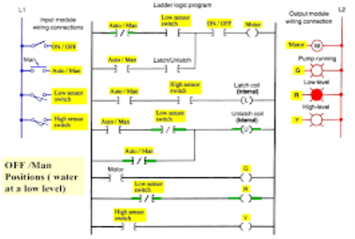
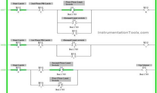
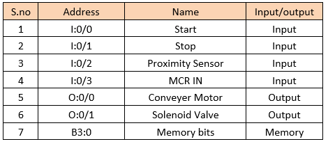
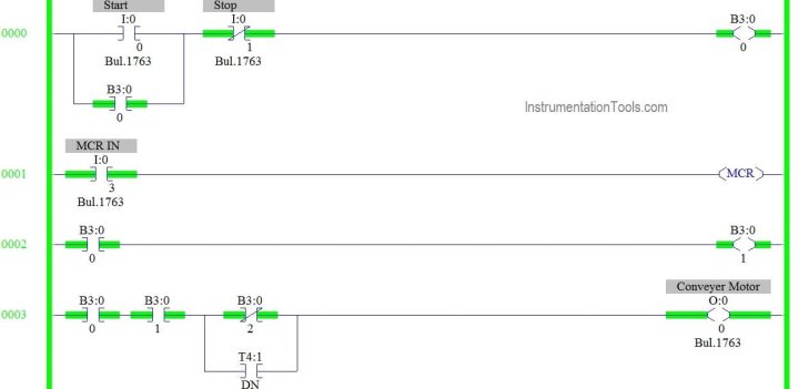
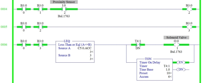
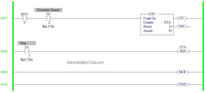
- Start and Stop PB is used to start and stop the process.
- MCR zone need to activated to start the process
- Start is pressed Conveyor starts moving until the Proximity Sensor is ON.
- Then solenoid valve is open for 5s. After 5s Conveyor should start moving.
- The above process should continue unto 3 bottles.
- Process should continue still stop push button pressed.
- In any emergency case, MCR condition goes off, all output disabled irrespective of its input.
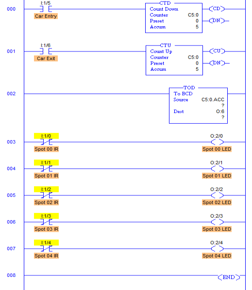
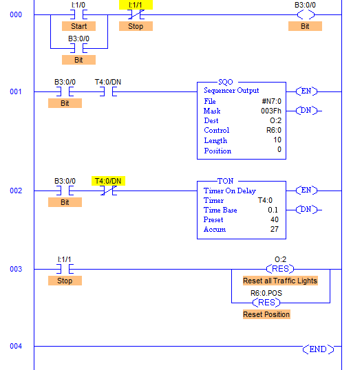
List of Inputs and Outputs
PLC Program
PLC counter
1) In the manufacturing process industry it is always necessary to count the number of items producers and the number of operations performed. In such operations counters are used.
2) An electro mechanical counter comprises solenoids springs, lever mechanism etc. for accounting and action and recording it.
3) this has the disadvantage that failure of any part of the counter leads to errors in its readings.
4) On the other hand a counter in a PLC utilizes a sensor to count it operations which is processed by software execution in the PLC.
5) Thus the failure rate is reduced and the accuracy level is increased in a PLC counter.
6) The range of count of a PLC counter is much larger than that of an electromechanical counter.
Operation of PLC counter:-
1) The counter instruction operates in a similar manner to those of the timer instruction in the PLC.
2) the major difference between the counter and the timer is that timer instruction will continuously increment its accumulated value at rate determined by the time base when the enable contact is on.
3) On the other hand, the counter must complete contact transmission from 0 to 1 each time it increments the accumulator value.
4) This means that the contact must return to its zero state before it can have a transmission for a second time.
5) In encounter the contact can stay closed for any amount of time after a transition what is important is that the transition has taken place.
Counter parameters
In general, a PLC counter has two parameters
a) The accumulator value (ACC)
b) Preset value (PRE)
a) The accumulator value (ACC) is the number of false- to-true transmission that have occurred since the counter was last reset.
b) The preset value (PRE) specifies the value that the counter must reach before the control sets the done bit.
c) when the accumulator value becomes equal to or greater than the present value the dance status bit is set. This can be used to control and output device.
Overview of counter instructions
1) Each counter address is made up of a 3- word data file element.
2) Word 'O' is the control word continuing status bits of the instruction, word 1 is the preset value and word 2 is the accumulated value.
The addressing format is shown in table
C | f | : | e |
Counter file | File number Typical file number is 5. | Element Delimiter | Element number (Ranges from 0 to 39) |
Account VP (CTU)
1) The CTU is an instruction that counts false-to-true rung transitions.
2) Rung transition can be caused by events occurring in the program (from internal logic or by external field devices)
3) When the rung condition for a CTU instruction has made a false to true to transition the accumulated value increment by 1 count. Provided that, the rung containing the CTU instruction is evaluate between these transitions.
4) Visibility of a counter to detect a false-to-true transition depends on the speed (frequency) of the incoming signal.
5) The on and off duration of an incoming signal must not be faster than the scan time.
6) The accumulator value is retained when the rung condition again becomes false.
7) The accumulated account is retained until cleared by a reset (RES) instruction that has the same address as the counter reset.
8) The accumulator value is written after the CTU instruction became false or when the power is removed from and then restore to the controller.
9) Also the on or off status of a counter done overflow and underflow bits is retentive.
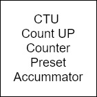
10) The accumulated value and control bits are reset when the appropriate RES instruction is enabled. The function block of a count upCTTU is shown
Count down (CTD)
1) The CTU is a retentive output instruction that count false to true transmissions.
2) When the rung condition for a CTD instruction has made a false-to-true transmission the accumulated value is decremented by 1 counter instruction is evaluated between their transitions.
3) The accumulated counts are retained when the rung condition again becomes false.
4) The accumulated account is retained until cleared by a reset (RES) instruction that has the same address as the counter reset.
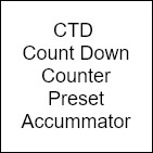
Then the reset instruction is used for a counter, the ACC value is 0 and ON bit is reset, CU bit is reset and CD bit is reset.
Reference Books:
[R1] Gordan Clark, Deem Reynders, “Practical Modern SCADA Protocols”, ELSEVIER
[R2] Batten G. L., “Programmable Controllers”, McGraw Hill Inc., Second Edition
[R3] Bennett Stuart, “Real Time Computer Control”, Prentice Hall, 1988
[R4] Krishna Kant, “Computer Based Industrial Control”, PHI
[R5] P. K. Srivstava, “Programmable Logic Controllers with Applications”, BPB
Publications