Unit– V
SCADA System
1) The scope of SCADA has evolved from its beginning in the 1960s.
2) The advent of low-costminicomputers such as the digital equipment corporation PDP-8 and PDP-11 MID computer control of process and manufacturing operation feasible.
3) Programmable Logic controllers (PLC) progressed simultaneously.
4) These latter devices implemented traditional relay ladder logic to control industrial process.
5) PLC appealed to traditional control engineers who were accustomed to programming relay logic and who did not want to learn programming language and operating systems.
6) When micro computers were developed, they were programmed and packed toemulate PLC in function, programming, and operations.
7) In fact, competition developed between the two approaches and continuous to this day.
8) Initially control system work confined to a particular plant.
9) The associated control devices were local to the plant and not connected to an external network.
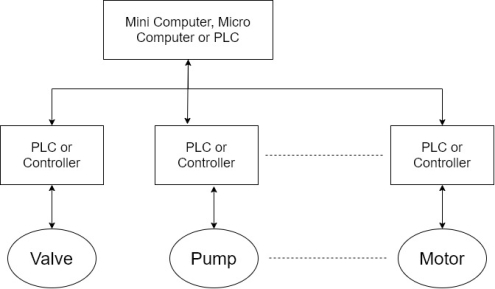
10) The early control system consisted of a central microcomputer or PLC, that communicated with local controllers that interfaced with motors, pumps, valves, switches, sensors and soon. Shown in figure.
11) This architecture is sometimes referred to as a distributed control system.
12) Such system is generally confined to locations close to each other normally use a high-speed local network and usually involved closed loop control.
13) As a necessary requirement for the operation of these systems, companies and vendors developed there on communication protocol meaning of which were proprietary.
14) As the technical capabilities of computer operating system and network improves, organizational management post for increase knowledge of the real-time status of remote plant operations.
15) Also, in organizations with a number of geographical separated operations, remote data acquisition control and maintenance became increasingly attractive from management and cost stand points.
16) Their capability is known collectively as supervisory control and data acquisition or SCADA.
1) SCADA is the technology that enables a user to collect data from one or more distant facilities. -Stuart A. Boyer, Published by ISA [ISA- The Instrumental system and Automation Society, third edition]
2) A System operating with coded signal over communication channels so as to provide control of remote terminal unit equipment. –IEEE Standards C.37.1- 1994
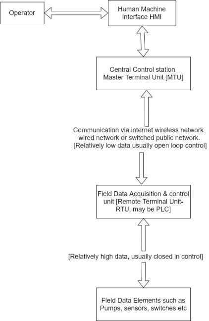
1) Specific terminology is associated with the component of SCADA systems. The SCADA elements are defined as follows
2) Operator :- Human operator who monitor the SCADA system and perform supervisory control function for the remote plant operations.
3) Human machine interface (HMI) :- presents data to the operator and provides for control input in a variety of formats including graphics schematic, windows, pull down menus, touch screen and so on.
4) Master terminal unit (HMU):- Equivalent to a master unit in a master slave architecture. The MTU presents data to the operator through the HMU gathers data from the distant sight and transmits control signal to the remote side. The transmission rate of data between MTU and the remote site is relatively 10 W ant control method is usually open loop because of possible time delays or data flow instructions.
5) Communication means :- Communication method between the MTU and remote controllers communication can be through the internal wireless or wired network or the switch .
6) Remote Terminal Unit RTU):- Functions as a slave in the master/slave architecture, cents control signal to the device under control acquired data from these devices and transmit the data to the MTU. An RTU maybe a PLC. The data rate between the RTU and controlled devices is relative Lehigh and control method is usually closed loop.
7) A SCADA architecture comprises two levels, a master or client level at the supervisory control Centre and a slave or data server level that interacts with the processes under control. In addition to the hardware, the software components of the SCADA architecture are important. Here are some of the typical SCADA software components.
SCADA Master/Client
1) Human machine interface
2) Alarm handling
3) Event and log monitoring
4) Special applications
5) Active X or JAVA controls
SCADA slave or data server
1) Real time system manager
2) Data processing applications
3) Report generator
4) Alarm handling
5) Drivers and interfaces to control components
6) Spreadsheet
7) Data logging
8) Achieving
9) Chatting and trending
Communication Architectures:-
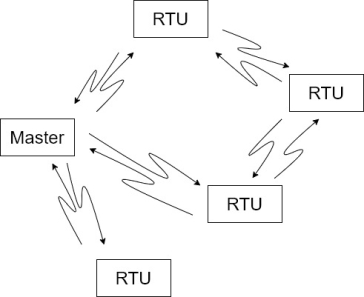
There are three main physical communication architecture that can be combined in one communication system.
1.Point to points architecture:-This is the simplest configuration where data is exchanged between two stations only one station can be set up as the master and as the slave. It is possible for both station to communicate in full duplex mode [transmitting and receiving on two separate frequencies] or half duplex with only one frequency.

2.Multipoint architecture:- {Multiple stations}
In this configuration there is generally one master and multiple slaves. Normally data is passed between the master and each of the slaves. If two sleeves need to transfer data between each other they would do so through the master that acts as a moderator.
Alternatively, it is possible for all the stations to act in a peer-to-peer relationship. This is a more complex arrangement requiring sophisticated protocols to have collision between two different stations wanting to transmit at the same time.
3.Relay station architecture:-
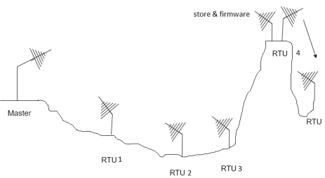
There are two possibilities here namely store-and-forward to talk through repeaters.
Store and forward relay operation can a component of the other approaches discussed above. This takes place near station retransmits message to another station that is out of the range of the master station. This intermediate station is often called a store and forward relay station.
There is no simultaneous transmission of the message by the store and forward release station. It first receives and store the message, then transmit it on the same frequency as the one on which it was received from the master station. This approach is slower than a talk to repeater as each message has to be sent twice. The advantages are considerable savings in most heights and costs.
Basic standards: RS- 232 and RS- 485
These standards were designed primarily to transport digital data from one point to another. The RS:232 standards was initially designed to connect digital computer equipment to a modem where the data would then be converted into an analogue form suitable for transmission over greater distances. RS-485 has the ability to transfer digital data over distance of over 1200 m.
RS-232:-
The RS-232 interface standard for serial data communication defines the interface between Data Terminal Equipment(DTE) and data communication equipment (DCE) employing serial binary data interchange.
The RS-232 standard consists of three major parts which define 1) The electrical signal characteristics search the voltage levels and grounding characteristics of the intelligent signals are associated circuitry.
1) the interface mechanical characteristics of the mechanical interface between DTE and DCE.
2) The functional description of the interface circuit such as the function off the data, timing and control signals used at the interface between DTE and DCE.
The RS-232 interface standard is designed for the connection of two devices.
i) DTE:- Data terminal equipment e.g. (computer). DTE device communicate with a device and transmits data on pin 2 and receive data on pin 3 on a 25 pin D-type connector.
Ii) DCE:-
Data communication equipment, now also so-called data circuit terminating equipment in RS-232 (e.g. Computer or modem). DCE device transmits between the DTE and a physical data communication link (e.g. Telephone system). It transmits data on pin 3 and receive data on pin 2 on a 25 pin D- type connector.
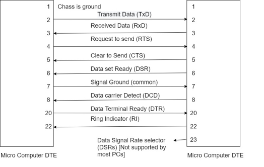
The connection between DTE and DCE.
Functional description of the interchange circuits
Pin 1:- Protective Ground (Shield)
A connection is seldom made between the protective ground pins at each end. Their purpose is to prevent hazardous voltage ensuring that the DTE and DCE chassis are at the same potential at both ends. There is, however, a danger that a path could be established for circuitry earth currents. Consequently, the cable shield is usually connected at one end only.
Pin 2:- Transmitted data (T×D)
This line carries serial data from pin 2 on the DTE to pin 2 on the DCE. Deadline is held at MARK (OT a negative) during periods of line idle.
Pin 3:- Received data (R×D)
This line carries serial data from pin 3 on the DCE 2 din 3 on the DTE.
Pin 4:- Request to send (RTS)
See clear to send
Pin 5:- Clear to send (CT5)
When a half-duplex modem is receiving DTE keeps RTS inhibited. When it becomes, Date’s turn to transmit, it advises the modem by asserting RTS pin when the modem exerts the CTS it in forms the DTE that is new safe to send data.
Pin 6:- Data Set Ready (DSR)
This is also called DCE ready. In the answer mode, the answer tone and the DSR are asserted two seconds after the telephone goes of book.
Pin 7:- Signal Ground (Common)
This is the common return line for the data transmit and receive signals. Type test the connection of pin 7 to pin 7 between the two ends is always made.
Pin 8:- Data Carrier Detect (DCD)
This is also called the received line signal detector. Pins is exerted by the modem when it receives a remote carrier and remains asserted for the duration of the link.
Pin 20:- DTE ready (or data terminal ready)
DTE ready enables but does not cause the modem to switch on to the line. In originated mod, DTE Reddy must be asserted in order to auto dial. In answer mode, DTE ready must be asserted to auto answer.
Pin 22:- Ring indicator
This pin is asserted during a ring online.
Pin 23:- Data signal rate selector (DSRS)
When two data rates are possible the high is selected by asserted pin 23.
RS -485:-
RS – 485 permits multidrop network connection on the wire and provides for reliable serial data.
Communication for
- Distance of up to 1200 m
- Data rates UP to 10 Mbps
Upto 32-line drivers permitted on the same line and up to 32-line receivers are permitted on the same line.
The line voltage range is between -1.5 to -6 V for logic 1 and +1.5 to +6V for logic 0. As with RS- 422, the line driver for the RS- 485 interphase produces a 5-volt differential voltage on two wires. For a half-duplex system, only three wires are required. The additional wire is to provide a common reference voltage for devices on the system.
The major enhancement of RS - 485 is that online driver can operate in three states (cold tri state operation) namely logic '0’ , logic '1’ and high impedance, where it grows virtually no current and appears not to be present on the line. The latter state is known as the disabled state and can be initiated by a signal on a control pin on the line driver integrated circuit. This allows multi drop operation, where up to 32 transmitters can be connected on the same line all through only one can be active at any one time. Each terminal in a multi drop system must therefore be allocated unique address to avoid any conflict with other devices on the system. RS – 485 includes current limiting in cases where contention occurs.
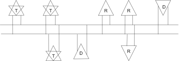
T=Transceiver
D= Driver
R= Receiver
The RS –485 multipoint interface standard.
1) The typical SCADA system that incorporate standard hardware and software platforms such as PC’S and windows.
2) The SCADA system is linked with two external networks, corporate IT operations and remote possibility insecure access points such as modems.
3) Because standard hardware and software used the equipment is vulnerable to the same attacks that historical e have been mounted against PC’s and windows.
4) A successful unauthorized penetration of a SCADA system could result in an intruder taking control of a master or slave unit, disrupting critical processed, falsifying data and even initiating actions that could result in the loss of human life and destruction of the plant under control.
5) A good description of the desirable properties of a SCADA system is given in the North American Electric Reliability Council (NERC) definition of SCADA reliability objectives.
6) Even through the definition addresses the electrical utility industry, the properties can be extrapolated to do all components of nation critical infrastructure.
- Adequacy:-
The capacity to meet system demand within major component rating in the presence of scheduled and unscheduled outage of generation and transmission components and facilities.
- Security :-
A system capability to do with stand system disturbances arising from faults and unscheduled removal of bulk power elements without further loss of facilities and cascading outages.
1) The computer can record and store a very large amount of data.
2) The data can be displayed in anyways the user requires.
3) Thousands of sensors over a wide area can be connected to the system.
4) The operator can incorporate real data simulations into the system.
5) Many types of data can be collected from the RTU's.
6) The data can be viewed from anywhere not just on site.
7) Minimal wiring is needed.
8) The operator can see down to the sensor level,
9) The data received from the device can include information such as serial numbers, model numbers.
10) All devices plug and play, so instant and replacement are easy.
11) Small devices mean less physical space for the data acquisition system.
1) The system is more complicated than the sensor to panel type.
2) Different operating skins are required such as system analysis and programmer.
3) With thousands of sensors there are still a lot of wires to deal with
4) The operator can see only as far as PLC.
5) Nature sophisticated system requires better trained employees.
6) Sensor prices are higher.
7) The IED's relay more on the communication system.
First generation – Monolithic
Second generation – Distributed
Third generation – Network
1. Monolithic SCADA systems
i) The wide area network (WAN) that was implemented to communicate with remote terminal units (RTU) what designed with a single purpose in mind that of communicating with RTU's in the field and nothing else. In addition, WAN protocols in use today were largely unknown at the time.
Ii) The communication protocols in use on SCADA network were developed by vendors of our RTU equipment and were often proprietary.
Iii) In addition, these protocols were generally very 'lean' , supporting virtually no functionality beyond that required scanning and controlling prints within the remote device.
Iv) Also, it was generally not visible to intermingle other types of data traffic with RTU communications on the network.
v) Connectivity to the SCADA master station itself was very limited by the system vendor.
Vi) Connections to the master typical work done at the bus level via a proprietary adaptor or controller plugged into a CPU backplane.
Vi) Redundancy India's first-generation systems was accomplished by the use of two identically equipped mainframe systems. A primary and a backup connected at the bus level.
Viii) The standby systems primary function was to monitor the primary and take over in the event of a detected failure.
IX) This type of standby operation means that little or no processing was done on the standby system.
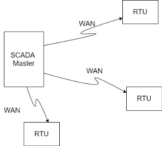
2. Distributed SCADA Systems:-
i) The next generation of SCADA systems took advantage of development and improvements in system miniaturization and Local Area Networking (LAN)technology to distribute the processing across multiple systems.
Ii) Multiple stations, each with the specific function were connected to a LAN and shared information with each other in real time.
Iii) These stations were typically of the minicomputer class, smaller and less expensive than their first-generation processor.
Iv) Some of these distributed stations served as communications processes, primary communicating field devices such as RTU's.
v) Some soft as operator interfaces, providing the Human Machine Interface (HMI) for system operators.
Vi) Still others served as calculation processes or database servers.
Vii) The distribution of individual SCADA system functions across multiple systems providing more processing power for the system as a whole then would have been available in a single processor.
Viii) The networks that connected this individual systems were generally based on LAN protocols and were not capable of reaching beyond the limits of the local environment.
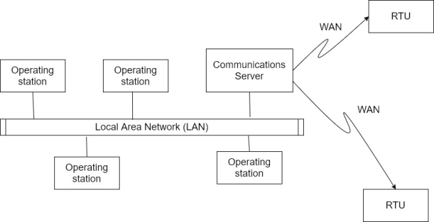
Ix) Distribution of system functionality across network connected system software not only to increase processing power but also to improve the redundancy and reliability of the system as a whole.
x) Rather than the simple primary/standby failover scheme that was utilized in many first generation, the distributed architecture often kept all stations on the LAN in an online state all of the time.
Xi)For example, if an HMI station were to fail, another HMI station could be used to operate the system without waiting for failover from the primary system to the secondary.
Xii) The WAN used to communicate with devices in the field world largely unchanged by the development of LAN connectivity between local stations at the SCADA master.
Xiii) These external communications network was still limited to RTU protocols and were not available for other types of network traffic.
3. Networked SCADA systems:-
i) The current generation of SCADA master station architecture is closely related to that of the second generation with the primary difference being that of an open system architecture rather than a vendor controlled proprietary environment.
Ii) There are still multiple network systems sharing master station functions.
Iii) The major improvements in the third generation is that of opening the system architecture, utilizing open standards and protocols, and making it possible to distribute SCADA functionality across a WAN and not just LAN.
Iv) Open standard eliminatesa number of the limitations of previous generations of SCADA system.
v) The utilization of off – the – shelf systems make it easier for the user to connect third-party peripheral devices (such as monitors, printers, disc drives, tape drives etc.) To the system and/or network.
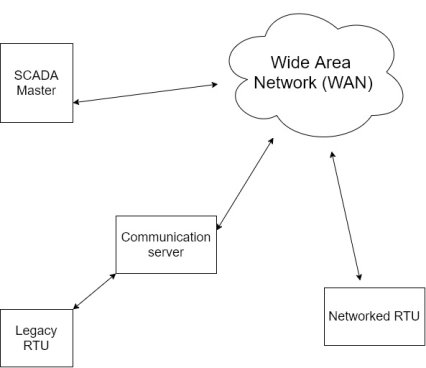
Vi) The major improvement in third generation SCADA system comes from the use of WAN protocols such as their internet protocol (IP) for communication between the master station and communication equipment.
Vii) This allows the portion of the master station that is responsible for communications with field devices to be separated from the master station “proper” across WAN.
Intelligent Electronic Device (IED) :-
1) Any electronic device that processes some kind of local intelligent can be called as IED.
2) In the protection and power system automation industry, the term really came into existence to describe a device that has versatile electrical protection function, advanced local control intelligence, monitoring abilities and the capability of extensive complications directly to a SCADA system.
3) The functions of a typical IED may be more advanced than others and some may emphasize certain functional aspects over others, but these main functionalities should be incorporated to a greater or lesser degree.
I. Protection:-
The protection functions of the IED evolved from the basic overcurrent and earth fault protection functions of the feeder protection relay. This is due to fact that is feeder protection relay is used on almost all distribution switch board and the fact that more demanding protection function are not required enable the relay microprocessor to be used for control functions.
The IED is also meant to be as versatile as passive and is not intended to be a specialized protection relay, for example generator protection. This also makes the IED affordable.
The following is a guideline of protection related functions that may be expected from the most advanced IED's.
1) Non-directional three phase overcurrent [low set, high set, and instantaneous functions blocks, with hundred set selectable as long time, normal, very extremely inverse for definite time]
2) Non directional Earth fault protection [low set, high set, and instantaneous function blocks].
3) Directional three phase overcurrent [low set, set, and instantaneous functions blocks, with low set selectable as long time, normal, very old extremely inverse a definite time]
4) Directional Earth fault protection [low set, high set, and instantaneous function blocks].
5) Phase discontinuity protection
6) Three phase overvoltage protection
7) Residual overvoltage protection
8) Three phase under voltage protection
9) Three phase T/F in rush/ motor start up current elector.
10) Auto re closure function
11) Under frequency protection
12) Over frequency protection
13) Three phase thermal overload protection
II. Control :
Control functions include local and remote control and are fully programmable
1) Local and remote control of up to twelve switching objects [open close command for C.B isolator etc.]
2) Control sequencing
3) Bay level interlocking of the controlled device
4) Status information
5) Information of alarm channels
6) HMI panel on device
III. Monitoring:-
Monitoring includes the following functions
1) C.B. Condition monitoring, including operation time counter, electric wire, breaker travel time, scheduled maintenance.
2) Trip circuit supervision
3) Internal self-supervision
4) Gas density monitoring [for Sf6 switchgear]
5) Event recording
6)Other monitoring functions, like auxiliary power relay temperature etc.
IV. Metering:-
Meeting functions include
1) Three phase current
2) Neutral current
3) Three phase voltages
4) Residential voltage
5) Frequency
6) Active power
7) Reactive power
8) Power factor
9) Energy
10) Harmonics
V. Communications
1) IED's are able to communicate directly to a SCADA system, i.e. upper level communications.
2) different manufacturer uses different communication protocols, although the most popular are DNP3 and Modbus.
3) In to upper level communications also have a serial port or optical interface to communicate directly to a substation PC or laptop for configuration and data downloading purpose upper level communications also have a serial port or optical interface to communicate directly to a substation PC or laptop for configuration and data downloading purpose.
SCADA system security issues overview:-
1) For reason of efficiency, maintenance and economics data acquisition and control platforms have migrated from isolated in plant network using proprietary hardware and software to PC based systems using standard software, network protocol and the internet.
2) The downside of this transition has been to expose SCADA system to the same vulnerability and threats that plague windows best PC and their associated networks.
3) Some typical attacks that might be against SCADA system that employee standard hardware and software are listed below
- Malicious code such as viruses and worms
- Unauthorized disclosure of critical data
- Unauthorized modification and manipulation of critical data
- Denial access to audit logs and modification of audit logs.
4) Most SCADA systems, particularly the local PLCs or controllers, have to operate in real time or near real time environment.
5) Thus, they cannot afford delays that might be caused by information security software and that interfere with critical control decision affecting personal safety product quality and cost.
6) Also, plant SCADA systems components do not usually have excess memory capacity that can accommodate relative Li large programs associated with security monitoring activities.
7) In summary, conventional IT systems are concerned with providing for internal and external connectivity, productivity, extensive security mechanism for defecation and authorization and the three major information security principle of confidentiality, reliability, and integrity.
8) Conversely, SCADA system emphasize reliability real time response, tolerance of emergency situations where passwords might be incorrectly entered, personal safety product quality and plant safety.
This automation includes feeder voltage or VAR control and feeder automatic switching. Feeder voltage control performs voltage regulation and capacitor placement operations while feeder switching deals with remote switching of various feeders, detection of faults, identifying fault location, isolating operation and restoration of service.
In this system, SCADA architecture continuously checks the faults and their location by using wireless fault detector units deployed at various feeding stations. In addition, it facilitates the remote circuit switching and historical data collection of feeder parameters and their status. The figure below illustrates feeder automation using SCADA.
In the above typical SCADA network, different feeders (underground as well as overhead networks) are automated with modular and integrated devices in order to decrease the number and duration of outages. Underground and overhead fault detection devices provide accurate information about transient and permanent faults so that at the remote side preventive and corrective measures can be performed in order to reduce the fault repeatability.
Ring main units and Remote Control Units (RTUs) of underground and overhead network responsible for maintenance and operational duties such as remote load switching, capacitor bank insertion and voltage regulation. The entire network is connected with a communication medium in order to facilitate remote energy management at the central monitoring station.
The important features of SCADA are the following:
1.AlarmHandling
2.Trend,Curves,Patterns
3.Data,AccessandRetrieval
4. Computer Networking and Processing
Alarms Handling
Alarm handling consists essentially of time stamped alarms to 1 millisecond precision. Single network acknowledgment and control of alarms with Sharing and Displaying of Alarms to all clients in chronological order.
It performs Dynamic allocation of alarm pages and keeps track of deviation and rate of change monitoring for analog alarms. It has the option of Historical alarm and event logging. It is capable of performing On-line alarm disable and threshold modification with the option of preparing Event-triggered alarms and Alarm-triggered reports
Trends
Trend curves and patterns consists of Trend zooming and display of data. It performs Export and Archiving of historical trend data with Event based trends for Short and long term trend display. It has the option of On-line change of time-base and retrieval of archived historical trend data.
Real Time access and archiving and database Management.
Real time access and data retrieval consists of Direct, real-time access to data by any network user as well as Third-party access to real-time data. It has Network compatibility for read, write and exec to all I/O device points. Support for Direct SQL commands or high level reporting
Computer Networking and processing
Computer Networking and processing aspect of supports all compatible networks and protocols. It has Centralized alarm, trend and report processing – data available from anywhere in the network and Dual networks for full LAN redundancy. Open architecture design with Real-time multitasking are important features with Client/server fully supported with Distributed project updates and Concurrent support of multiple display nodes.
Benefits of SCADA System
Increased life of the equipment being used by through immediate knowledge of system performance.
Reduced labor costs required for troubleshooting or service.
Increased compliance with regulatory agencies through automated report generating.
No requirement of large capital investment.
Many automation companies are using the SCADA to provide access to real-time data display, alarming, trending, and reporting from remote equipment.
It gives the flexibility to choose equipment and systems based on performance rather than compatibility with installed base.
SCADA are used to collect, monitor, maintenance and control industrial processes, Building management systems, water systems, and also other processes
Major functions of SCADA system are:
- Supervision or monitoring
- Controlling.
- Data acquisition
- Communication with PLC.
- Data presentation.
In substation automation system, SCADA performs the operations like bus voltage control, bus load balancing, circulating current control, overload control, transformer fault protection, bus fault protection, etc.
SCADA system continuously monitors the status of various equipments in substation and accordingly sends control signals to the remote control equipments. Also, it collects the historical data of the substation and generates the alarms in the event of electrical accidents or faults.
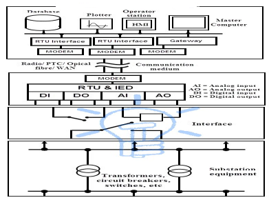
The above figure shows the typical SCADA based substation control system. Various input/output (I/O) modules connected to the substation equipment gathers the field parameters data, including status of switches, circuit breakers, transformers, capacitors and batteries, voltage and current magnitudes, etc. RTUs collect I/O data and transfers to remote master unit via network interface modules.
The central control or master unit receives and logs the information, displays on HMI and generate the control actions based on received data. This central controller also responsible for generating trend analysis, centralized alarming, and reporting.
The data historian, workstations, master terminal unit and communications servers are connected by LAN at the control center. A Wide Area Network (WAN) connection with standard protocol communication is used to transfer the information between field sites and central controller.
Thus, by implementing SCADA for substation control eventually improves the reliability of the network and minimizes the downtime with high speed transfer of measurements and control commands.
An energy management system (EMS) is a system of computer-aided tools used by operators of electric utility grids to monitor, control, and optimize the performance of the generation or transmission system. Also, it can be used in small scale systems like micro grids.
The computer technology is also referred to as SCADA/EMS or EMS/SCADA. In these respects, the terminology EMS then excludes the monitoring and control functions, but more specifically refers to the collective suite of power network applications and to the generation control and scheduling applications.
Manufacturers of EMS also commonly supply a corresponding dispatcher training simulator (DTS). This related technology makes use of components of SCADA and EMS as a training tool for control center operators.
Operating systems
Up to the early 1990 it was common to find EMS systems being delivered based on proprietary hardware and operating systems. Back then EMS suppliers such as Harris Controls (now GE), Hitachi, Cebyc, Control Data Corporation, Siemens and Toshiba manufactured their own proprietary hardware. EMS suppliers that did not manufacture their own hardware often relied on products developed by Digital Equipment, Gould Electronics and MODCOMP. The VAX 11/780 from Digital Equipment was a popular choice amongst some EMS suppliers. EMS systems now rely on a model based approach. Traditional planning models and EMS models were always independently maintained and seldom in synchronism with each other. Using EMS software allows planners and operators to share a common model reducing the mismatch between the two and cutting model maintenance by half. Having a common user interface also allows for easier transition of information from planning to operations.
As proprietary systems became uneconomical, EMS suppliers began to deliver solutions based on industry standard hardware platforms such as those from Digital Equipment (later Compaq (later HP)), IBM and Sun. The common operating system then was either DEC OpenVMS or Unix. By 2004, various EMS suppliers including Alston, ABB and OSI had begun to offer Windows based solutions. By 2006 customers had a choice of UNIX, Linux or Windows-based systems. Some suppliers including ETAP, NARI, PSI-CNI and Siemens continue to offer UNIX-based solutions. It is now common for suppliers to integrate UNIX-based solutions on either the Sun Solaris or IBM platform. Newer EMS systems based on blade servers occupy a fraction of the space previously required. For instance, a blade rack of 20 servers occupy much the same space as that previously occupied by a single MicroVAX server.
The Five Operating States of an Electric Power System
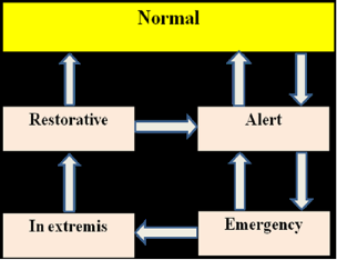
In the wake of the 1965 Northeast blackout in the US, the electric power system community has embarked in a journey of fruitful research and developments aimed at modernizing the monitoring, protection, and control of the electric power generation, transmission and distribution systems. This endeavor has resulted in many methodological and technological advancements, which include the following: (i) the provision of the control centers with mainframes and, later on, distributed computers; (ii) the initiation of a theoretical framework along with an ensemble of computer-aided functions to partially automatize the operation of the transmission system; and (iii) the development of fast algorithms based on sparse matrix techniques for modeling the steady-state and the dynamic operating conditions of the system. The theoretical framework was set up by Dy Liacco and then Fink and Carlsen with the definitions of five operating states of a power system which, as depicted in Fig., consist of the normal, alert, emergency, in extremis, and restorative state. These definitions are motivated by the characteristics of the dynamics of a power system, which are governed by a set of nonlinear differential equations and two nonlinear algebraic equations. The latter consist of two ensembles of equality and inequality constraints. It is worth recalling these definitions:
Normal state: It is a state characterized by the satisfaction of all the equality and inequality constraints and by a sufficient level of stability margins in transmission and generation so that the system can withstand a single contingency, be it a loss of a transmission line, a transformer, or a generator. In that case the system state is deemed to be secure; consequently, no action is taken.
Alert state: It is a state typified by the satisfaction of all the equality and inequality constraints and by an insufficient level of stability margins, which is an indication that the system is dangerously vulnerable to failures. This means that in the event of a contingency, at least one inequality constraint will be violated, for example due to the overload of a transmission line or a transformer. To bring the system to a normal state, preventive actions have to be taken, typically by increasing the structural redundancy in the transmission system.
Emergency state: It is a state where all the equality constraints are satisfied and at least one inequality constraint is violated, indicating that the system is experiencing overloads. Obviously, the system calls for the immediate implementation of corrective actions to remove the overloads, prevent the damage of equipment, and mitigate the risk of cascading failure that may result in a blackout. These actions consist of load shedding, transmission line trippings, transformer outages, or generating unit disconnections.
In extremis state: It is characterized by the violation of both equality and inequality constraints that stem from the chain of actions taken at a previous emergency state while the transmission network remains interconnected. At this stage, heroic actions are implemented to either reconnect the disconnected load and generation if this is at all possible or to perform additional outages to protect the overloaded equipment, which may result in the breakup of the network.
Restorative state: It is a state where the equality and inequality constraints are violated while the system is breaking up into pieces, resulting in the formation of islands that may be energized or not. Here, restorative actions need to be implemented to bring the system to a normal or alert state.
SCADA system in the critical infrastructure:-
1) Petroleum refineries are extremely important elements in a nation’s critical infrastructure.
2) Goods and services depend on transportation by plains, trucks, cars, trains, and boats one on the myriad of engines running on petroleum-based fuels.
3) To achieve economic viability, petroleum refineries have to operate at high volumes in a continuous process.
4) Thus, they are built to handle large capacities and run on 24 hours, seven days per week basis.
5) For kids of receiving the row crude oil and transporting the refinery products, most refineries are located near ports on river.
6) In most instances, put functions and security are dependent, directly, or indirectly on the proper operation of SCADA systems.
The basic Refinery Process
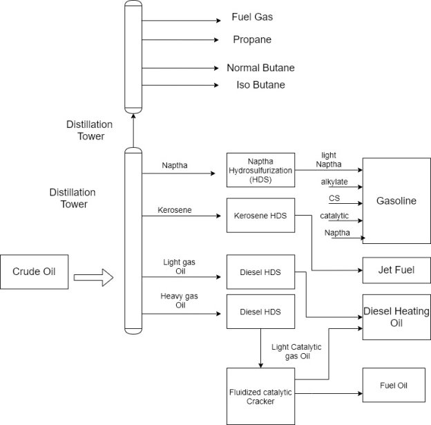
1) The principal function of a refinery is to distil and perform various chemical reactions on the crude oil input.
2) This operations required temperatures on the order of 500-1000 degrees Fahrenheit and pressure ranging from 150 pounds per square inch (PSI) to 3500 PSI.
3) As part of the refining process, combustible and toxic substance are produced.
4) In addition to the general fuel products hydrogen is used and the toxic compounds hydrogen sulfide and ammonia are generated.
5) In a refinery distillation column, the component hydrocarbons can be separated because they have different boiling points that reach from approximately 50-degree Fahrenheit to 1400 degrees Fahrenheit.
6) This process is called fractionation which is the result of adding heat to the bottom of the distillation tower and establishing a temperature profile through the tower from bottom to top.
7) The proper temperature gradient is maintained by removing heat from the top of the tower.
8) The lower boiling point hydrocarbons migrate to the top of the tower as vapor and the higher boiling point substances are found at the bottom of the tower in the liquid state.
9) Hydrocarbons in the intermediate boiling point range are extracted from the side of the tower.
10) The substances usually contain sulfur in amount that exceeds these tolerable in the finished product add that can contaminate catalyst used in the refining process.
11) The sulfur is removed through hydrocarbon which mixes hydrogen gas with the hydrocarbon stream at high temperature and uses a catalyst to support the desired chemical reaction.
12) This operation is known as hydra sulfurization or HDS.
13) A product of this reaction is the toxic gas hydrogen sulfide hich results from hydrogen atoms combining with Sulphur atoms.
14) A similar process use hydrogen to remove unwanted nitrogen from hydrocarbons streams. This process is known as hydrodenitrogenation (HDN) and yields ammonia,  a product of the reaction.
15) It is clear that petroleum refineries must be kept under strict control in all phases of hydrocarbon processing or serious damage to human life property and eventually, the economy will result.
16) With refineries under SCADA controls they are by definition, connected to wide area networks and used protocols that are subject to threats and attacks that can seize for impaired control of critical refinery processed.
17) Result of successful SCADA system attacks might include exceeding temperature and floor, escape of toxic liquids and vapors, and contamination of catalysis.
18) These conditions can produce a variety of harmful events ranging from defective products to fires, explosion, incapacitation of the refinery, human injury or death and contamination of wide areas.
1) A conventional electric power generating facility produces electricity by harnessing the energy of falling water or by generating heat through the burning of fossil fuels point in this example, a fossil fuel plant is examined.
2) Figure provides a geographic overview of a fossil fuel electric plant and the subsequent part of the generated electricity to an end user.
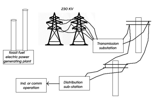
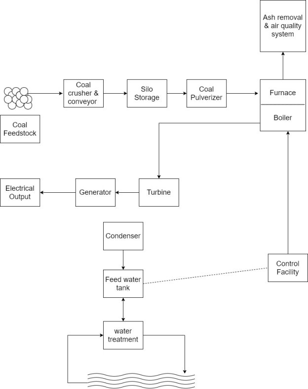
3) In a coal fired plant the coal is crushed, stored in silos, pulverized, and conveyed into a furnace.
4) The burning coal generates heat that impinges on a boiler and generates steam that is used to drive steam turbines.
5) The turbines, in turn, drive electricity generator that provide power to the transmission and distributed grid.
6) The steam is condensed and recirculate into the boiler to repeat the process.
7) There are many parameters and devices that have to be controlled for proper operation of the plant, including those related to emergencies.
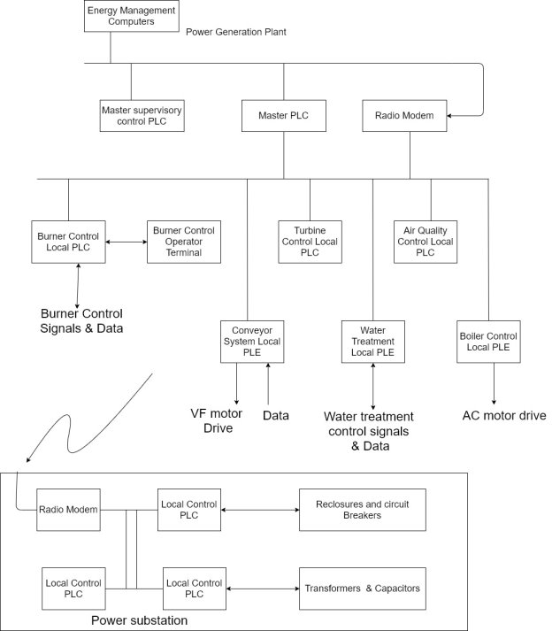
8) The main SCADA components are in the control room and at the substation.
9) The local control remote terminal units (RTU) are located throughout the plant are the needed control points.
10) The control components include the following
- Energy Management computers
- Master supervisory PLC
- Master supervisory hot backup
- Turbine control PLC
- Burner control PLC
- Air quality control PLC
- Water treatment PLC
- Boiler control PLC
- Conveyor system PLC
- Power substation local control PLC
The control stations and their interactions :-
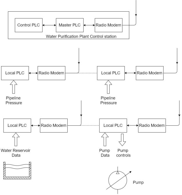
1) In a typical water purification operation, water is pumped from a reservoir or other water source to a water purification plant.
2) After purification, the water is pumped through a transmission system to the water consumers.
In designing a water purification system, the following items are considered
- Future expendability
- Terrain travelled by the water pipeline
- Control of system functions and performance
- Maintenance of water quality
3) For this type of operation, a SCADA system is applied to control and monitor the water purification process, pumping system, and pipeline pressures.
4) Because of the distance involved in same installation, radio models are used to communicate between the central supervisory station and the remote locations.
5) Possible attack scenarios on a water purification and transmission system include jamming or interference with radio communication links, disabling or interrupting the water purification process, inserting false pressure and pump data to disrupt transmission operation, and modifying water reservoir information.
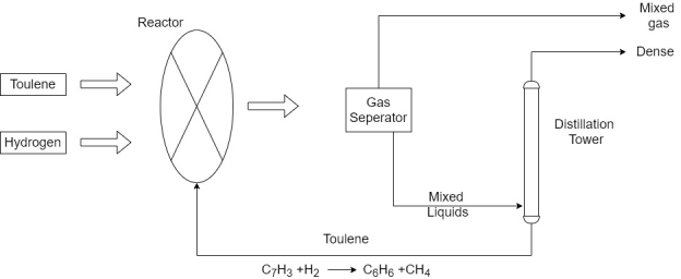
1) As an example, the production of benzene  reviewed to highlight the chemicals involved in the production process and the effects of interfering with SCADA system operations.
2) Benzene is Produced by three different methods. This methods are steam cracking, catalytic reforming, and toluene hydrode alkylation.
3) In the toluene hydride alkylation process, hydrogen reacts with toluene over a catalyst bed with temperature between 500 and 600 degree Celsius and 40 – 60 atmospheres of pressure.
4) Chemical reaction:-

5) The major hazards involved with disruptions or hijacking of SCADA control of a benzene production facility are associated with handling and reaction of the constituent components and resulting products. These items include toluene hydrogen benzene and methane.
6) Toluene ( flammable in liquid and vapour form. It is a colourless liquid with a density greater than air.
7) Thus, it can spread over wide areas and cause great damage if ignited. It has a density less than water, so that it remains at the surface and again, can spread over large distances.
8) Toluene can accumulate a static charge when flowing or shaken, thus, increasing the possible chance of ignition.
9) When heated, toluene forms toxic gases, which can cause drowsiness, dizziness, nausea, and headache when inhaled.
9) Toluene stored in closed containers can explode when heated by an external source, such as fire.
10) Hydrogen is flammable and if released and combined with an oxidizer, can result in a fire and explosion.
11) When hydrogen is converted from a liquid to gas, it generates and overpressure that can rupture containers.
12) The overpressure from a hydrogen explosion and contact with a hydrogen fire can cause serious harm to personnel and equipment.
13) Methane  a product of the benzene process. It is a combustible, colorlessodorless gas with a density lighter than air at room temperature
14) Methane mixtures of approximately 10% in air can cause explosions, breathing methane causes asphyxiation when inhaled by displacing oxygen in the lungs.
15) Benzene can cause drowsiness, dizziness and even death when inhaled.
16) Benzene is classified by the U.S. Department of Health and Human services as a carcinogen exposure and can also affect the blood and immune system.
Reference Books:
[R1] Gordan Clark, Deem Reynders, “Practical Modern SCADA Protocols”, ELSEVIER
[R2] Batten G. L., “Programmable Controllers”, McGraw Hill Inc., Second Edition
[R3] Bennett Stuart, “Real Time Computer Control”, Prentice Hall, 1988
[R4] Krishna Kant, “Computer Based Industrial Control”, PHI
[R5] P. K. Srivstava, “Programmable Logic Controllers with Applications”, BPB
Publications