Unit-1
Power System Stability
The central concept in the maintenance of synchronism is stability. Stability is the tendency of the power system (and of the synchronous machines in particular) to continue to operate steadily in the intended mode. It is also a measure of the inherent ability of the system to recover from extraneous disturbances (such as faults, lightning, and changes of load), as well as from planned disturbances (such as switching operations).
Definition Power System Stability: Power system stability may be broadly defined as the property of a power system that enables it to remain in the state of operating equilibrium under normal operating conditions and to regain an acceptable state of equilibrium after being subjected to a disturbance.
Bulk transmission of electrical power by ac is possible only if the following
Two fundamental requirements are satisfied:
Major Synchronous machines must remain stable in synchronism.
Voltages must be kept near to their rated values.
Major Synchronous machines must remain stable in synchronism.
The major synchronous machines in a transmission system are the generators
And synchronous condensers.
The central concept in the maintenance of synchronism is stability. Stability is the tendency of the power system (and of the synchronous machines in particular) to continue to operate steadily in the intended mode. It is also a measure of the inherent ability of the system to recover from extraneous disturbances (such as faults, lightning, and changes of load), as well as from planned disturbances (such as switching operations).
Steady state Stability: One of the limits to the utilization of a transmission line is that for a given length of line the stability tends to become less as the transmitted power is increased. If the power could be gradually increased (with no extraneous disturbances), a level would be reached at which the system would suddenly become unstable. The synchronous machines at the two ends of the line would pull out of step, that is, lose synchronism. This level of power transmission is the steady-state stability limit, so called because it is the maximum steady power that can (in theory) be transmitted stably.
It is not practical to operate a transmission system too near to its steady-state stability limit; there must be a margin in the power transfer to allow for disturbances (such as load changes, faults, and switching operations). In determining an appropriate margin, the concepts of transient and dynamic stability are useful.
Dynamic stability: A transmission system is said to be dynamically stable if it recovers normal operation following a specified minor disturbance.
The degree of dynamic stability can be expressed in terms of the rate of damping of the transient components of voltages, currents, and the load angles of the synchronous machines.
Transient stability: Transient stability of power transmission systems is whether the system will recover normal operation following a major disturbance, such as a fault severe enough to trip a major circuit, or failure of a major item of plant, such as a generator, overhead line, or transformer.
A system has transient stability if it can recover normal operation following a specified major disturbance.
Voltages must be kept near to their rated values.
The second fundamental requirement in ac power transmission is the maintenance of correct voltage levels. Modern power systems are not very tolerant of abnormal voltages, even for short periods.
Undervoltage: which is generally associated with heavy loading and or a shortage of generation, causes degradation in the performance of loads, particularly induction motors. In heavily loaded systems, undervoltage may be an indication that the load is approaching the steady-state stability limit. Sudden under voltages can result from the connection of very large loads.
Overvoltage: is a dangerous condition because of the risk of flashover or the breakdown of insulation. Saturation of transformers subjected to overvoltage can produce high currents rich in harmonics, and in the presence of sufficient capacitance there is a risk of ferro-resonance as well as of harmonic resonances.
Major causes of over-voltages:
- The sudden reduction of load during certain parts of the daily load cycle causes a gradual voltage rise.
- Over-voltages of extreme rapidity and severity can be caused by line switching operations, faults, and lightning.
- In long distance transmission systems, the Ferranti effect (overvoltage at light load) would limit the power transfer and the transmission distance if no compensating measures were taken.
Kinetic Energy (KE) at rotor of synchronous machine is given by
 (1)
(1)
J = Rotor moment of inertia in Kg-m2
ωsm = Synchronous speed in rad(Mech)/s
ω= = Rotor Speed in rad (Elect)/s
P= Number of poles of machine
 (2)
(2)
 (3)
(3)
Where,
 (4)
(4)
= Moment of inertia in MJ-s/rad (Elect)
The inertia constant H should be such that
 (5)
(5)
Where,
G= Machine raring (Base) in MVA (3 Phase)
H=Inertia constant in MJ/MVA or MW-s/MVA
It follows,
 MJ-s/Degree (Elect) (6)
M is also called the inertia constant.
Taking G as base, the inertia constant in p.u. is
 s2/ Degree (Elect) (7)
Under normal operating conditions the relative position of rotor axis and the resultant magnetic field axis Is fixed stop the angle between the two is known as power angle or torque angle. During any disturbance, the rotor will decelerate or accelerate with respect to the synchronously rotating air gap MMF, and a relative motion begins. The equation describing this relative motion is known as the swing equation.
Figure 1 shows the torque, speed and flow of mechanical and electrical wers in a synchronous machine. It is assumed that the windage, friction and n-loss torque is negligible. The differential equation governing the rotor namics can then be written as
 Nm (8)
Where,
θm = angle in rad (mech)
Tm = turbine torque in Nm; it acquires a negative value for a motoring machine
Te = electromagnetic torque developed in Nm; it acquires negative value for a motoring machine

Figure 1. Flow of Mechanical and Electrical power in Synchronous Machine
While the rotor undergoes Dynamics of Synchronous Machine as per Eq. (8), the rotor speed changes by insignificant magnitude for the time period of interest (1s). Equation (8) can therefore be converted into its more convenient power form by assuming the rotor speed to remain constant at the synchronous speed (ωsm). Multiplying both sides of Eq. (8) by ωsm′ we can write
 (9)
(9)
Where
Pm = mechanical power input in MW
Pe = electrical power output in MW; stator copper loss is assumed negligible.
Rewriting Eq. (9)
 (10)
(10)
Where,

Or
 (11)
(11)
It is more convenient to measure the angular position of the rotor with respect to a synchronously rotating frame of reference.
Let,
δ=θe – ωst; (12)
Rotor angular displacement from synchronously rotating reference frame (called torque angle/power angle)
 (13)
(13)
Hence Eq. (11) can be written in terms of δ as
 (14)
(14)
With M as defined in Eq. (6), we can write
 (15)
(15)
Dividing throughout by G, the MVA rating of the machine,
 (16)
(16)
In pu of machine rating base.
Where,
 (17)
(17)
In pu of machine rating base.
This equation (16) & (17), is called the swing equation and it describes the rotor dynamics for a synchronous machine (generating/motoring). It is a second-order differential equation where the damping term (proportional to dδ/dt) is absent because of the assumption of a lossless machine and the fact that the torque of damper winding has been ignored. Damping helps to stabilize the system. Damping must of course be considered in a dynamic stability study. Since the electrical power Pe depends upon the sine of angle δ, the swing equation is a non-linear second-order differential equation.
Multimachine System:
In a multimachine system a common system base must be chosen.
Let,


Equation (17) can then be written as

 pu in system base (18)
Where,
 (19)
(19)
= System inertia constant in system Base
Machines Swinging Coherently:
Consider the swing equations of two machines on a common system base.
 (20)
(20)
 (21)
(21)
Since the machine rotors swing together (coherently or in unison)

Adding Equations (20) and (21)
 (22)
(22)
Where,

 (23)
(23)

The two machines swinging coherently are thus reduced to a single machine as in Eq. (22). The equivalent inertia in Eq. (23) can be written as
 (24)
(24)
The above results are easily extendable to any number of machines swinging coherently.
 1.4 Power Angle Curve:
Power Angle curve and power Angle equation
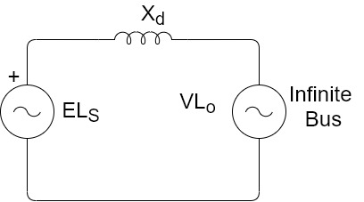
Figure A synchronous machine loaded at its terminal
Figure shows a synchronous machine having a direct axis synchronous reactance 
 Voltage behind synchronous reactance of generator
V=Terminal voltage of generator The complex power output of generator is


The real power output  of generator is


Thus, the real power output depends upon |E|,|V|,  and power angle
The reactive power Q is:-

Figure below shows the steady state Real power variation with Power angle for both generator and motor action for constant values of E, V and  . Thus, the curve is known as Power Angle curve.


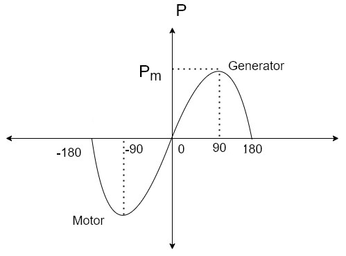
The maximum value of  for successful operation is 90. In actual practice
  is kept around 30.
The stability of single machine swing with respect to an infinite bus can be studied by use of equal area criterion. Figure shows power angle curve for an equivalent generator and representing a power exporting area connected to infinite bus.
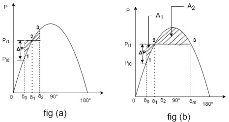
a) equal area criterion for a large sudden change in load.
b) Limiting case when 
Suppose under steady state condition at  large local load ∆P within the power exporting area is switched off. Assuming mechanical input remains same. The excess input is ∆P the rotor is accelerated leading to increase in
If 
Then the accelerating power  decreases from ∆P to zero.
By the time  goes to
  , the rotor absorbs kinetic energy, equals to the sheded area
  At point 2 the accelerating power is zero. But rotor acquires speed slightly greater than the synchronous speed, and
  continuous to increase beyond
As.  Becomes greater than.
 becomes negative and rotor retards. Rotor swings to continues to increase till load angle
  is and rotor attains the speed equal to synchronous speed
Neglecting all losses, the load angle.  Can be obtained from the condition that kinetic energy (KE)
KE during swing from 
=KE returned at its swing  .
.
This lead to conclusion that

This is referred as Equal area criterion.
The accelerating area  is given by


The decelerating area  is given by


For stability 
The equal area criterion can be Proved Mathematically as follows:

Multiplying above equation by  on both sides.

The load angle will have a maximum value when
 i.e. when
Thus, the rotor swings from. To maximum value. Which time the relative velocity is zero. The two shaded areas  must be equal and opposite sign this is shown in figure b
- Switching operation sudden loss of one of parallel line.
Figure a show inter connector consisting of two parallel lines connecting an equivalent generator (representing a power exporting area) equal area criterion can be used to study the transient stability of the system which one of the lines is switched out (simultaneously at both ends). To power angle diagrams are involved.
When both lines are operating power transfer is given by

In figure (b) when line 2 is switched off(out), the transfer reactance increases and the power transfer is given by

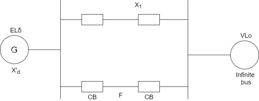
Figure(a) A machine connected to an infinite bus through an interconnector
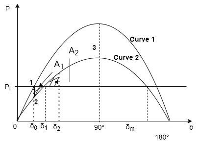
Figure equal area criterion as applied to the stability study of a switching operation.
The input to generator is  and therefore the initial conditions are represented by point 1 and the initial load angle is
 . When line 2 is switched off the operating point shifts to point 2 on curve 2
The power output is less than the power input and rotor accelerates, at  input and output are equal but angle continues to increase because rotor has acquired speed slightly greater than the synchronous speed. When
  deceleration of rotar starts swinging back. After few oscillations the load angle will stabilize at
  If the initial power transfer is increased (line
  shifts up words in figure b) a limit is reached beyond which the decelarating area
  cannot be equal to accelerating area
  . The maximum value which
  can attain without loss of system stability as
  And equals
  radians.
Sudden change in Mechanical input:

Figure above shows the transient model of a single machine connected to infinite bus bar. The electrical power transmitted is given by

Under steady operating condition

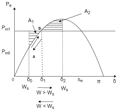
Let the mechanical input to the rotor be suddenly increased to  .the accelerating power
  causes the rotor speed to increase (w>
 )and so dose the rotor angle.
At angle  (
( )=0 at point b but the rotor angle continues
Increases as w>
Pa now become negative (decelerating)the rotor speed continuous to increase till at angle  ,
,
W= once again (state point a,b,c) the decelerating area
  (shaded). i.e

As the rotor speed is decelerating, the speed reduces below  , and rotor angle begins to reduce. the sate point now traverses the
  curve in opposite direction as indicated by arrows in figure The system oscillations about new steady state point b.
After oscillations die out due to inherent system damping, new style state arrives where 
From figure areas  and
and  are given by


As  is increased limiting condition is finally reached when
  equals to the area above
  line as shown in figure © below . Under this condition
  acquires the maximum value such that


Fig.(c) limited case of transient stability with mechanical input suddenly increased
Any further increase in  means area
  is less than
  ,excess kinetic energy causes the s to increase beyond point © and accelerating power with system consequently becoming unstable.
It can be seen from above fig that through the rotor may oscillate beyond 90=s the system will remain in stable state as long as equal area criterion is met. [ =90 for stability does not apply for transient stability].
3.EFFECT OF CLEARING TIME ON STABILITY
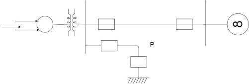
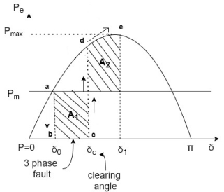
The system in fig (a) operating the mechanical input pm at steady state angle of  (
( ) at point in fig (b)
If a 3-phase fault occurs at point p (fig-a)  rotor state point drop to b, the acceleration begins also rotor angles moves b to c.
At time  and angle
  , fault is cleared by opening circuit breaker
  =clearing time.
 =clearing angle. After this system transmits
  . The rotor decelerates and curve moves along area
  (i.e d point towards e point) if
  is such that area
System is stable. And system settles down to point a in an oscillatory manner.
Relationship both 
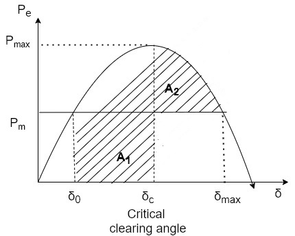
If fault clearing is delayed the angle  (fig-b) moves further to point
  max (fig-c) for clearing time is larger than this (Also the angle) then
  (i.e. system unstable).
The critical time =maximum allowable value of clearing time.
Critical angle clearing= Maximum allowable clearing angle
Relationship for critical angle  and critical time
  -Angle are in radians
From figure ©


For stable system 

Values from equation I and II putting in equation III

During this period fault persists, the swing equation is:-

For getting values of  and
and  integrating above equation twice:-


 is given by equation IV also
4) Sudden short circuit on one of parallel line
Case-a Short circuit at one end of line.

For Fig a assume a 3-phase fault F at one line 2
Before fault Power Angle curve is given by

Plotted in fig (b) below
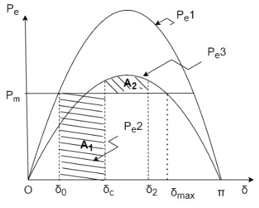
During fault 
The rotor accelerates, angle  increases the circuit breakers are opened at time
  (corresponding to
  ) clearing time, disconnecting the faulted line.
The power flow is now restored and reactance is now higher. (i.e.  instead of
  ).
).

Rotor now decelerates.
As area  depends upon clearing time
  (corresponding to clearing angle
  clearing time must be less than a value (critical clearing angle
  ) critical clearing angle is important as we can find in form curve not critical time.
System will be stable if  before
  reaches
  .
.
Case-b Short circuit away from line ends (Middle of a line)
[Refer fig a in Case-a]
If Fault occurs in middle of line, power flow changes and the system can be modelled as shown in fig (1) below
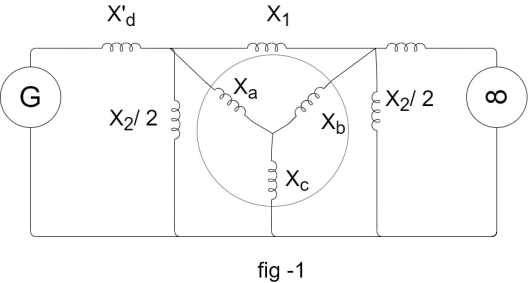
First converted to star and then Delta above Figure becomes
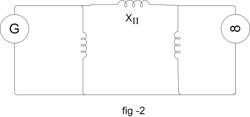
The power angle curve during fault is given by

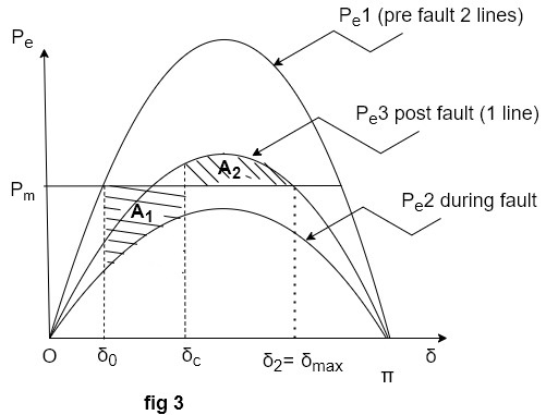
Area  corresponding to given clearing angle
  is less than case-
As the clearing angle is increased area  increases, and to find
 is increased till it has a value
  . This critical clearing angle maximum is shown in fig 3
Applying equal area criterion


Integrating->

Or 
Or

Critical clearing angle can be calculated from above equation for Case-b
Case-C Reclosure
[Refer Fig a in case -a]
If the circuit breaker on line -2 (on which fault has occurred ) is closed after clearing a transient fault. The power transfer becomes –

As the chances of stable operation improve, shown in figure below.
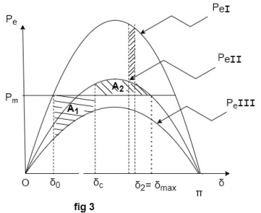
For critical clearing Angle


Where  =Time between clearing and reclosure)
Point-by-Point method for one machine tied to infinite bus-bar Consider a swing equation.

 or in pu system
  )
)
The solution  is obtained at descrete intervals of time with interval spread of
  uniform throughout.
- Accelerating power
 computed at the beginning of interval is assumed to remain constant from the middle of the next interval to middle of interval being considered.
 - The rotor velocity
 Assumed constant throughout any interval,
Fig: Point by point solution of swing equation

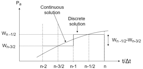
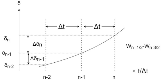
In figure The numbering on  axis belong to the end of intervals at the end of (n-1)th interval
The accelerating power is

Where  is previously calculated
Change in velocity from
 is
is

Change in  during (n-1)th interval is

During the nth interval

Subtracting equation IV from III and using equation II we get

We can now write

The process is repeated to obtain  . Normally time solution length is 0.5 seconds for discrete form can be reduced to get smooth curve. Continuous solution is obtained by drawing a smooth curve as shown in figure.
The occurrence or removal of fault or initiation of any switching event causes discontinuity in accelerating power  . In such case then the average values of
  before and after the discontinuity must be used.
Thus increment of angle occurrence during first interval after a fault is applied at t=0 is given by:-

Where  =Accelerating power immediately after occurrence of fault.
 =Before the fault
Maximum power can be transferred to load/sending end given by-

We can improve steady state stability by
Increasing inertia constant M of machine (But not employed due to economical reasons in practically and slowing down the response of speed governor loop.)
The maximum steady state power of system can be increased by rising the voltage profile of system.
Reducing Transfer reactance
Methods of improving Transient stability limit of system
1) Increase of system voltages by use of AVR (Automatic voltage Regulator):
When fault occurs, voltages at all buses are reduced. At generator terminal this is sensed by AVR, which acts to restore generator terminal voltage.
2) Use of High-speed Excitation systems: -
With the help of AVR within excitation system, modern exciter systems having solid state control quickly respond to bus voltage reduction within ½ to 1 and ½ (0.5 to 1.5) cycles.
3) Reducing Transfer reactance:
Reactance of a transmission line can be decreased by
I Reducing the conductor spacing
II Increasing conductor diameter
4) By using compensation for reactance of line by series compensation:
For more than 350Km length of line series capacitors can be used.
Switched Series Capacitors
Simultaneously decrease fluctuation of load voltages and raise transient stability limit.
Switching shunt capacitors on or switching shunt reactors off also raises system stability.
5) Use of high-speed reclosing
Breakers:
As most of the faults are transient in nature isolation of unhealthy lines rapidly improves system stability.
Single pole reclosing also improves the system stability to good extent.
Example 1.
A 50 Hz, four pole turbo generator rated 100 MVA, 11 kv has an inertia Constant of 8.0 MJ/ MVA.
(a) Find the stored energy in the rotor at synchronous speed.
(b) If the mechanical input is suddenly raised to 80 MW for an electrical load of 50 MW, find rotor acceleration, neglecting mechanical and electrical losses.
(c) If the acceleration calculated in part (b) is maintained for 10 cycles, find the change in torque angle and rotor speed in revolutions per minute at the end of this period.
Solution:
(a) Stored energy =GH=100*8=800MJ
(b) 


Or

© 10 cycles=0.2s
Change in 

Rotor speed at the end of 10 cycles


Example 1.
The system shown in figure, 3-phase static capacitive reactor of reactance 1pu per phase is connected through a switch at the motor busbar. Calculate the limit of steady state power with and without reactors switch closed. Re calculate the power limit with capacitive reactance placed by an inductive reactor of the same value.
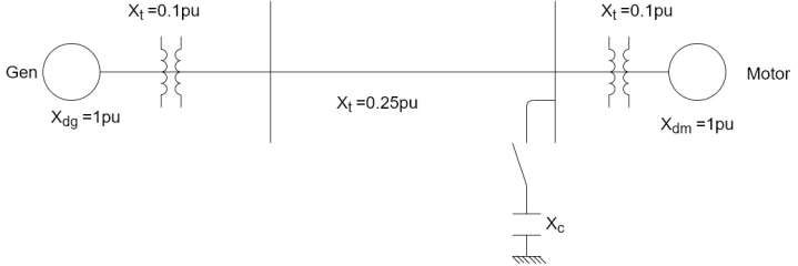
Assume the internal voltage of generator to be 1.2 pu and that of the motor to be 1.0 pu.
(1) Steady state power limit without reactor

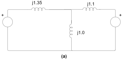
(2) Equivalent circuit with capacitive reactor is shown in Fig 12.11(a)

Converting Star to Delta the network of figure (a) in is to that of figure (b) where


Steady state power limit 
(3) With capacitive reactance replaced by inductive reactance, we get the equivalent circuit of Fig 12.12 Converting star to delta, we have the transfer reactance of


Steady state power limit=
Example 3.
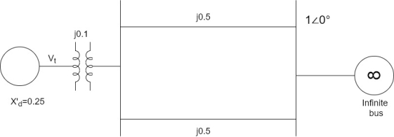
The generator of figure is delivering 1.0 pu power to The Infinite bus (|V|
= 1.0 pu), with the generator terminal voltage of |Vt|=1.0 pu calculate the generated EMF behind transient reactance full stop find the maximum power that can be transferred under the following conditions:
(a) system is healthy
(b) one line shorted three phase in the middle
(c) one line open
Plot all the three power angle curves.
Solution
Let 
From power angle equation

Or 
Or 
Current into infinite bus,


Voltage behind transient reactance,


(a) System healthy


(b) One line shorted in the middle:
As already calculated in this section,


© One line open:
It easily follows from Fig.12.7(b) that


The plot of the three power angle curves equation (i) equation (ii) and equation (iii) is drawn in figure. Under healthy condition the system is operated with Pm =B = 1.0 PU and 𝞭0=33.9 degree that is at the point P on the power angle curve 1.79 sign 𝞭. as 19 is started in the middle Pm remains fixed at 1.0 PU (governing system act instantaneously) and is further assume to remain fixed throughout the transient (governing action is slow), while the operating point instantaneously shift to Q on the curve 0.69 4 sin𝞭, at 𝞭=23.9 degree. Notice that because of machine inertia the rotor angle cannot change suddenly.

Example 4.
For figure shown below where is ford is applied at point P as shown.

Find the critical clearing angle for clearing the fault with simultaneous opening of circuit breaker 1 and 2. The reactance values of various components are indicated on the diagram. The generator is delivering 1.0 power at instant preceding the fault.
Solution
With reference to Fig 12.31 three separate power angle curves are involved.
I Normal operation(prefault)

=0.522pu


Prefault operating power angle is given by

Or 

III Post fault operation (fault cleared by opening the faulted line)


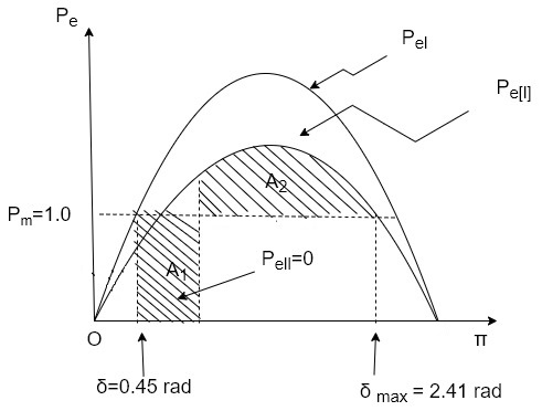
The maximum permissible angle  for area
  see Figure given by

Applying equal area criterion for critical clearing angle 


Setting  and solving


Reference & Text Books:
- “Modern power System Analysis”, By I J Nagrath, D P Kothari
- “Power System Analysis and Design”, By B R Gupta
- “Power System Stability and Control” By P. Kundur
- “Reactive Power Control” By T J E Miller
- “Power system analysis operation and control “By Abhijit Chakrabarti and Sunita Halder