Unit 2
Reactive Power management
Introduction:
AC Power system always generates Active as well as reactive power. It is important to reduce reactive power to improve system efficiency.
Real power accomplishes useful work while reactive power supports the voltage that must be controlled for system reliability. Reactive power certainly has affected power systems security, as affects the voltages profile of the overall system.
Increased demands on generation and transmission, absence of long-term planning, and the need to provide open access to generating companies and customers have resulted in less security and reduced quality of supply.
Compensation in power systems is, therefore, essential to alleviate some of these problems. Series/shunt compensation has been in use for the past many years to achieve this objective.
Following are the reason behind reactive power compensation in a system:
1) The voltage regulation
2) Increased system stability
3) Efficient utilization of connected machines, Appliances, etc.
4) Reduction in losses associated (I2R and I2X)
5) Avoid voltage swell as well as voltage sag.
For efficient and reliable operation of power systems the control of voltage and reactive power should satisfy the following objectives:
a) voltages at the terminals of all equipment in the power system are within acceptable limits. Both utility equipment and consumer equipment are designed to operate at a certain voltage rating. prolonged operation of equipment at voltages outside the certain allowable range could adversely affect their performances and possibly cause them damage.
b) stability of the system is enhanced to maximize the utilization of the transmission system. Voltage and reactive power control have a significant impact on system stability.
c) The reactive power flow is minimized to reduce I2R and I2X losses to a practical minimum to stop this ensure that the transmission system operates efficiently, i.e. mainly for active power transfer.
In a power system, the voltage at various buses tends to increase or decrease during its daily operation. To ensure the constant voltage to consumers, various techniques are utilized.
Methods of compensation:
- When the voltage is below the required level, reactive power produced by inductance needs to be offset by capacitance.
Synchronous condensers—can be used to generate reactive power, when they are operated as a motor.
Shunt capacitance —Capacitor banks can be connected in parallel to the transmission lines.
Series capacitance —Capacitors connected in series, especially for long lines can be used to raise the voltage.
Tap changing transformers—Transformer tapings can be automatically changed, to alter the voltage accordingly.
- When the voltage is above the required level, reactive power produced by capacitance needs to be offset by inductance.
Shunt reactors—Inductor banks can be connected in parallel to the transmission lines also known as reactors.
Static VAR compensators— static VAR compensator consists of a static VR generator or absorbed or device and a suitable control device.
Tap Changing Transformers—Transformer tapings can be automatically changed, to alter the voltage accordingly.
Synchronous generator Condenser:
A synchronous condenser is a synchronous machine running without a prime mover or a mechanical load. By controlling the field excitation, it can be made to either generate or absorb reactive power. with a voltage regulator, it can automatically adjust the reactive power output to maintain constant terminal voltage. it draws a small amount of active power from the power system to supply losses.
The main advantage of using a synchronous motor is that the improvement of the power factor is smooth.
Synchronous condenses are often connected to the tertiary winding of the transformer. They fall into the category of activation compensator. Because of their high purchase and the operating cost they have been largely suppressed by static VAR compensators. Recent applications of synchronous condensers have been mostly at HVDC converter stations connected to weak systems.
Synchronous compensators advantage over static compensators.
- Synchronous compensators contribute to system short circuit capacity.
- Their reactive power production is not affected by the system voltage.
- During power swings (electromechanical oscillations) there is an exchange of kinetic energy between a synchronous condenser and the power system. During such power swings a synchronous condenser can supply a large amount of reactive power, almost twice its continuous rating.
- It has about 10 to 20% overload capability for up to 30 minutes to stop unlike other forms of shunt compensation.
- It has an internal voltage source and is better able to cope with low system voltage conditions.
Effect of change of Excitation on reactive power supplied by Synchronous generator:
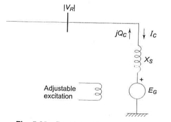
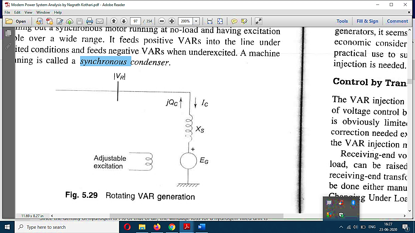
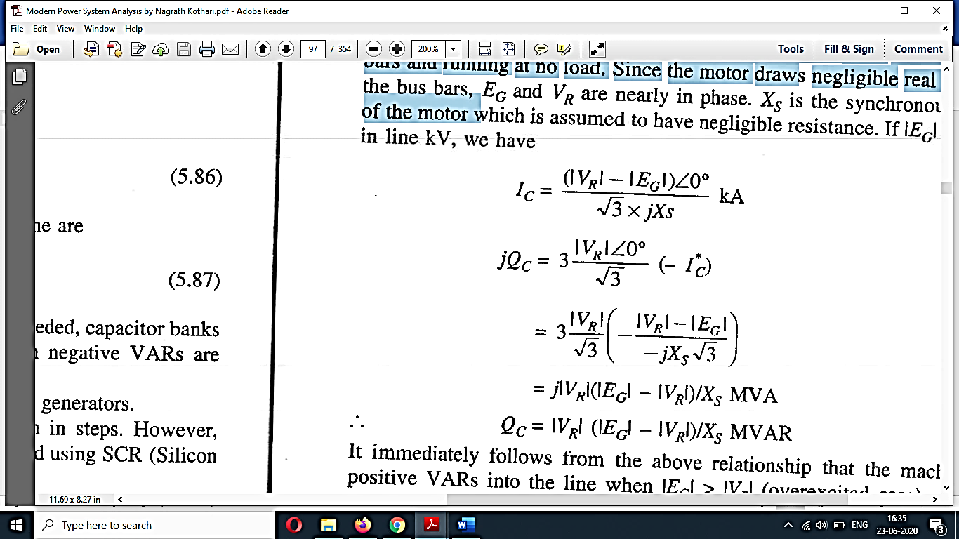
The figure shows a synchronous motor connected to the receiving bus bar and running at no load. The motor draws negligible real power from the bus bar, EG, and VR Nearly in phase. XS Is the synchronous reactance of the motor which is assumed to have negligible resistance. If |EG| and |VR| are in kv, we have,
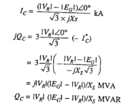
It can be seen from above that the machine fields positive v a r into the line when |EG|>|VR | (Overexcited case) and inject negative VARs if |EG|< |VR| (under excited case). VARs Are easily and continuously adjustable by existing machine excitation controls.
Because of economic considerations, installation and maintenance problems limit the use of synchronous condensers in such buses where a large amount of VAR injection is needed.
Synchronous generators are rated in terms of maximum MVA output at the specified voltage and power factor (usually 0. 85 or 0.9 leggings) which they can carry continuously without overheating. The active power output is limited by Prime mover capability to the value within the MVA rating. The continuous reactive power output capability is limited by three considerations: first armature current limit, second field current limit, and third end region heating limit.
Armature current limit:
Armature current limits the armature current results in I2R loss and is directly related to the heat of the conductor of the synchronous machine. Therefore, it imposes a limit on the operating temperature of synchronous machines.
The per-unit complex power is given by.
- Fig. Armature current heating limit
Where n is the power factor angle.
Therefore, in the PQ plane, the armature current limit as shown in the figure appears as a circle with the center at the origin and radius equals MVA rating.
Field current limit:
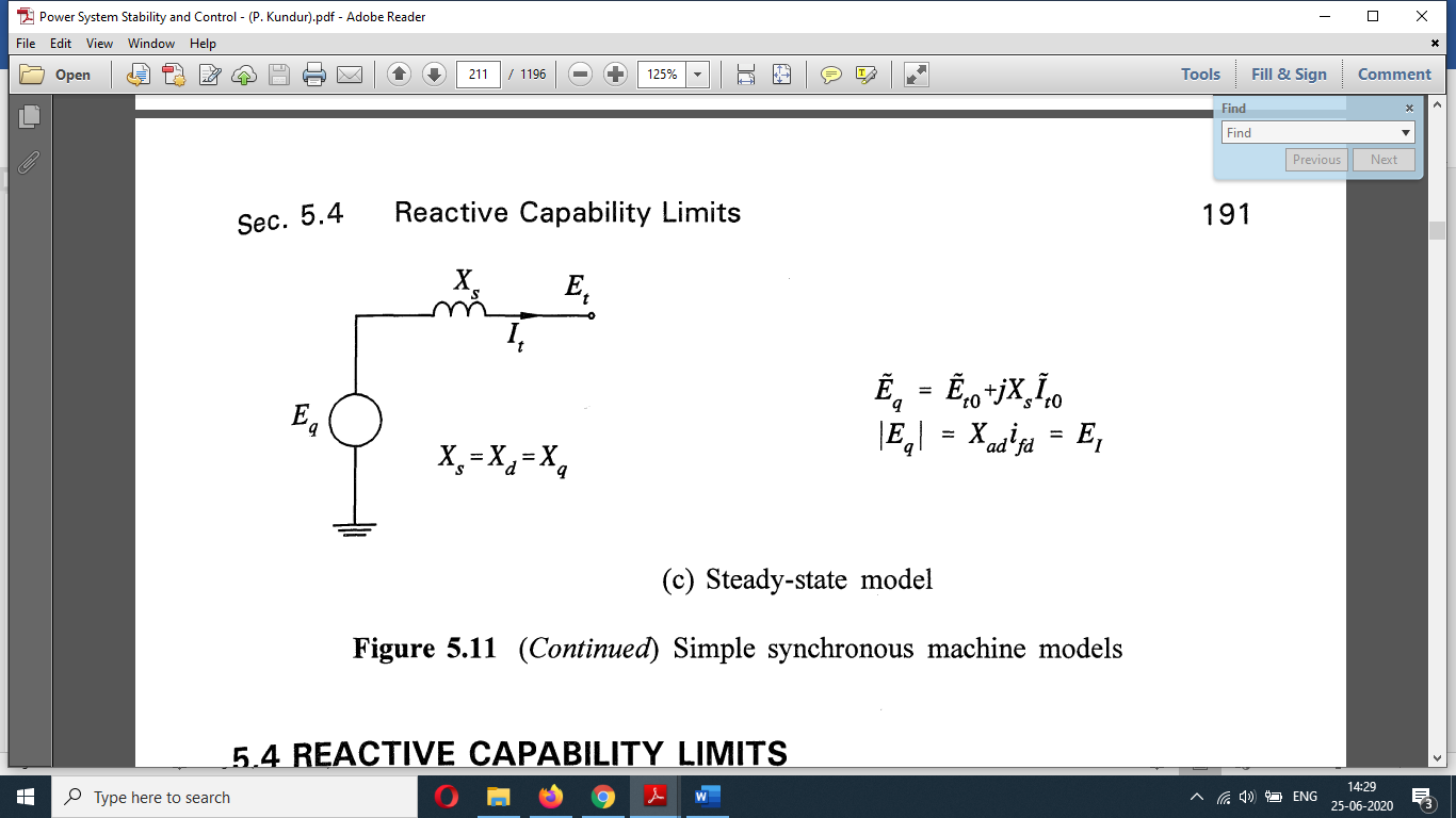
Because of the heat resulting from the I2fdRfd power loss the field current imposes the second limit on the operation of the generator.
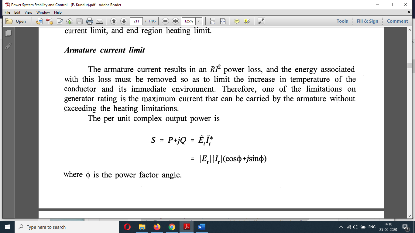
Fig. A steady-state model of a synchronous machine.
The figure above gives the relationship between Et, It, and Eq.
The constant current locus may be developed by the steady-state equivalent circuit
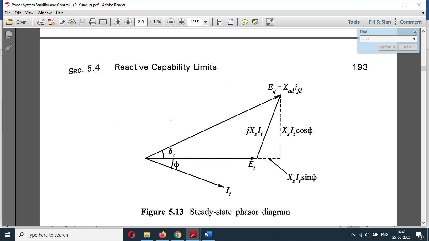
The corresponding phasor diagram with Ra neglected is shown in the figure below in a steady-state phasor diagram.
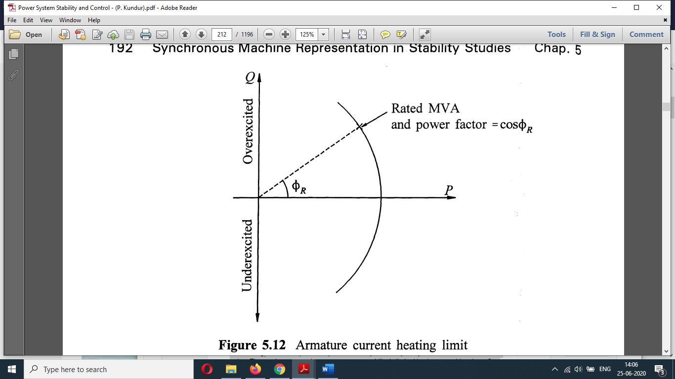
Fig: steady-state phasor diagram
Equating the components along and perpendicular to Phasor Et, we get
Therefore,
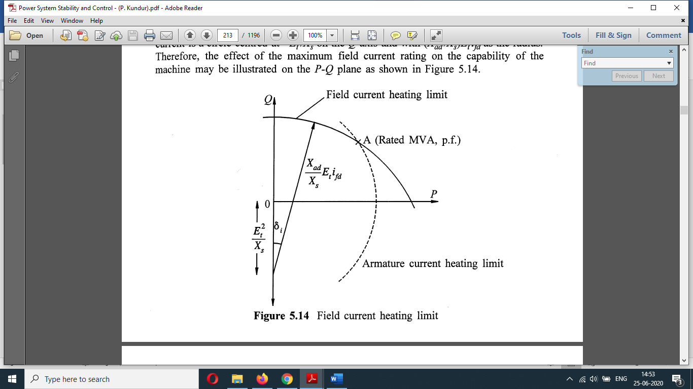
The relationship between active and reactive power for a given field current is a circle centered at -E2t/Xs by axis on capital Q axis and with (Xad/Xs) Et ifd as the radius. Therefore, the effect of maximum field current rating on the capability of machine maybe is illustrated on the capital P-Q plane as shown in the figure below.
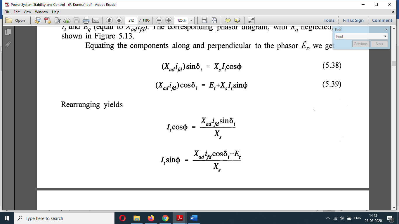
Fig: Field current heating limit
In any balanced design, thermal limits for the field and armature intersect at point A, which represents the machine nameplate MVA and power factor rating.
End region heating limit:
The localized heating in the end region of the armature imposes the third limit on the operation of synchronous machines.
This limit affects the capability of the machine in the under excited condition.
- The Eddy Currents in the lamination results in Localised heating in and region.
- The high field currents corresponding to the over-excited condition keep the retaining ring saturated, so that leakage flux is small.
- In under excited region, the field current is low, and retaining ring is not saturated this permit and increase in armature and leakage flux.
- Also, under excited condition The Flux produced by armature currents add to the flux produced by the field current, therefore the end turn flux in enhances the axial flux in the end region
- And the resulting heating effect May severely limit the generator output, particularly in the case of a round rotor machine.
This is illustrated in the figure below which also includes the limit imposed by the armature current heating effects.
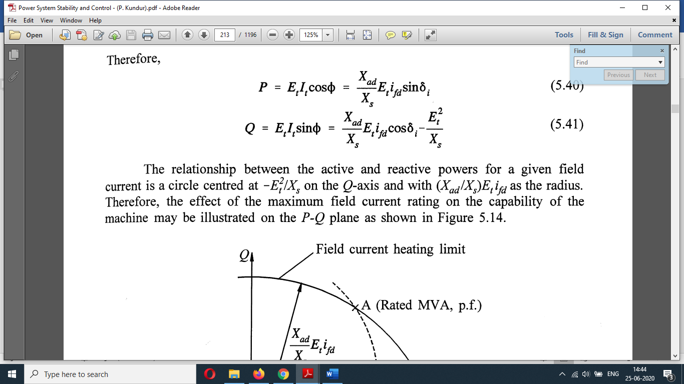
Fig. End region heating limit.
Shunt reactors:
Contractors are used to compensating for the effects of line capacitance particularly to Limit voltage rise on open circuit or light load.
They are usually required for EHV overhead lines longer than 200 km. a short line Mein also requires contractors if the line is supplied from a weak system. When the far end of the line is open the capacitive line charging current flowing through the largest source inductive reactance will cause a rise in voltage at the sending end of the line. The Ferranti effect will cause a rise in receiving and voltage.
A shunt reactor of sufficient size must be permanently connected to the line to limit the fundamental frequency temporary voltages to about 1.5pu for less than 1 second. Such line connected reactors also serve to Limit energization voltages switching transients. An additional shunt reactor required to maintain normal voltage under light load conditions may be connected to the HV bus as shown in figure (c) below, or to the tertiary winding of the adjacent Transformer as shown in figure (d) below. During heavy load conditions, some of the reactors may have to be disconnected, this is achieved by switching reactors using circuit breakers.
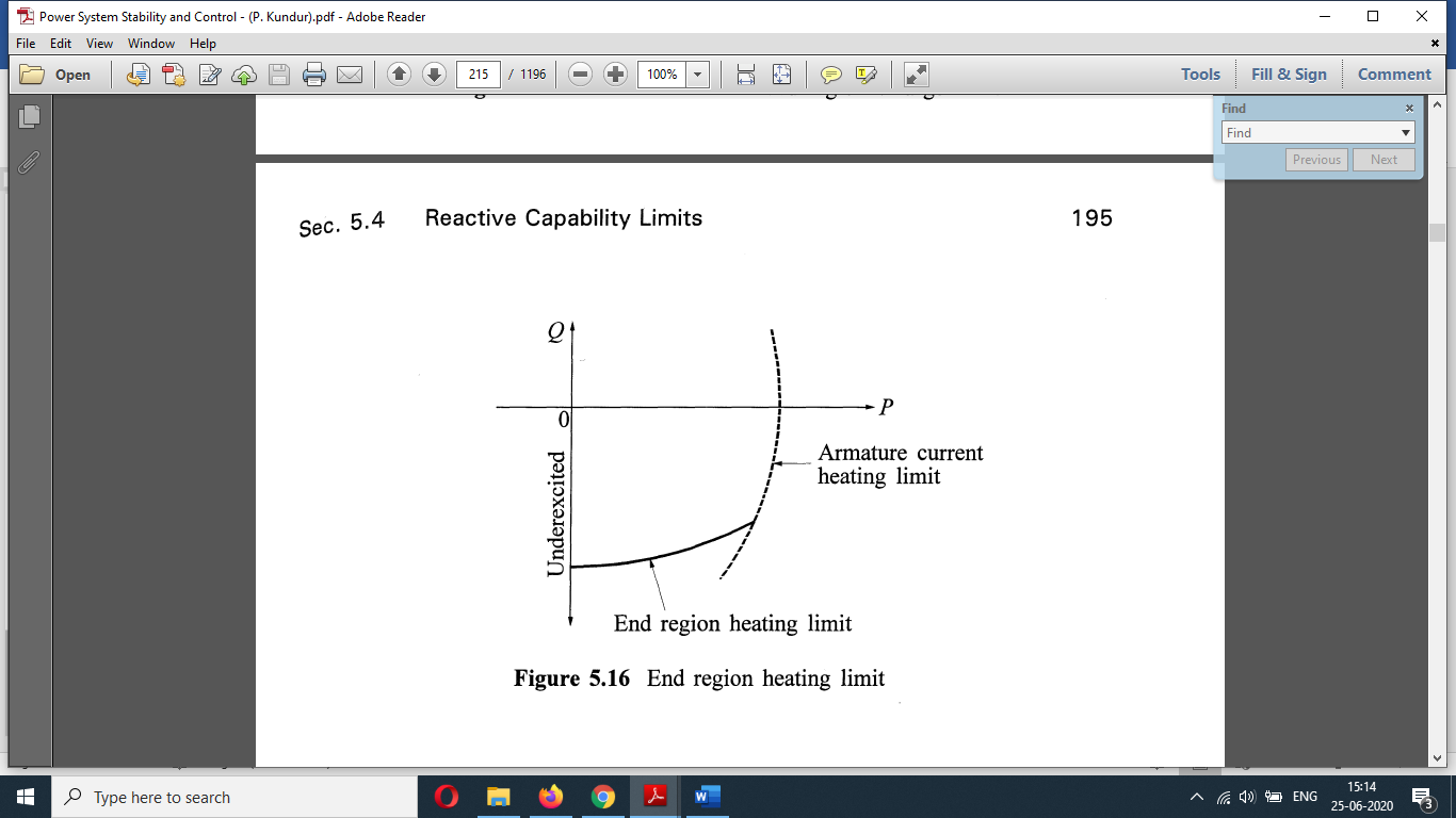
Fig (c)
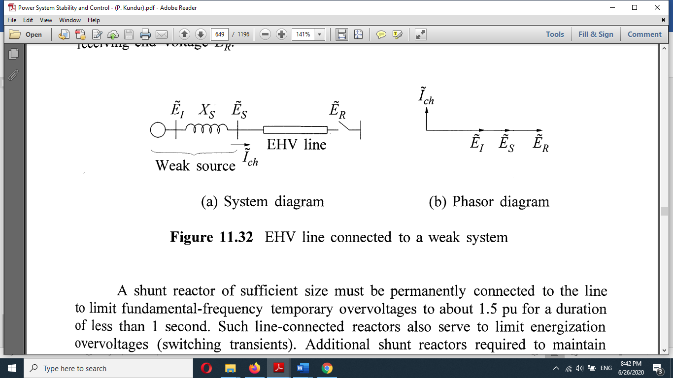
Fig (d)
For shorter lines supplied from strong systems come there may not be a need for reactors connected to the line permanently. In such cases, all the reactors use maybe switchable, connected either to the windings of the Transformer or EHV bus. In some applications tab tractors with on voltage tap change control facility have been used as shown in figure (e) below to allow variation of the reactance value.
Shunt reactors are similar in construction to Transformers, but have a single winding per phase on an iron core with air gaps and immersed in oil. They may be either single-phase or three-phase construction.
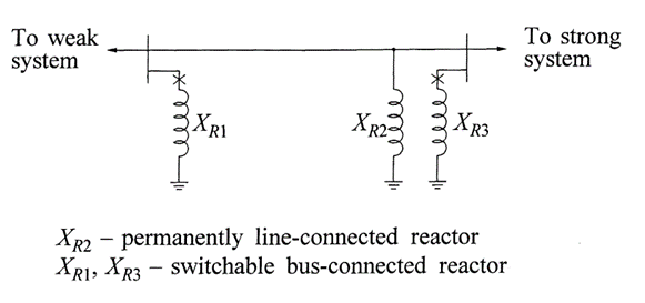
Fig. (e)
Shunt capacitors:
The shunt capacitor supplies reactive power and boosts local voltages. They are used throughout the system and are applied in a wide range of sizes.
Shunt capacitors were first used for power factor correction. The principal advantage of shunt capacitors is their low cost and their flexibility of installation and operation. They contribute to the efficiency of Power Transmission and distribution. The principal disadvantage of capacitors is that their reactive power output is proportional to the square of the voltage. Consequently, their reactive power output is reduced at low voltages when it is likely to be needed most.
Shunt capacitors application to distribution system: Shunt capacitors are used extensively in distribution systems for power factor correction and feeder voltage control. Distribution capacitors are usually Swift automatic means responding to a simple time clock, or voltage or current sensing relays.
Power factor correction is provided by means of fixed and switched shunt capacitors at various voltage levels throughout the distribution system.
Figure (f) shows power factor correction is applied at different levels first individual Motors second group of Motors third the overall plant.
Switched shunt capacitors are also used extensively for feeder voltage control.
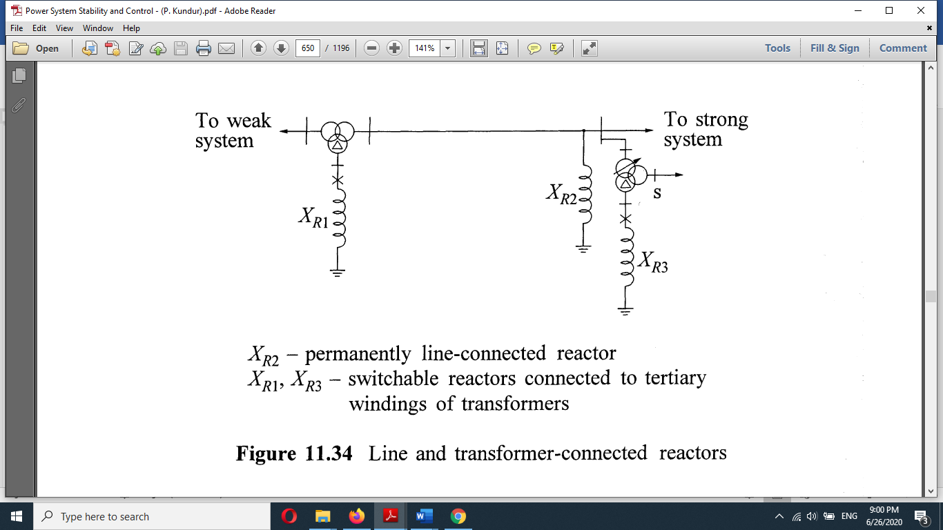
Fig (f)
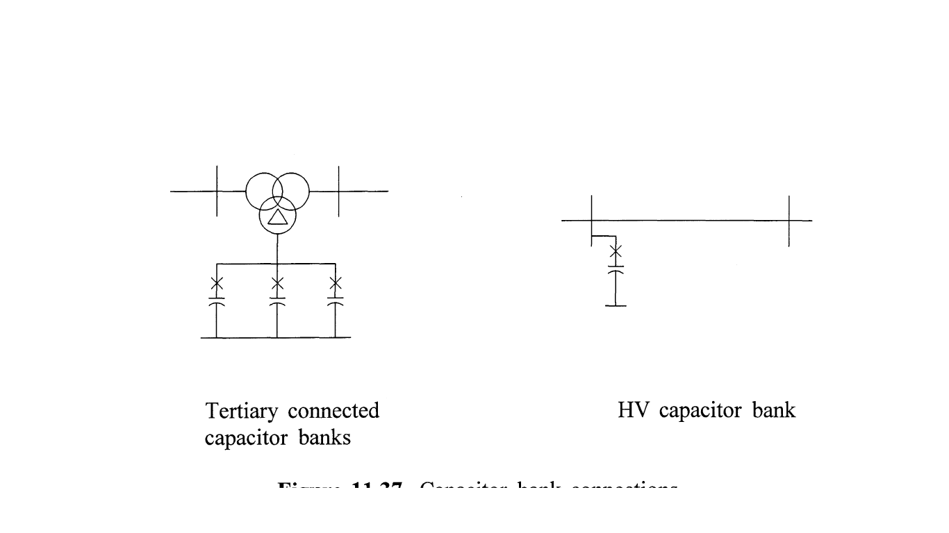
Shunt capacitor application to transmission system: Shunt capacitors are used to compensate for the I2X losses in the transmission system to ensure satisfactory voltage levels during the heavy load condition. Capacitor banks of appropriate size are connected either directly to the high voltage bus bar or the tertiary winding of the main Transformer as shown in figure (g)
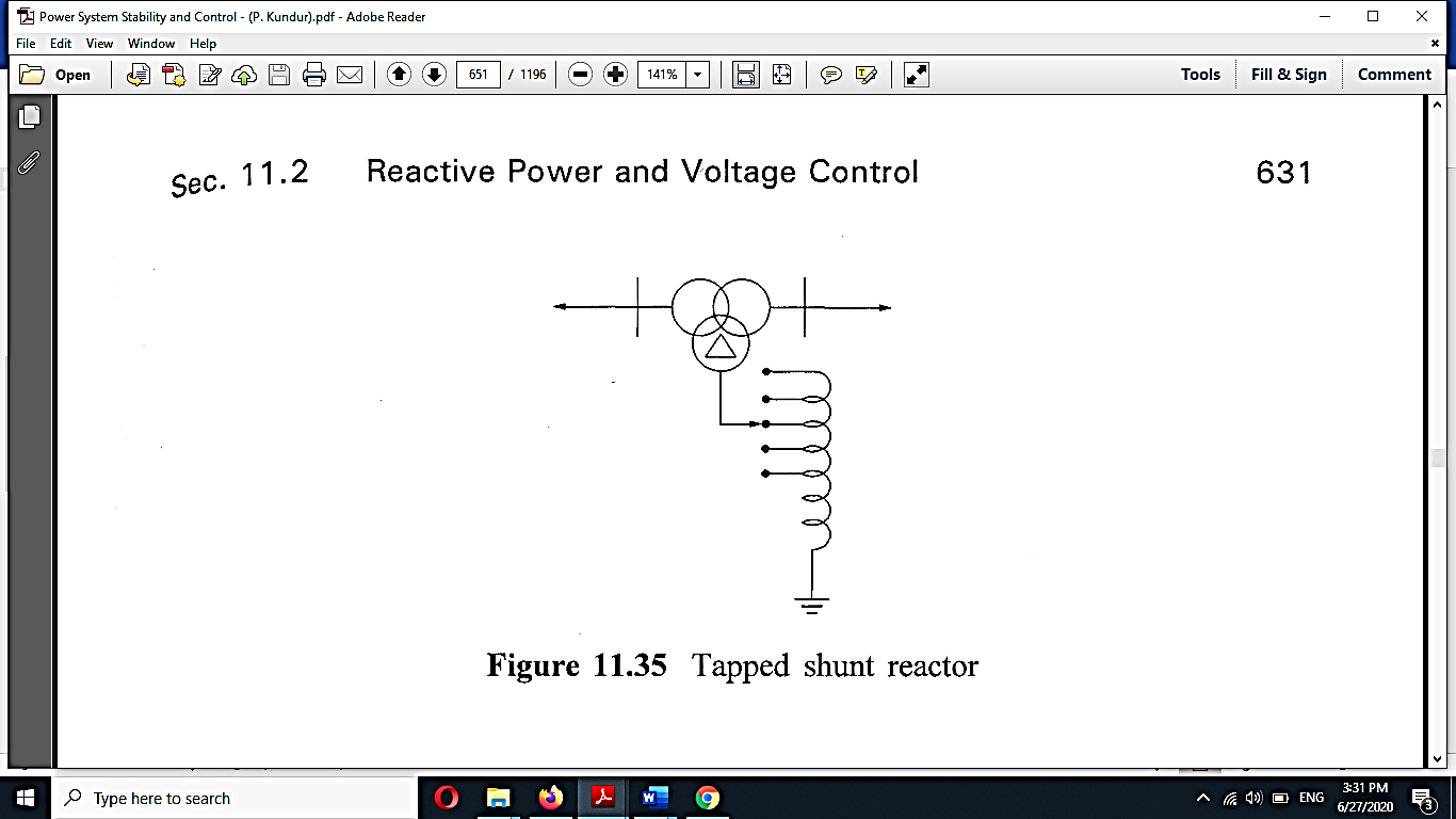
Fig. (g)
Series capacitors are connected in series with the line conductors to compensate for the inductive reactance of the line. This reduces the transfer reactance between the buses to which the line is connected, increases maximum power that can be transmitted, and reduces the effective reactive power(I2X) loss.
A series capacitor with a line gives control over the effective resistance between the line ends. This effective reactance is given by
Xl=X-Xc
Where,
Xl = line reactance
Xc = capacitive reactance
It can be seen that capacitors reduce effective line Reactance.
This results in an improvement in the performance of the system as below.
(i) voltage drop in line reduces or gets compensated (it minimizes and voltage variations).
(ii) Prevent voltage collapse.
(iii) steady-state power transfer increases.
(iv) transient stability limit increases.
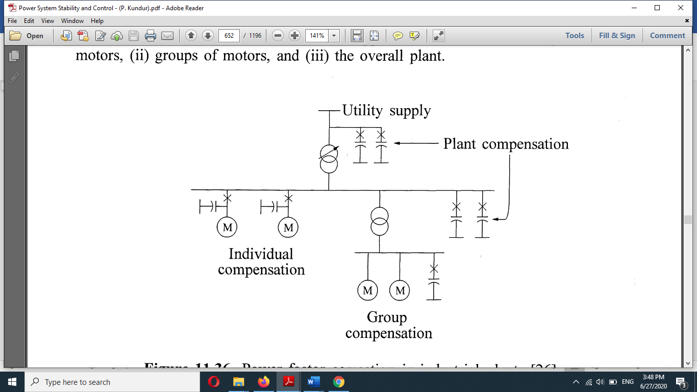
Fig (h)
As the line load, in particular, the reactive power flow over the line where there is a need to vary the compensation for adjusting the capacitance of the capacitor Bank in series with the line is shown in figure (h).
Capacitance is varied by opening the switches of individual capacitances with the capacitance C1, being started by bypass switch. This is a stepwise arrangement.
The switches can be replaced by advanced thyristor switches. which can be controlled by an advanced microcontroller for power electronics systems. This incorporates high flexibility compared to the mechanical switching of the capacitor banks or capacitors individually. Depending on capacitors and or reactors' compensation and sweet or smooth control, several compensation schemes have been devised and are in use. Some of these are
(i) Thyristor controlled series capacitor (TCSC)
(ii) Thyristor switched series capacitor (TSSC)
(III) Thyristor controlled reactor with fix capacitor (TCR-FC)
(iv) GTO Thyristor controlled series capacitor (GTCSC)
(v) Thyristor controlled reactor (TCR)
Series capacitor application to distribution feeders: series capacitors have been applied to improve the voltage regulation of distribution and industrial feeders. Welders and are furnaces are typical of loads with poor power factor and intermittent. A series capacitor not only reduces voltage drop in the steady-state, but it responds almost instantaneously to changes in the load current. The series capacitor by reducing the impedance between the bulb power source and fluctuating load is effective in solving flicker problems.
Series capacitor application to EHV transmission system: series capacitors are primarily used to improve the system stability and obtain desired load division among parallel lines. The practical upper limit of series compensation is about 80%.
Series compensation:
Series controllers: the series controller could be a variable impedance, such as capacitor reactor, etc. or Power Electronics based variable source of main frequency, sub-synchronous and harmonic frequencies, or combination to serve the desired need. Mainly, all series controllers inject voltage in series with the line. Even a variable impedance multiplied by the current flow through it, reports, and injected series voltage in the line. As long as the voltage is in phase quadrature with the line current, the series controller only supplies or consumes variable reactive power. Any other phase relationship will involve the handling of real power as well.
Series compensation is a powerful tool to improve the performance of EHV lines. It consists of a capacitor connected in series with the line at suitable locations.
Advantages of series compensation:
The use of series compensation leads to many advantages relating to power transfer capability, voltage regulation, etc. These are as follows:
(a) Increase in transmission capacity:
The power transfer P over a line is given by-
 (1)
(1)
Vs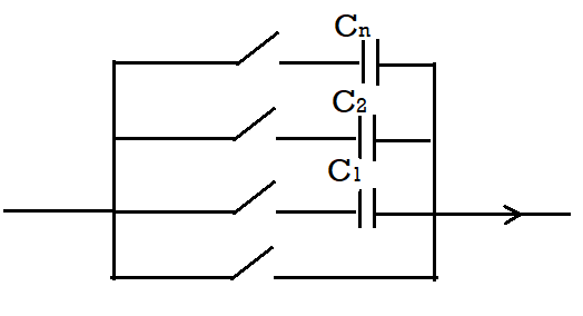 δ = sending end voltage.
Vr =receiving end voltage.
XL = inductive reactance of the line.
δ = Phase angle between Vs and Vr
In series capacitor having capacitive reactance, Xc is inserted, the net series reactance becomes XL-Xc and the power transfer P2 is given by-
 (2)
(2)
From equations 1 and 2 It is seen that for the same magnitude of Vs, Vr, and δ, theP2 is higher than P1.
The increase in power transfer is given by –
 (3)
(3)
 and is known as the degree of compensation. The economic degree of compensation lies between 40% & 70%.
(b) Improvement of stability:
From the above equations, It is seen that the same amount of power transfer and the same values of Vs and VR the phase angle δ in case of the series compensated line is is less than that of a compensated line. It is known that lower anger dead means better system stability.
Series compensation generally offers the most economic situation with respect to both the steady-state and transient stability.
(c) Load division between parallel circuits:
The reduction of series directed by series compensation makes it a useful tool to balance the loading in parallel circuits to stop when the system is strengthened by the addition of a new line or when one of the existing circuits is to be adjusted for the parallel operation to achieve maximum power transfer and minimize losses the series compensation can be used to great advantage.
Location of series capacitors: the choice of the location of the series capacitor depends on many technical and economic considerations.
Three commonly used locations are:
(a) the location along the line: in this method, the capacitor bank is located in the middle of the line. This location has advantages of better voltage profile along the line, short circuit current through the capacitor in the event of a fault, and simpler protection of the capacitor.
(b) Location at one or both ends of the line section on the line sides in the switching station: The main advantage of this location is that the capacitor installation near the manned station.
(c) The location between bus bars Was within the switching stations: the advantage of this location is that the capacitor installation is concentrated at a few accessible places within the switching station. This requires a little complicated and expensive switching arrangement.
Problems associated with series compensation:
(a) sub-synchronous resonance: Series capacitor introduces sub-synchronous frequency in the system. In some cases, this frequency may interact with weak steam turbine generator shafts and give rise to high torsional stresses.
(b) Ferroresonance: When an unloaded or lightly loaded transformer is energized through series compensator line ferroresonance may occur. The frequency of oscillation is an integral multiple of system frequency.
(c) Line protection: Series compensation can lead to Mal operation of the distance release of line protection if the degree of compensation and capacitor locations are not proper.
(d) High recovery voltage: series voltage capacitors produce high recovery voltages across the circuit breaker contacts.
Reference & Text Books:
- “Modern power System Analysis”, By I J Nagrath, D P Kothari
- “Power System Analysis and Design”, By B R Gupta
- “Power System Stability and Control” By P. Kundur
- “Reactive Power Control” By T J E Miller
- “Power system analysis operation and control “By Abhijit Chakrabarti and Sunita Halder