UNIT 3
FACTs Technology
In AC power systems because of the insignificant electrical storage, the electrical generation and load must balance at all times.
To some extent the electrical system is self-regulating- if generation is less than the load, the voltage and frequency drop, and thereby the load goes down to equal the generation minus the transmission losses. However, there is only a few percent margin for search self-regulation.
Voltage collapse problem- If the voltage is supported with the reactive power support, then the load will go up, and consequently the frequency will keep dropping and then the system will collapse. Alternatively, if there is inadequate reactive power the system can have voltage collapse.
Surplus generation power flow problem- When surplus generation is available, it can flow towards the area where there is deficiency in generation. This happens without any control power, flow is based on the inverse of the various transmission line impedances bus stop apart from ownership and contractual issues over the line which carry how much power coma it is likely that the lower impedance line may become overloaded and thereby limit the loading on both parts even though the higher impedances path is not fully loaded.
Solution to Problems of AC transmission system by using FACTS Technology:
Consider a very simple case of power flow shown in figure (a), two parallel paths from a Surplus generation area, an equivalent generator on left, to a deficit generation area on the right, without any control power flow is based on the inverse of the various transmission line impedances.
Alternative FACTS controllers (figure b) and (figure c) show one of the transmission lines with different types of series type FACTS controller. By means of controlling impedance (figure b) for phase angle (figure c) or series injection of appropriate voltage FACTS controller can control the power flow as required maximum power flow can in fact be limit to its rated limit under contingency conditions when this line is expected to carry more power due to the loss of parallel lines.
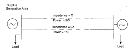
Fig. (a)

Fig. (b)

Fig. (c)
The FACTS technology is not a single high-power controller, but rather a collection of controllers, which can be applied individually or in coordination with others to control one or more of inter-related system parameters.
FACTS Technology extends itself to usable transformation limits in the step-by-step manner with the incremental investment as and when required.
Some of the power electronics controllers, now used and converted into the FACTS concept lead the introduction of the FACTS concept.
The shunt connected static VAR compensator (SVC) for voltage control which was first demonstrated in Nebraska and commercialized BY GE in 1974 and by Westinghouse in Minnesota in 1975.
The first series connected controller, NGH-SSR damping scheme, a low power series capacitor impedance control scheme, was demonstrated in California by Siemens in 1984. It showed that with an active controller there is no limit to series capacitor compensation.
Even prior to SVCs, there are two versions of static saturable reactors for limiting over voltages and also powerful gapless metal oxide arresters for limiting dynamic voltage.
The Development of FACTS controllers:
The development of FACTS controllers has followed two different approaches. The first approach employs reactive impedances or a tap changing transformer with thyristor switches as controlled elements, the second approach employs self-commutated static converters as controlled voltage sources. Ln general, FACTS controllers can be divided into four categories. (i) series (ii) shunt (iii) combined series-series(iv) combined series-shunt controllers.
The general symbol for a FACTS controller is given in Fig. (a). It shows a thyristor arrow inside a box. The series controller of Fig. b could be a variable impedance, such as capacitor, reactor, etc. or a power electronics based variable source. All series controllers inject voltage in series with the line. If the voltage is in phase quadrature with the line, the series controller only supplies or consumes variable reactive power. Any other phase relationship will involve real power also.
The shunt controllers of Fig. c may be variable impedance, variable source or a combination of these. All shunt controllers inject current into the system at the point of connection. Combined series-series controllers of Fig. d could be a combination of separate series controllers which are controlled in a coordinated manner or it could be a unified controller. 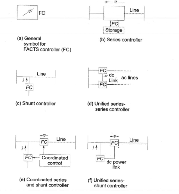
Combined series-shunt controllers are either controlled in a coordinated manner as in Fig. e or a unified Power Flow Controller with series and shunt elements as in Fig. f. For unified controller, there can be a real power exchange between the series and shunt controllers via the dc power link.
The group of FACTS controllers employing switching converter-based synchronous voltage sources include the Static synchronous Compensator (STATCOM), the static synchronous series compensator (SSCC), the unified power flow controller (UPFC) and the latest, the Interline Power Flow Controller (IPFC).
STATCOM is a static synchronous generator operated as a shunt-connected static var compensator whose capacitive or inductive output current can be controlled independent of the system voltage. The STATCOM, the SVC, controls transmission voltage by reactive shunt compensation. It can be based on a voltage-sourced oi current-sourced converter. Figure (g), (h) shows a one-line diagram of SATCOM based on a voltage-source converter and a current sourced converter. Normally a voltage source converter is preferred for most converter-based FACTS controllers. STATCOM can be designed to be an active filter to absorb system harmonics. 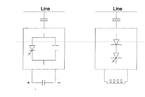
Fig (g) Fig (h)
A combination of STATCOM and any energy source to supply or absorb power is called static synchronous generator (SSG).
Limits on Loading Capability of transmission system:
There are three kinds of limitations
Thermal
Dielectric
Stability
Thermal:
Thermal capability of an overhead line is a function of ambient temperature, wind conditions, condition of the conductor, and the ground clearance. It is by a factor of 2 to 1 due to the variable environment and unloading history. The nominal rating of a line is generally decided by keeping in mind the worst ambient environment.
Dielectric:
From an insulation point of view, many lines are designed with very conservative limits. For the given nominal voltage rating, it is often possible to increase the normal operating condition by + 10% voltage or even higher. Care is needed to ensure that dynamic and transient overvoltage are within limits.
Stability:
There are number of stability issues that limit the transmission capability, these are-
Transient stability
Dynamic stability
Steady state stability
Frequency collapse
Voltage collapse
Sub synchronous resonance
Principle of operation, circuit diagram and applications of SVC
Static Var compensator (SVC): It is a Series connected static var generator or absorber whose output is adjusted to exchange capacitive or inductive current so as to maintain control specific parameters of the electrical power system (typically bus voltage).
This is a general term for a thyristor controlled or thyristor switched reactor and or thyristor switched capacitor or combination. SVC is based on thyristor without the gate turn off capability. It includes separate equipment for leading and lagging var, the thyristor controlled or Thyristor switch reactor for absorbing reactive power and thyristor switched Capacitor for supplying reactive power.
Shunt Compensators:
Shunt compensators are connected in shunt at various system nodes (major substations) and sometimes at mid-point of lines. These serve the purposes of voltage control and load stabilization. As a result of installation of shunt compensators in the system, the nearby generators operate at near unity pf and voltage emergencies mostly do not arise. The two kinds of compensators in use are:
(i) Static var compensators (SVC): These are banks of capacitors (sometimes inductors are also used under light load conditions)
(ii) STATCOM: static synchronous compensator:
Static var compensators (SVC):
SVCs are part of the Flexible AC transmission system device family, regulating voltage and stabilizing the system. Unlike a synchronous condenser which is a rotating electrical machine, a "static" VAR compensator has no significant moving parts. Prior to the invention of the SVC, power factor compensation was the preserve of large rotating machines such as synchronous condensers or switched capacitor banks.
These comprise capacitor bank fixed or switched (controlled) or fixed capacitor bank and switched reactor bank in parallel. These compensators draw reactive (leading or lagging) power from the line thereby regulating voltage, improve
Stability (steady state and dynamic), control voltages and reduced voltage flicker. These also reduced voltage and current unbalances. In HVDC application these compensators provide the required reactive power and dump out sub-harmonic oscillations.
Since var compensators use switching for var control. These are also called static var switches or systems.
Basic configuration of SVC: thyristor in antiparallel can be used to switch a capacitor/ Reactor in stepwise control. when the circuitry is designed to adjust the firing angle capacitor/ reactor unit acts as continuously variable in the power circuit.
Capacitor for capacitor and inductor Bank can be varied stepwise or continuously by control of thyristor. Several important SVS configurations have been devised and are applied in shunt compensation. Some of these are saturated reactors, Thyristor control reactors, Thyristor switched capacitors.
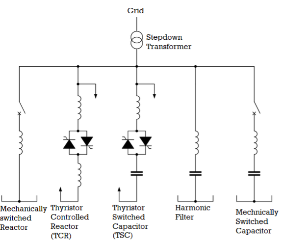
Fig. One-line diagram of a typical SVC configuration
SVC and STATCOM V-I characteristics:
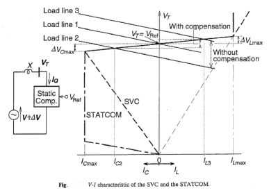
A typical terminal voltage versus output current characteristics of static compensator with specific slope is shown in figure, together with particular load lines (Voltage vs reactive current characteristics) of the AC system. load line 1 intersects the compensator V-I characteristics at the nominal voltage, 10 output current of the compensator is zero. load line to is below load line one due to the decrease in the power system voltage (e.g. generator outage). its intersection with the compensator v-i characteristics called for the capacitive compensating current Ic2. load line 3 is a below line 1 due to the increase in the power system voltage (e.g. load rejection), its intersection with the compensator V-I characteristics defines Inductive compensating current IL3. the intersection points of the load lines 2 and 3 with vertical voltage access defines the terminal voltage variation without any compensation. The Terminal voltage variation with compensation, in the linear operating range under steady state condition and slow system changes is entirely determined by the regulations slope, independent of the type of VAR generator used, can be seen in figure. outside of the linear operating range of the STATCOM and SVC act differently as indicated in figure. The dynamic performance of the two types of compressor is also different.
Several important SVS configurations have been devised and are applied in shunt line compensation. Some of the static compensator’s schemes are discussed below.
Self-saturated reactor (SR): The variable element in an iron core reactor working in the Saturated region and capacitor bank is in parallel it does not require any control system and automatically adjusts its loading so that required by the system. To match its characteristics to the system requirement, it may be necessary to reduce the slope reactance of the saturated reactor by connecting a slope correction capacitor in series. The saturated reactor, being of Transformer type construction, has very high short time more load capacity and is therefore very suitable for holding down the system dynamic overvoltage such as those resulting from load rejection.
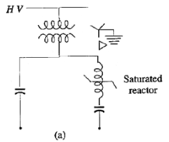
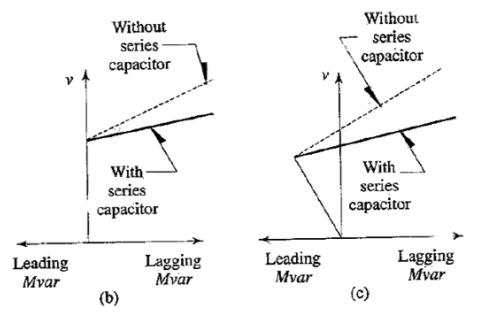
The saturated reactor is a self-regulating device that responds to only changes in its terminal voltage. The voltage regulation characteristics are dependent on the natural situation characteristic of the iron core reactor, the rating of a series capacitor for saturation slope compensation. Figure (b) shows characteristics without shunt capacitor and figure (c) shows characteristics which and capacitor. The saturated reactor for ratings up to 132KV can be directly connected to the bus bar. However, an intermediate transformer is needed for higher voltages.
Thyristor controlled reactor (TCR):
A basic single-phase thyristor-controlled reactor (TCR) is shown in figure below. It consists of a fixed reactor (usually air Core) of inductance L, and a bi-directional thyristor valve (or switch). Thyristor valve can be controlled by a gate pulse. the valve will automatically block immediately after The AC current crosses zero, unless the gate signal is reapplied.

Fig. (a) TCR, (b) Operating characteristics
The current in the reactor can be controlled from maximum (thyristor valve closed) to zero (thyristor valve open) by the method of firing delay angle control. that is the closure of thyristor valve is delayed with respect to the peak of the applied voltage in each half cycle, and thus the duration of current conduction interval is controlled. The amplitude ILF(a) of the fundamental current ILF(α) can be expressed as a function of ‘α’.

The TCR can control fundamental current continuously from zero to maximum as if it is a variable reactive admittance. Thus, an effective reactive ad mittens BL(α) for the TCR can be defined. This admittance as a function of angle can be written directly from equation as below-

The admittance varies with the  in the same manner as the fundamental current. This means at each delay angle α an effective admittance can be defined, which determines the magnitude of fundamental current in the TCR at given applied voltage.
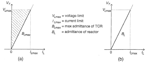
TCR can be operated anywhere in a defined V-I area, the boundaries of which are determined by its maximum attainable admittance, voltage, and current ratings, as illustrated in figure (a) below. If the TCR switching is restricted to a fixed angle, usually α = 0, then it becomes a thyristor switched reactor (TSR). TSR provides a fixed admittance and thus, when connected to the DC system, the reactive current in it will be proportional to the applied voltage, as shown in V-I plot figure (b).
Thyristor controlled reactor (TCR) - Fixed capacitor (FC):
The TCR-FC system shown in figure (a) below, provides continuously controllable lagging to leading VARs through thyristor control of Reactor current. Leading VAR are supplied by two or more fix capacitor banks. the teacher is generally rated larger than the total fixed capacitance so that net legging VARs Can also be supplied. The variation of current through the reactor is obtained by phase control of back to back pairs of thyristor valves connected in series with the reactor. Arranging the TCR and coupling Transformer secondary in Delta serves to cancel third harmonics.
The reactive power output versus terminal voltage steady state characteristic shown in figure (b). The slope of the characteristics in the regulation interval is determined by the control of the firing angle. Outside the regulation interval the characteristic is same as that of a capacitor or an inductor.

Fig. (a) connection diagram, (b) Characteristics for
Thyristor controlled Reactor (TCR) and Fixed Capacitor (FC) for shunt compensation
(figure source: Power system analysis and Design by B. R. Gupta)
Thyristor switched capacitor:
It consists of only Thyristor switched capacitor bank which is split into a number of units of equal ratings to achieve step wise control shown in figure below.
TSC is characterized by step wise control, no transients, low harmonics losses, redundancy and flexibility.
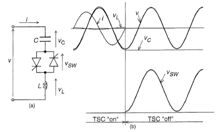
Single phase thyristor switched capacitor TSC is shown in figure (a). It consists of a capacitor, bidirectional thyristor valve, and a relatively small search current limiting reactor. This reactor is needed primary lead to limit the search current in the thyristor valve under abnormal conditions (e.g. control malfunction causing capacitor switching at a wrong time, when transient free switching conditions are not satisfied); it may also be used to avoid resonance with ac system impedance at a particular frequency.
Under steady state condition, when the thyristor valve is closed and TSC is connected to a sinusoidal AC voltage source  , The current in the branch is given by
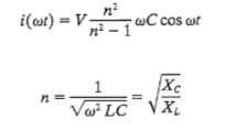
The amplitude of the voltage across the capacitor is\

The TSC branch can be disconnected at any current zero by prior removal of gate drive to the wall full stop at the zero crossing, the capacitor voltage is at its peak value, the disconnected capacitor stays charge to this voltage and consequently the voltage across the non-conducting thyristor wall where is between 0 and peak to peak value of the applied AC voltage, as shown in figure (b) above.
The maximum Possible delay in switching in a capacitor bank is one full cycle of applied AC voltage, that is, the interval from one positive (negative) peak to the next causes (negative) peak. The firing delay angle control is not applicable to the capacitor; the capacitor switching must take place at a specific instant in each cycle at which the conditions for maximum transient is satisfied, that is, when the voltage across the thyristor wall is zero or minimum. For this reason, TSC branches can provide only step-like change in a reactive Karan it draws (maximum or zero).
The current in the TSC branch where is linearly with the applied voltage according to the admittance of the capacitor and illustrated by the plot in figure (operating V-I area of single TSC) below.

The maximum applicable voltage and corresponding current are limited by the ratings of TSC components (capacitor and thyristor valve). To approximate continuous current variation, several TSC branches in parallel may be used.
Combined TCR and TSC Compensator:
The solid-state switch in series with the reactor bank is composed of reverse parallel connected thyristor pairs (In actual practice many branches in pairs are connected in series to provide in the voltage rating) and is capable of continuously controlling current in the reactor from 0 to rated value. Similarly, the switch in series with each capacitor bank consists of rivers parallel connected thyristor pairs.
Thus, TSC-TCR scheme has the capability to provide the leading and lagging vars both independently and rapidly. advantages of TCR scheme over the TCR-FC scheme are, improved performance during large system disturbances and lower losses. This system is characterized by continuous control, no transient, low generation of harmonics, low losses, redundancy, flexible control and operation.
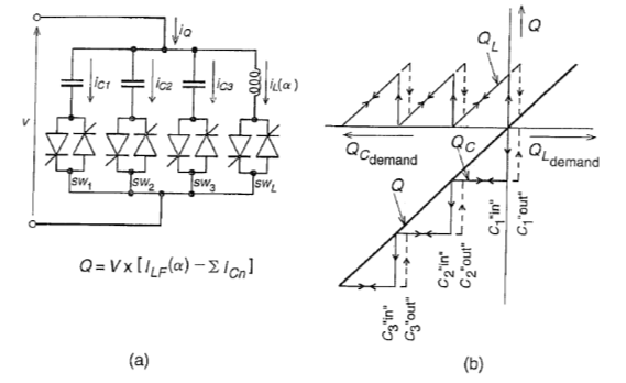
Fig. (a) Combined TCR and TSC Compensator, (b) var demand vs output characteristics
The basic single phase TSC-TCR arrangement shown in figure (a). For a given capacitor output range, it typically consists of ‘n’ number of TSC branches and one TCR. The number of branches is determined by a practical consideration like the operating voltage, Maximum var output, current rating of the thyristor valves, bus work and installation cost, etc. inductive expanded to by TCR branches.
The operation of basic TSC-TCR is shown in figure (a), The functioning of this is as follows.
The total capacity output range is divided into n intervals. In the first interval, the output of the var generator is controllable in the zero to Qmax/n range, where, Qmax is the total rating provided by all TSC branches. In this interval, one capacitor bank is switched in (by firing) and simultaneously, the current in TCR is set by the appropriate firing delay angle so that the sum of the var output of the TSC (negative) and of that the TCR (positive) equals the capacitive output required.
By being Able to switch the capacitor Bank in and out within one cycle of the applied AC voltage, the maximum surplus capacity of var in the total output range can be restricted to that produced by one capacitor bank and thus Theoretically, the TCR should have the same var Rating as the TSC. But the rating of the TCR has to be somewhat larger in Practice then that of one TSC in order to provide overlap (hysteresis) between switching in and switching out var levels. The var demand versus output characteristic of the TSC-TCR type var generator is shown in figure (b). Also, the V-I characteristic of the TSC-TCR type var generator for two TSC is shown in figure (c) below.
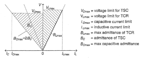
Fig (c) operating V-I area of the TSC-TCR with two thyristor switched capacitor banks.
STATCOM: (Static Synchronous Compensator): static generator operated as shunt connected static var compensator whose, capacitive for inductive output current can be controlled independent of the AC system voltage.
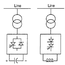
Fig. (a) Simple one line diagram of STATCOM (Voltage source converter based and Current source converter based)
STATCOM Is one of the key FACTS controllers. it can be based on a voltage source or current source converter; figure shows a simple one line diagram of a STATCOM based on voltage source converter and a current source converter. from an overall cost point of view, voltage source converters are preferred.
For the voltage source converter, ac output voltage is controlled such that it is just right for the required reactive current flow for any bus voltage DC capacitor voltage is automatically adjusted as required to serve the voltage source for the. Convert STATCOM can be designed to act as an active filter to absorb system harmonics.
STATCOM in power systems is used to increase the power transmission capability with a given transmission network from the generators to the loads. A static constructor cannot generate or absorb real power; the reactive output power of the compensator is varied to control the voltage at given terminals of the transition network so as to maintain desired power flow under possible system disturbances and contingencies.
Typical terminal voltage versus output current characteristic of static compensators with the specific slope is shown in figure below. Together with particular load lines (Voltage versus load current characteristics) of the AC system. Load line one intersects the compensator v-i characteristics at nominal voltage, does the output current of the capacitor is zero. do line to is below line want you to the decrease in the power system voltage (e.g. generator outage). Its intersection with the compensator v-i characteristics calls for the capacitive compensating current Ic2. (e.g. Load rejection). its interconnection with the compensator v-i characteristics define the inductive compensation current Il3. the intersection points of The Road Lines 2 and 3 with the vertical (voltage) axis defined the terminal voltage variation without any compensation. The Terminal voltage variation with the compensation in the linear operating range under steady state condition and slow system changes is entirely determined by the regulations lo which is independent of the type of VR generator used as can be seen in figure below. outside the linear operating range, the STATCOM and SVC are differently as indicated in figure. The dynamic performances of the two types of computer is also different.
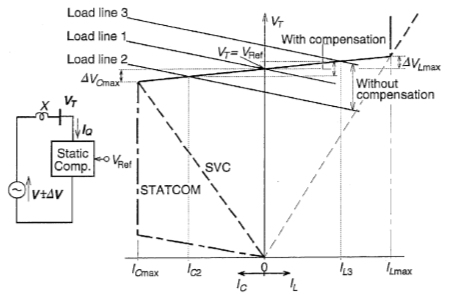
Fig (b): V-I Characteristics of STATCOM and SVC
Comparison between STATCOM and SVS:
The basic operational difference renders the STATCOM to have
- Overall superior functional characteristics
- Better for performance
- Performance and greater application flexibility as compared to SVC.
- The ability of the STATCOM to maintain full capacity output current at low system voltage also makes it more effective than SVC in improving the transient (first swing) stability.
Advantages of series compensation:
(i) Series capacitors are inherently self-regulating and a control system is not required.
(ii) For the same performance, series capacitors are often less costly than SVCs and losses are very low.
(iii) For voltage stability, series capacitors lower the critical or collapse voltage.
(iv) Series capacitors possess adequate time-overload capability.
(v) Series capacitors and switched series capacitors can be used to control loading of parallel lines to minimise active and reactive losses.
Disadvantages of series compensation:
(i) Series capacitors are line connected and compensation is removed for outages and capacitors in parallel lines may be overloaded.
(ii) During heavy loading, the voltage on one side of the series capacitor may be out of range.
(iii) Shunt reactors may be needed for light load compensation.
(iv) Sub-synchronous resonance may call for expensive countermeasures.
Advantages of SVC
- SVCs control voltage directly.
- SVCs control temporary over voltages rapidly.
Disadvantages of SVC:
- SVCs have limited overload capability.
- SVCs are expensive.
Thyristor controlled series capacitor (TCSC):
Reactance compensator which consists of a series capacitor Bank sheltered by thyristor-controlled reactor in order to provide smoothly variable series capacitive reactance is called as thyristor control series capacitor (TCSC).

Fig. Thyristor controlled series capacitor
The TCSC is based on thyristors without the gate turn off capability. a variable reactor such as a thyristor-controlled reactor (TCR) is connected across a series capacitor. When the TCR firing angle is 180 degrees, the reactor becomes non conducting and the series capacitor is normal. as the firing angle is advanced from 180 degrees to less than 180 degrees, the capacitive impedance increases. At the other end, when the firing angle is 90 degrees, the reactor becomes fully conducting, and the total impedance becomes in the, because the reactor impedance is designed to be much lower than the series capacitor impedance. With 90° firing and, the TCSC health in limiting fault current. The TCSC may be a single large unit, or may consist of several equal or different size smaller capacitors in order to achieve a superior performance.
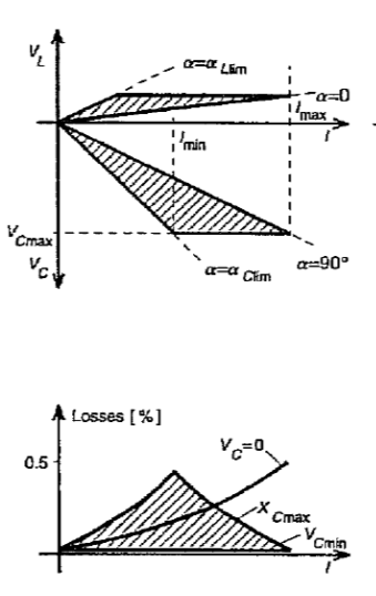
Fig. Compensating Voltage Vs Line Current and corresponding loss Vs Line current characteristics of TCSC.
TCSC is a variable inductance type series compensator.
TCSC can maintain maximum compensating voltage with a decreasing line current over a control range determined by the current boosting capacity of the thyristor-controlled reactor.
The TCSC employ conventional thyristors (with no internal turn off capability). And these have the highest current and voltage ratings and also highest surge current capability.
At rated line currents the losses of the reactors are around 0.5% can be seen in fig above.
Unified Power Flow Controller (UPFC):
A combination of static synchronous compensator(STATCOM) and static series compensator (SSSC) which are coupled via a common DC link, to allow bi directional flow of real power between the series output terminals of the SSSC and the shunt output terminals of the STATCOM, and are controlled to provide concurrent real and reactive series line compensation without an external electrical energy source. The UPFC by means of angularly unconstrained series voltage injection, is able to control, concurrently or selectively, that transmission line voltage, impedance and angle or, alternatively, the real and reactive power flow in the line. UPSC may also provide independently controllable shunt reactive compensation.
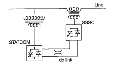
Fig. (a) UPFC
In UPFC figure shown above, it combines a STATCOM and an SSSC, the active power for series unit SSSC is obtained from line itself via the shunt unit STATCOM; the letter is also used for voltage control of its reactive power. This is a complete controller for controlling active and reactive power control through a line, as well as line voltage control.
Additional storage such as superconducting magnet connected to the DC link wires and electronic industries would provide the means of further enhancing the effectiveness of UPFC. the controlled exchange of real power with an external source, such as storage, it is much more effective in control of system dynamics than modulation of the power transfer within a system.
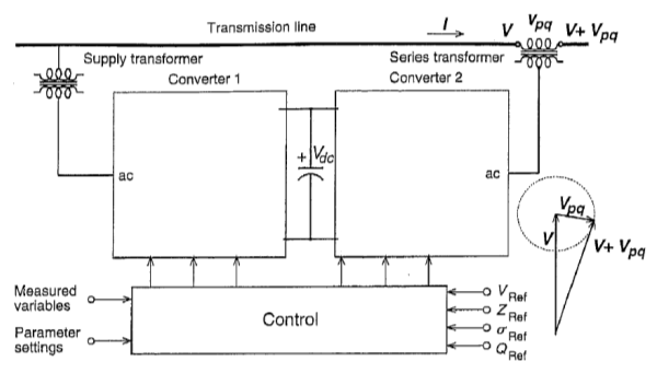
Fig.(b) UPFC by using two back to back voltage source converters.
In the figure shown below UPFC consists of two voltage source converters. This back to back converters, labelled as converter 1 and converter 2 in figure, are operated from a common DC link provided by a DC storage capacitor. This arrangement functions as an ideal AC to AC power converter in which the real power can freely flow in either direction between the AC terminals of the two converters, and each converter can independently generate or absorb reactive power at its own AC output terminal.
Converter 2 provides the main function of UPFC (by injecting a voltage Vpq with controllable magnitude Vpq) in series with the line wire and insertion transformer. This injected voltage acts essentially as a synchronous AC voltage source. The transmission line current flows through this voltage source resulting in the reactive and real power exchange between IT and the AC system. The reactive power exchanged at the terminal is generated internally by the converter. The real power exchange at ac terminal is converted into DC power which appears at the DC link as positive or negative real power demand.
Reference & Text Books
- “Modern power System Analysis”, By I J Nagrath, D P Kothari
- “Power System Analysis and Design”, By B R Gupta
- “Power System Stability and Control” By P. Kundur
- “Reactive Power Control” By T J E Miller
- “Power system analysis operation and control “By Abhijit Chakrabarti and Sunita Halder
Note: Author of this content has taken all the figures and diagrams from above reference and textbooks mentioned above to make the notes more accurate and universal.