UNIT 5
Economic Load Dispatch and Unit Commitment
Part A Economic load dispatch
The optimal system operation, in general, involved the consideration economy of operation, system security, emissions at certain fossil-fuel plants,
Optimal releases of water at hydro generation, etc. All these considerations may make for conflicting requirements and usually a compromise has to be made for optimal system operation.
The economy of operation is also called the economic dispatch problem.
The main aim in the economic dispatch problem is to minimize the total cost
Of generating real power (production cost) at various stations while satisfying
The loads and the losses in the transmission links.
A typical boiler-turbine-generator unit is sketched in Figure 1. This unit consists of a single boiler that generates steam to drive a single turbine-generator set.
H = Btu per hour heat input to the unit (or M Btu/h)
F = Fuel cost times H is the R per hour (R/h) input to the unit for fuel.
The output of the generation unit will be designated by P, the megawatt net output of the unit.
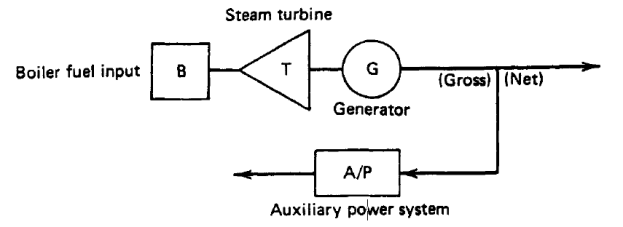
Fig. 1 A typical boiler-turbine-generator unit
Occasionally the R per hour operating cost rate of a unit will include prorated operation and maintenance costs. That is, the labour cost for the operating crew will be included as part of the operating cost if this cost can be expressed directly as a function of the output of the unit. The output of the generation unit will be designated by P, the megawatt net output of the unit.
The input-output curve of a unit can be expressed in a million kilocalories per hour or directly in terms of rupees per hour versus output in megawatts. The cost curve can be determined experimentally.
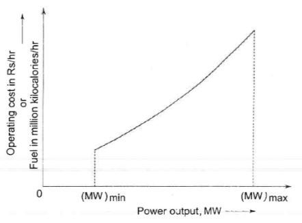
Fig.2 Input-output curve of a generating unit
A typical curve is shown in Figure 2, where (MW)min is the minimum loading limit below which it is uneconomical (or may be technically infeasible) to operate the unit and (MW)max is the maximum output limit. The input-output curve has discontinuities at steam valve openings which have not been indicated in the figure. By fitting a suitable degree polynomial, an analytical expression for operating cost can be written as
Ci(PGi) Rs/hour at output PGi
Where the suffix i stands for the unit number. It generally suffices to fit a second-degree polynomial, i.e.
 Rs/ Hour (1)
The slope of the cost curve i.e.
 is called the incremental fuel cost (lC), and is expressed in units of rupees per mega-watt-hour (Rs/KWh). A typical plot of incremental fuel cost versus power output is shown in Fig. 3
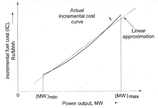
Fig.3 Incremental fuel cost versus power output for the unit whose input-output crve is shown in Fig.2.
If the cost curve is approximated as a quadratic as in Eq.1, we have
 (2)
(2)
i.e. a linear relationship. For better accuracy incremental fuel cost may be expressed by a number of short line segments (piecewise lionization). Alternatively, we can fit a polynomial of suitable degree of represent IC curve in the inverse form
 (3)
(3)
Cost Curve of Hydroelectric Units:
Hydroelectric units have input-output characteristics similar to steam turbine units. The input is in terms of volume of water per unit time; the output is in terms of electrical power. Figure 4 shows a typical input-output curve for hydroelectric plant where the net hydraulic head is constant. This characteristic shows an almost linear curve of input water volume requirements per unit time as a function of power output as the power output increases from minimum to rated load. Above this point, the volume requirements increase as the efficiency of the unit falls off. The incremental water rate characteristics are shown in Figure 5. The units shown on both these curves are English units. That is, volume is shown as acre-feet (an acre of water a foot deep). If necessary, net hydraulic heads are shown in feet. Metric units are also used, as are thousands of cubic feet per second (kft3/sec) for the water rate.
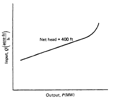
Fig. 4 Hydroelectric unit input-output curve.
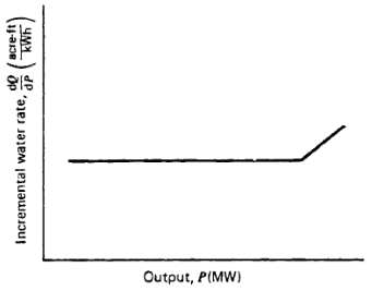
Fig. 5 Incremental water rate curve for hydroelectric plant.
At the plant level, several operating procedures were adopted in the past leading to efficient operation resulting in economy
(i) Base loading to capacity:
The turbo generators are successively loaded to their rated capacities in the order of their efficiencies. That is to say, that the most efficient unit will get greater share in load allocation which is a natural solution to the problem.
(ii) Base loading to most efficient load:
In this case the heat rate characteristics are considered and the turbo-generator units are successively loaded to their most efficient loads in increasing order of their heat rates. In both the above methods thermodynamic considerations assumed importance and the schedules will not differ from each other much.
(iii) Proportional loading to capacity:
A third method that was considered as a thumb rule in the absence of any technical data is to load the generating units in proportion to their rated capacities as stated on the name plates.
Method of Lagrange multipliers:
For a given load to be allocated between several generating units, the most efficient unit identified by incremental cost of production should be the one to get priority. When this is applied repeatedly to all the units the load allocation will become complete when all of them, that are involved in operation, are all working at the same incremental cost of production.
The above can be proved mathematically as follows:
Consider ng generating units supplying P1, P2 ............ Png active powers to supply a total load demand PD.
The objective function for minimization is the total input to the system in rupees per hour.
 (4)
(4)
Where C1(P1) is the generation cost for the ith unit and ng is the total number of generating units.
The equality constraint is given by
 (5)
(5)
i.e., total supply = total demand neglecting losses and reserve. Using the method of Lagrange multipliers for equality constraints. The Lagrange function is defined as
 (6)
(6)
Where λ is a Lagrange multiplier.
The necessary conditions are given by
 , and (7)
 (8)
(8)
 (9)
(9)
 (10)
(10)
 (11)
(11)
The later equation is the load demand constraint only; while the former gives,
 (12)
(12)
The above equation states that at the optimum all the generating stations operate at the same incremental cost for optimum economy and their incremental production cost is equal to the Lagrange multiplier λ at the optimum.
Equation (11) gives,
 (13)
(13)
The aim behind this mathematical treatment is that load should be taken up always at the lowest incremental cost. It must be ensured that the generations so determined are within their capacities. Otherwise, the generation has to be kept constant at the capacity limit for that unit and eliminated from further optimum calculations.
It can be seen that in this method at the optimum the incremental cost of production is also the incremental cost of the power received. Eqn. (12) and (13) can be solved for economic scheduling analytically neglecting the effect of transmission losses.
Simplified procedure for the derivation of the B-coefficients:
Consider a power system supplying n1 loads. Let the load currents be iL1 iL2........iLnl. These loads are supplied by ng generators. Let the generator currents be igl......ig2,····· .. igng. This is shown in the Fig.6
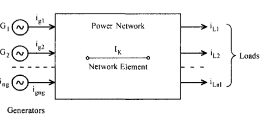
Fig. 6 Power system with generator and load currents
Consider a network element K (an inter connected line in the system) carrying current IK. Let generator I al
One supply the entire load current IL where

 (14)
(14)
Under this condition let the current in K be iKI
In a similar manner if each of the ng generators operating alone also supply the total load current IL while the rest of the generators are disconnected the current carried by the network element K changes from iKI to iK2, iK3 to iKng.
Let the ratio of iKI to iL be dK1
 (15)
(15)
Also,  and so on...
Now, if all the generators are connected to the power system simultaneously to supply the same load, by the principle of super position.
 (16)
(16)
Let the individual load currents remain a constant complex ratio of the total load current IL It is assumed that (X/R) ratio for all the line elements or branches in the network remains the same. The factors dK1 will then be real and not complex.
The individual generator currents may have phase angles δ1, δ2......δng with respect to a reference axis. The generator currents can be expressed as:

 (17)
(17)
. . .
. . .
. . .
. . .

For simplicity to derive the formula
Let ng = 3 so that eqn. (16) becomes
 (18)
(18)
 (19)
(19)
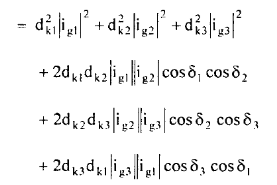 (20)
(20)
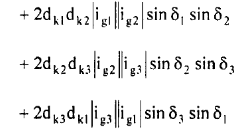
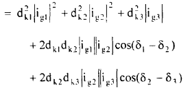 (21)
(21)

Eliminating currents in terms of powers supplied by the generators
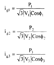
Where P1, P2 and P3 are the active power supplied by the generators 1,2 and 3 at voltages |V1|, |V2| and |V3| and power factors at the generator buses being COS 𝝓1, COS 𝝓2 and Cos 𝝓3 respectively.
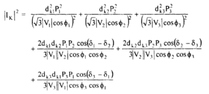
The power losses in the network comprising of nb network elements or branches PLOSS is given by

Where RK is the resistance of the element K.
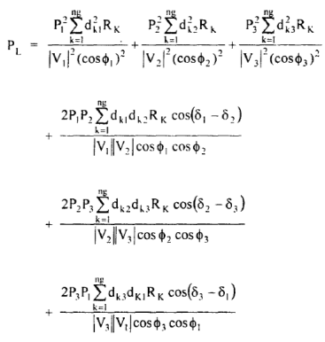 (22)
(22)
Let,
 (23)
(23)
 (24)
(24)
 (25)
(25)
 (26)
(26)
 (27)
(27)
 (28)
(28)
 (29)
(29)

In general, the formula for Bmn coefficients can be expressed as
 (30)
(30)
In the matrix form, the loss formula is expressed for an n generator system as:
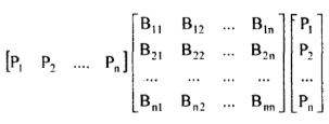 (31)
(31)
The coefficients can be considered constant, if in addition to the assumptions already made, further assume that the generator voltages V1, V2 ....... Etc remain constant in magnitude and generator bus power factors cos 𝝓1, COS 𝝓2 ....... Also remains constant.
The objective function is
 (32)
(32)
Which has to be minimized over a given period of time. As only active power is scheduled the equality constraint G(P) is given by.
 (33)
(33)
Must be satisfied at every generator bus where PI is the generation at bus i ; P D' the total load demand and PL the total transmission loss in all the lines. It is desired to minimize eqn. (32) subject to the constraint eqn. (33).
The Lagrange function L is formed as
 (34)
(34)
Applying the necessary conditions for the minimum of L
 (35)
(35)
 (36)
(36)
 (37)
(37)
 (38)
(38)
Also, it can be expressed as
 (39)
(39)
The sum of the incremental production cost of power at any plant i and the incremental transmission losses incurred due to generation P1 at bus i charged at the rate of λ must be constant for all generators and equal to λ. This constant λ is equal to the incremental cost of the received power.
The loss formula is
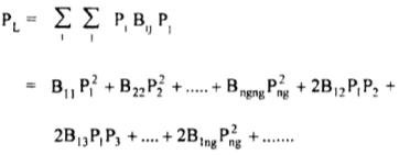 (40)
(40)
Differentiating
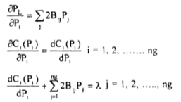 (41)
(41)
If the incremental costs are represented by a linear relationship following a quadratic input-output characteristic.
Then, denoting
 (42)
(42)
Then Equation (41) becomes
 (43)
(43)

Eqn. (42) can be rewritten as

Solving for P1
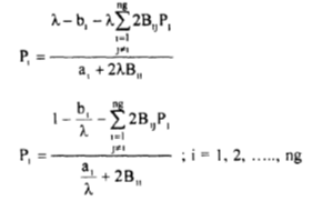
There are ng equations to be solved for ng powers (P1) for which Gauss's or Gauss - Seidel method is well suited. Knowing a1, bl, and BIJ coefficients for any assumed value of λ, PI values may converge to a solution, giving the generator scheduled powers. It is very important that a suitable value is assumed for λ, so that a quick convergence of the equations is obtained.
Consider the eqn.

It can be written as,

 (44)
(44)
When transmission losses are included, the incremental production cost at each plant i, must be multiplied by a factor
 which then will be equal to the incremental cost of power delivered. Hence, the factor
 is called penalty factor:
Since  Is much less than unity sometimes It is approximated by..
 so that,

The term
 is called approximate penalty factor.
The partial derivative) is referred to as the incremental transmission loss (ITL), Associated with the ith generating plant.
Equation (44) can also be written in the alternative form

This equation is referred to as the exact coordination equation
SLDC Activities is broadly categorized: -(A) Real-time Functions (B) Pro-active Functions.
The SLDC shall have to carry out their functions in compliance with provisions in the implemented State Electricity Grid Code and Indian Electricity Grid Code (as State Grid code has not come into force). The explanation below is intended only for general guidance of SLDC from the perspective of Availability Tariff for Central stations and Indian Electricity Grid Code (IEGC).
SLDC has to look into the daily scheduling process for Central stations. How MeECL can take advantage of the commercial mechanism now available, to trade/swap/bilateral agreement the surplus/deficit generation in certain periods of a day/season. For daily scheduling, these mainly deal with actions on the previous day, up to issuance of final schedules by RLDC.
As a general rule, the SLDC should requisition their entire entitlement in the available Central generating station capacity (other than liquid fired) for the whole day, unless their consumer load profile and intra-State generation mix is such that the total State load during certain hours of the day is expected to be less than the Central
Entitlement plus intra-State generation of a variable cost lower than the highest energy charge rate of Central generation. In such a case, the requisition from Central stations having high energy charge rates could be suitably curtailed during the concerned hours, provided the frequency is expected to rise during those hours to a level that causes the UI rate to fall below the energy charge rate of the concerned station. In case frequency is not expected to rise to such a level during those hours, Central station requisition should not be curtailed, and the surplus should be traded bilaterally or as UI (Unscheduled Interchange).
On the day of operation, the SLDC have to primarily monitor the intra-State system. They have to keep a general watch on the actual net drawal of the State from the regional grid vis-à-vis the State’s net drawal schedule, but it is not necessary to endeavour to equalize the two. In fact, in the system in place, it is beneficial as well as desirable to deviate from the net drawal schedule depending on the circumstances. For example, an overdrawal may result from increase in consumer load or reduction of intra -State generation. If there is no transmission constraint and grid frequency is good, it causes no problem for the larger grid, and the extra energy comes to the State at a low UI rate. There can be no objection to extra consumer demand being met through such overdrawal. There can also be no objection to the over-drawn energy replacing the intra State generation of a higher variable cost. The SLDC should in fact try to increase its overdrawal further, as long as frequency is good, by (i) reducing own generation which has a variable cost higher than prevailing UI rate, and (ii) restoring consumer load that had been shed.
Even if a State overdraws in a low-frequency situation, it would mean meeting consumer demand which would not have been met otherwise, and is beneficial from this angle. However, it has following adverse implications:
i) The regional grid may be endangered if frequency falls below 49.20 Hz, or if some transmission element gets excessively overloaded. RLDC may then ask the SLDC to curtail its overdrawal, and SLDC must take necessary action immediately as violation falls under IE Act 2003.
Ii) Another State (which is under-drawing) may be perceived to be getting deprived of its rightful share. However, this would be the case only if that State has resorted to load shedding, AND frequency is below 49.20 Hz. If a State carries out load shedding and thereby causes inconvenience to its consumers while frequency is above
49.20 Hz, it would be doing so either because of a misconception or for commercial reasons, i.e., to get UI payment, and therefore would not have a valid ground for feeling aggrieved.
Iii) The over-drawing State shall have to pay UI charges at a high rate. The SLDC would have to be sure that it is in the State’s overall interest. The SLDC should therefore take the following corrective action in the event of overdrawal during low frequency situation:
i) Increase Central station requisition to full entitlement (in case not fully requisitioned earlier).
Ii) Maximize generation at intra -State stations having variable costs lower than prevailing UI rate. (This can be in the form of standing instructions, i.e., frequency linked dispatch guidelines).
Iii) Harness captive and co-generation, to the extent available at a price lower than the prevailing UI rate.
Iv) Explore the possibility of purchasing power through a bilateral agreement.
v) Curtail consumers’ load.
A situation of under-drawal can arise in case consumers load in the State comes down in an unpredictable manner. If this happens at a time of general shortage in the regional grid (wherein frequency would be low), the under-drawal is beneficial for all, and SLDC should let it continue. For enhanced optimization, the SLDC may even resort to:
i) Maximizing generation at all intra-State stations whose variable cost is below the prevailing UI rate.
Ii) Increasing Central station requisition to full entitlement (in case not fully requisitioned earlier).
Iii) Harnessing captive and co-generation, to the extent available at a price lower than the prevailing UI rate.
Iv) Curtailing consumer load, by shedding low -priority consumers (provided UI earning for the utility justifies such load shedding). This is totally optional, and helps the regional grid. Overall interest of consumers in the State is however to be safeguarded by the concerned State Electricity Regulatory Commission (by specifying limits for such load shedding).
In case under-drawal takes place when grid frequency is good, the SLDC should take action to reduce the under-drawal, through one or more of the following measures:
i) Restore consumer load, which may have been shed.
Ii) Back down intra-State generation having variable costs higher than prevailing UI rate, preferably through standing frequency-linked dispatch guidelines.
Iii) May intent to reduce drawal schedules from any Central generating station whose energy charge rate is higher than the prevailing UI rate, and/or arrange a bilateral sale.
It would be seen from the above that the action to be taken by the SLDC depends on the grid frequency, rather than on whether the State is in under-drawal or over-drawal mode. The need for action on the above lines would generally arise when there is a change in system status, e.g., tripping of an intra-State generating unit, a load crash within the State, or a frequency change due to load-generation imbalance elsewhere.
Hence, the SLDC operators need to be perpetually vigilant to promptly initiate the desired action, for grid security (technical optimization) as well as commercial optimization.
Example No.1 The fuel input characteristics for two thermal plants are given by

Where P I and P 2 are in megawatts.
Obtain the economic generation schedule. The load curve is given in Fig. Below
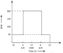
Fig. Load Curve
Solution:
For economic schedule
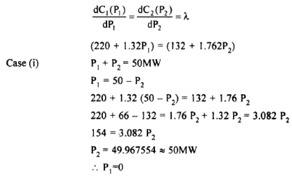
If a minimum generation limit is imposed then P1= 10MW and P2 = 40MW
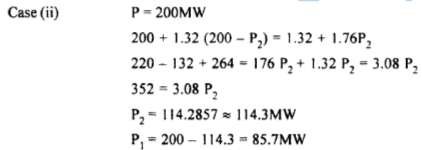
If a maximum generation limit of 100MW is imposed then

Example 2. Given a two-bus system as shown in Figure below
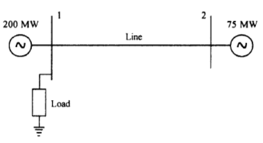
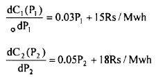
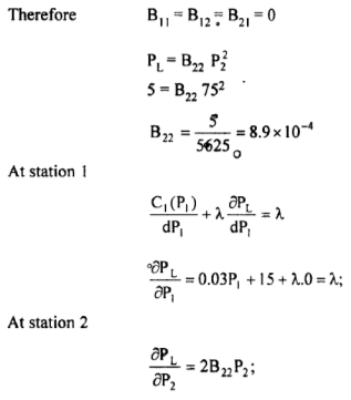
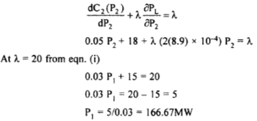
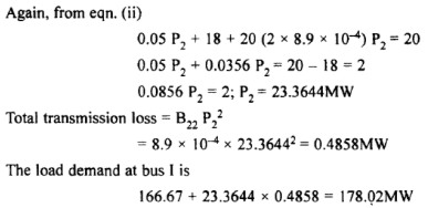
It is observed that when a power of 75MW is imported to bus 1, the loss amounted to 5MW. Find the generation needed from each plant and also the power received by the load, if the system λ. Is given by Rs.20/MWHr. The incremental fuel cost at the two plants are given by.
Solution:
The load is at bus I. Hence, P, will not have any effect on the line losses,
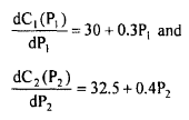
Example 3: A power system with two generating stations supplied a total load of 300MW. Neglecting transmission losses the economic schedule for the plant generation is 175MW and 125MW. Find the saving in the production cost in Rs/hr. Due to this economic schedule as compared to equal distribution of the same load between the two units. The incremental cost characteristics are
Solution:
The cost of generation at Plant 1
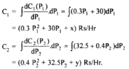
x and yare constants of integration which need not be evaluated.
For equal distribution of generation

The increase in cost at plant 1 by generating 175MW instead of 150MW is

The reduction in cost at plant 2 by generating 125MW only instead of 150MW is

Example 4: Consider two steam power plants operating with incremental production costs

Given the loss coefficients

Find the economic schedule of generation for λ = 20Rs/MWhr
Solution:
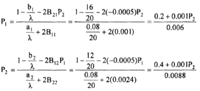
Starting with P2 = 0, P1= 33.3
Then the value of P2 is computed as 49.2
Continuing the iterations, the values obtained are tabulated
Iterations | P1 | P2 |
1 | 33.3 | 49.2 |
2 | 41.5 | 50.2 |
3 | 41.7 | 50.2 |
4 | 41.7 | 50.2 |
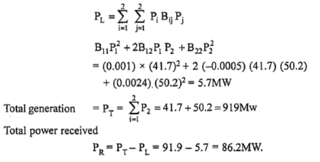
The converged values are PI = 41.7MW; and P2 = 50.2MW
With these generations, the total transmission losses are
Part B Unit commitment
The consumption of electrical energy follows a predictable daily, weekly and seasonal pattern. There are periods of high power consumption as well as low power consumption. It is therefore possible to commit the generating units from the available capacity into service to meet the demand. The previous discussions all deal with the computational aspects for allocating load to a plant in the most economical manner. For a given combination of plants the determination of optimal combination of plants for operation at any one time is also desired for carrying out the aforesaid task. The plant commitment and unit ordering schedules extend the period of optimization from a few minutes to several hours. From daily schedules weekly patterns can be developed. Likewise, monthly, seasonal and annual schedules can be prepared taking into consideration the repetitive nature of the load demand and seasonal variations. Unit commitment schedules are thus required for economically committing the units in plants to service with the time at which individual units should be taken out from or returned to service.
Many constraints can be placed on the unit commitment problem. The list presented here is by no means exhaustive. Each individual power system, power pool, reliability council, and so forth, may impose different rules on the scheduling of units, depending on the generation makeup, load-curve characteristics, and such.
i) Spinning Reserve:
Spinning reserve is the term used to describe the total amount of generation available from all units synchronized (i.e., spinning) on the system, minus the present load and losses being supplied. Spinning reserve must be carried so that the loss of one or more units does not cause too far a drop in system frequency. Quite simply, if one unit is lost, there must be ample reserve on the other units to make up for the loss in a specified time period.
Spinning reserve must be allocated to obey certain rules, usually set by regional reliability councils (in the United States) that specify how the reserve is to be allocated to various units. Typical rules specify that reserve must be a given percentage of forecasted peak demand, or that reserve must be capable of making up the loss of the most heavily loaded unit in a given period of time. Others calculate reserve requirements as a function of the probability of not having sufficient generation to meet the load.
Not only must the reserve be sufficient to make up for a generation-unit failure, but the reserves must be allocated among fast-responding units and slow-responding units. This allows the automatic generation control system to restore frequency and interchange quickly in the event of a generating-unit outage.
Beyond spinning reserve, the unit commitment problem may involve various classes of “scheduled reserves” or “off-line” reserves. These include quick-start diesel or gas-turbine units as well as most hydro-units and pumped-storage hydro-units that can be brought on-line, synchronized, and brought up to full capacity quickly. As such, these units can be “counted” in the overall reserve assessment, as long as their time to come up to full capacity is taken into account.
Reserves, finally, must be spread around the power system to avoid transmission system limitations (often called “bottling” of reserves) and to allow various parts of the system to run as “islands,” should they become electrically disconnected.
Ii) Thermal Unit Constraints:
Thermal units usually require a crew to operate them, especially when turned on and turned off. A thermal unit can undergo only gradual temperature changes, and this translates into a time period of some hours required to bring the unit on-line. As a result of such restrictions in the operation of a thermal plant, various constraints arise, such as:
Minimum up time: once the unit is running, it should not be turned off
Minimum down time: once the unit is decommitted, there is a minimum immediately. Time before it can be recommitted.
Crew constraints: if a plant consists of two or more units, they cannot both be turned on at the same time since there are not enough crew members to attend both units while starting up.
Addition, because the temperature and pressure of the thermal unit must be moved slowly, a certain amount of energy must be expended to bring the unit on-line. This energy does not result in any MW generation from the unit and is brought into the unit commitment problem as a start-up cost.
 The start-up cost can vary from a maximum “cold-start” value to a much smaller value if the unit was only turned off recently and is still relatively close to operating temperature. There are two approaches to treating a thermal unit during its down period. The first allows the unit’s boiler to cool down and then heat back up to operating temperature in time for a scheduled turn on. The second (called banking) requires that sufficient energy be input to the boiler to just maintain operating temperature. The costs for the two can be compared so that, if possible, the best approach (cooling or banking) can be chosen.
Start-up cost when cooling =
Where,
Cc= Cold start cost (MBtu)
F= Fuel cost
Cf= Fixed cost
α = Thermal time constant for the unit
t= time (h) the unit was cooled
Start-up cost when banking = Ct * t * f + Cf
Where,
Ct = cost (MBtu/h) of maintaining unit at operating temperature
Up to a certain number of hours, the cost of banking will be less than the cost of cooling.
Finally, the capacity limits of thermal units may change frequently, due to maintenance or unscheduled outages of various equipment in the plant; this must also be taken into account in unit commitment.
Iii) Other Constraints
Hydro-Constraints:
Unit commitment cannot be completely separated from the scheduling of hydro-units. In this text, we will assume that the hydrothermal scheduling (or “coordination”) problem can be separated from the unit commitment problem. We, of course, cannot assert flatly that our treatment in this fashion will always result in an optimal solution.
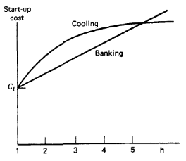
Fig. Time-dependent start-up costs.
Must Run:
Some units are given a must-run status during certain times of the year for reason of voltage support on the transmission network or for such purposes as supply of steam for uses outside the steam plant itself.
Fuel Constraints:
We will treat the “fuel scheduling” problem briefly in Chapter 6. A system in which some units have limited fuel, or else have constraints that require them to burn a specified amount of fuel in a given time, presents a most challenging unit commitment problem.
The commitment problem can be very difficult. As a theoretical exercise, let us
Postulate the following situation.
- We must establish a loading pattern for M periods.
- We have N units to commit and dispatch.
- The M load levels and operating limits on the N units are such that any one unit can supply the individual loads and that any combination of units can also supply the loads.
The real practical barrier in the optimized unit commitment problem is the high dimensionality of the possible solution space.
The most talked-about techniques for the solution of the unit commitment problem are:
1) Priority-list schemes
2) Dynamic programming (DP)
3) Lagrange relation (LR)
1) Priority-list schemes:
In this method full load average production cost is computed for every unit. Then in the order of ascending costs, the units are arranged for commitment. The method will be explained through an example. Consider three thermal plants operating with the following incremental fuel rate characteristics.
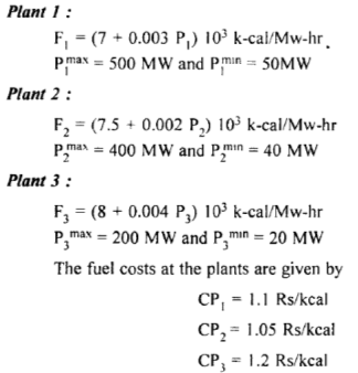
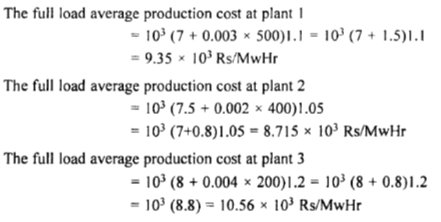
In the order of increasing costs the following table is constructed.
Unit | Rs/MwHr | Max(MW) | Min(MW) |
1 | 8.715 x 10³ | 400 | 40 |
2 | 9.35 X 10³ | 500 | 50 |
3 | 10.56 x 10³ | 200 | 20 |
The priority list for supplying a load upto 1000 Mw is prepared as follows which is self-explanatory.
Unit | Max(MW) | Min(MW) |
1 | 100 | 110 |
2 | 900 | 90 |
3 | 400 | 40 |
Table: Priority list for supply of 100 MW
The general procedure can be then staled as.
I. Check at the end of every hour of operation. If the load demand has fallen. If the demand has decreased check if the last unit in the priority list is dropped, the load demand can be met, satisfying the spinning reserve requirement. Status quo is maintained if the demand cannot be met.
2. If it is possible to drop the unit in step I, then determine the number of hours '"h" before the unit is required again for service. If this "h" is less than the shut down and start up times for the unit, it has to be left in service without removal.
3. Then, calculate the cost of floating the unit within the system without supplying any generation and the cost of shut down and start up processes and if there is sufficient savings from shutting it down, and starting it again for service it can be removed.
4. The process is to be n:peated for the next unit on the priority list and continued.
2) Dynamic Programming:
In a practical problem, the UC table is to be arrived at for the complete load cycle. If the load is assumed to increase in small but finite size steps in dynamic programming can be used to advantage for computing the UC table, wherein it is not necessary to solve the coordination equations; while at the same time the unit combinations to be tried are much reduced in number.
The total number of units available their individual cost characteristics and the load cycle on the station are assumed to be known a priori. Further, it shall be assumed that the load on each unit of combination of units changes in suitably small but uniform steps of size △MW (e.g. 1 MW).
Starting arbitrarily with any two units, the most economical combination is determined for all the discrete load levels of the combined output of the two units. At each load level the most economic answer may be to run either unit or both units with a certain load sharing between the two. The most economical cost curve in discrete form for the two units thus obtained, can be viewed as the cost curve of a single equivalent unit. The third unit is now added and the procedure repeated to find the cost curve of the three combined units. It may be noted that in this procedure the operating combinations of third and first, also third and second are not required to be worked out resulting in considerable saving in computational effort. The process is repeated, till all available units are exhausted. The advantage of this approach is that having obtained the optimal way, of loading ft units, it is quite easy to determine the optimal manner of loading (K + 1) units.
Let a cost function FN (x) be defined as follows:
FN (x) = the minimum cost in Rs/hr of generating x MW by N units
FN (y) = cost of generating y MW by the Nth unit
FN (N- y) - the minimum cost of generating (x - y) Mw by the remaining (N- 1) units.
Now the application of DP results in the following recursive relation

Using the above recursive relation, we can easily determine the combination of units, yielding minimum operating costs for loads ranging in convenient steps from the minimum permissible load of the smallest unit to the sum of the capacities of all units. In this process the total minimum operating cost and the load shared by each unit of the optimal combination are automatically determined for each load level.
The use of DP for solving the UC problem is illustrated by means of an example:
Consider a sample system having four thermal generating units with parameters listed in Table below. It is required to determine the most-economical units to be committed for a load of 9 MW. Let the load changes be in steps of I MW.
Unit No. | Capacity (MW) | Cost curve parameters (d = 0) | ||
Min | Max | a Rs/ MW2 | b Rs/ MW | |
1 | 1.0 | 12 | 0.77 | 23.5 |
2 | 1.0 | 12 | 1.60 | 26.5 |
3 | 1.0 | 12 | 2.00 | 30.0 |
4 | 1.0 | 12 | 2.50 | 32.0 |
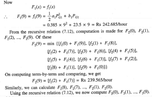

Examination of F1(9), F2(9), F3(9) and F4(9) leads to the conclusion that optimum units to be committed for a 9 MW load are 1 and 2 sharing the load as 7MW and 2 MW, respectively with a minimum operating cost of Rs 239.565/hour.
It must be pointed out here, that the optimal UC table is inexpedient of the numbering of units, which could be completely arbitrary.
3) Lagrange relation (LR):
The dynamic-programming method of solution of the unit commitment problem has many disadvantages for large power systems with many generating units. This is because of the necessity of forcing the dynamic-programming solution to search over a small number of commitment states to reduce the number of combinations that must be tested in each time period.
In the Lagrange relaxation technique these disadvantages disappear. This method is based on a dual optimization approach.
Defining the variable  as:
as:
 = 0 if unit i is off-line during period t
 = 1 if unit i is on-line during period t
We shall now define several constraints and the objective function of the unit commitment problem:
- Loading constraints:

2. Unit limits:

3. Unit minimum up- and down-time constraints. Note that other constraints can easily be formulated and added to the unit commitment problem. These include transmission security constraints, generator fuel limit constraints, and system air quality constraints in the form of limits on emissions from fossil-fired plants, spinning reserve constraints, etc.
4. The objective function is:

We can then form the Lagrange function similar to the way we did in the economic dispatch problem:

The unit commitment problem requires that we minimize the Lagrange function above, subject to the local unit constraints 2 and 3, which can be applied to each unit separately. Note:
- The cost function, F(
 ), together with constraints 2 and 3 are each separable over units. That is, what is done with one unit does not affect the cost of running another unit, as far as the cost function and the unit limits (constraint 2) and the unit up- and down-time (constraint 3) are concerned.
 - Constraints 1 are coupling constraints across the units so that what we do to one unit affects what will happen on other units if the coupling constraints are to be met.
The Lagrange relaxation procedure solves the unit commitment problem by “relaxing” or temporarily ignoring the coupling constraints and solving the problem as if they did not exist. This is done through the dual optimization procedure as explained in the appendix of this chapter. The dual procedure attempts to reach the constrained optimum by maximizing the Lagrangian with respect to the Lagrange multipliers, while minimizing with respect to the other variables in the problem; that is:

Where,

This is done in two basic steps:
Step 1: Find a value for each λ‘, which moves q(λ) toward a larger value.
Step 1: Assuming that the λ‘ found in step 1 are now fixed, find the minimum of Y by adjusting the values of Pt and Ut.
The adjustment of the λ’, values will be dealt with at a later time in this section; assume then that a value has been chosen for all the λ‘ and that they are now to be treated as fixed numbers. We shall minimize the Lagrangian as follows. First, we rewrite the Lagrangian as:

The second term above is constant and can be dropped (since the I' are fixed). Finally, we write the Lagrange function as:

Here, we have achieved our goal of separating the units from one another. The term inside the outer brackets; that is:

Can be solved separately for each generating unit, without regard for what is happening on the other generating units. The minimum of the Lagrangian is found by solving for the minimum for each generating unit over all time periods; that is:

And the up- and down-time constraints. This is easily solved as a dynamic programming problem in one variable. This can be visualized in the figure
Below, which shows the only two possible states for unit i (i.e., U: = 0 or 1):

Where Si is the start-up cost of the Unit i.
At the  state, the value of the function to minimise the trivial (i.e. it is equal to zero) at the state where
  , the function to be minimised is (the start-up cost is dropped here since the minimization is with respect to
  ).
).

The minimum of this function is found by taking the first derivative:

The solution to this equation is

There are three cases to be concerned with depending on the relation of  and the unit limits:
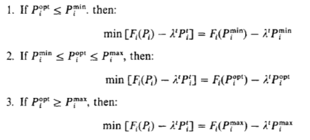
The solution of the two-state dynamic program for each unit proceeds in the normal manner as was done for the forward dynamic-programming solution of the unit commitment problem itself. Note that since we seek to minimize[ at each stage and that when
  this value goes to zero, then the only way to get a value lower is to have
[
The dynamic program should take into account all the start-up costs, Si, for each unit, as well as the minimum up and down time for the generator. Since we are solving for each generator independently, however, we have avoided the dimensionality problems that affect the dynamic-programming solution.
Many of the Lagrange relaxation unit commitment programs use a few iterations of a dynamic-programming algorithm to get a good starting point, then run the dual optimization iterations, and finally, at the end, they use heuristic logic or restricted dynamic programming to get to a final solution. The result is a solution that is not limited to search windows, such as had to be done in strict application of dynamic programming.