Unit 1
Electrical Drives
Electrical drives mainly accomplishes three kinds of work,
- Starting
- Speed control
- Braking
They enable us to control the motor in every aspect.
But controlling them is also necessary because all the functions accomplished by the drives are mainly transient operations.
- Highly efficient.
- Low maintenance requirements due to absence of moving parts.
- Better adhesion.
- Higher acceleration, deceleration and speed due to better adhesion.
- Increased comfort of passengers due to smooth acceleration and braking.
- Easy maintenance, repair and fault diagnosis.
- Longer life.
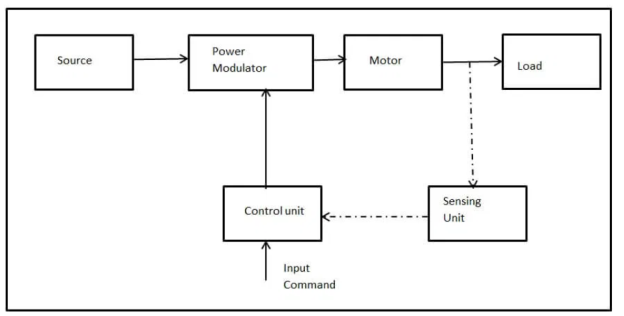
The electric drive system has five main functional blocks namely a power source, Power Modulator (Converter), a motor, a mechanical load and a controller(which incorporates sensing unit and control unit).
- The power source provides the required energy to the electric drive system. The converter interfaces the motor with the power source and provides the motor with adjustable voltage, current and frequency.
- The controller monitors the operation of the entire system and ensures the overall system performance and stability. The ratings of mechanical load and type of power source are not in our decision.
- The mechanical loads are determined by the nature of the industrial operation and the power source is determined by what is available at the site. But we can select the other components like electric motor, converter and controller.
- The function of converters is to convert the electric waveform of the power source to a waveform that the motor can use. For example the available power source is AC and the motor is DC series motor, then the converter converts ac into dc. In other words a rectifier circuit is placed in the system.
- The motor for the particular application is selected by considering various factors like cost, meeting the power level and performance required by the load during steady state and dynamic operations.
AC Drive
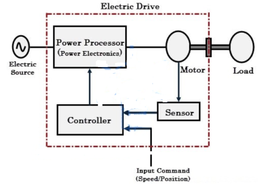
The electric motor is the core component of an electrical drive that converts electrical energy (directed by power processor) into mechanical energy (that drives the load). The motor can be DC motor or AC motor depends on the type of load.
The controller tells the power processor, how much power it has to generate by providing the reference signal to it after considering the input command and sensor inputs. The controller could be a microcontroller, a microprocessor, or a DSP processor.
A variable speed drive used to control DC motors are known as DC drives and the variable speed drives used to control AC motors are called as AC drives. In this article we are going to discuss about the AC drives.
Components:
Classification of AC Drives
AC drives are used to drive the AC motor especially three phase induction motors because these are predominant over other motors in most of the industries. In industrial terms, AC drive is also called as variable frequency drive (VFD), variable speed drive (VSD), or adjustable speed drive (ASD).
DC Drive
DC drive is basically a DC motor speed control system that supplies the voltage to the motor to operate at desired speed. Earlier, the variable DC voltage for the speed control of an industrial DC motor was generated by a DC generator.
Components:
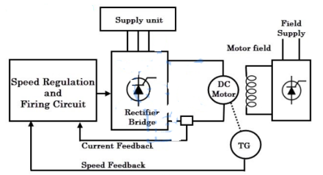
- DC Drive Input: Some thyristor based DC drives operate on a single phase supply and use four thyristors for full wave rectification. For larger motors, three phase power supply is needed because the waveforms are much smoother. In such cases, six thyristors are needed for full wave rectification.
- Rectifier Bridge: The power component of a controlled DC drive is a full wave bridge rectifier which can be driven by three phase or single phase supply. As mentioned above the number of thyristor may vary depends on the supply voltage.
- Field Supply Unit: The power to be applied to the field winding is much lower than the armature power, so, most often single phase supply is provided. A separate thyristor bridge or diode rectifier is used for supplying the power to the field winding of the motor.
- The function of the field supply unit is to provide a constant voltage to the field winding to create a constant field or flux in the motor.
- Speed Regulation unit: It compares the operator instruction (desired speed) with feedback signals and sends appropriate signals to the firing circuit. In analog drives, this regulator unit consists of both voltage and current regulators. The voltage regulator accepts the speed error as input and produces the voltage output which is then applied to the current regulator.
- Firing Circuit: It supplies the gate pulses to thyristors so that they turned ON for particular periods to produce variable armature voltage. Isolation is also provided in this gate drive circuit.
Working
In DC motors, the speed is proportional to the armature voltage and inversely proportional to the field current. And also, the armature current is proportional to the motor torque. Therefore, by increasing or reducing the applied voltage, the speed of the motor is varied. However, it is possible up to the rated voltage. If the speed greater than the base speed is required, the field current of the motor has to be reduced.
In armature controlled DC drives, drive unit provides a rated current and torque at any speed between zero and the base of the motor. By varying the armature voltage, variable speed is obtained as shown in figure.
Generally, a fixed field supply is provided in these DC drives. As the torque is constant (which describes a load type) over the speed range, the motor output horsepower is proportional to the speed (HP = T × N / 525).
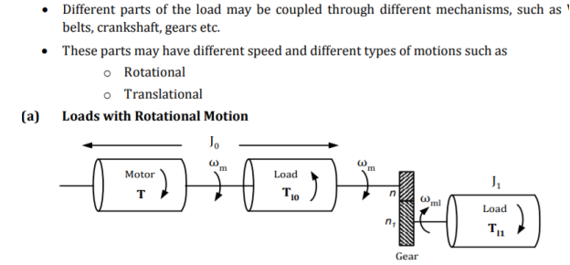
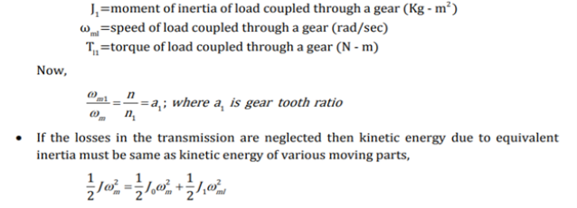
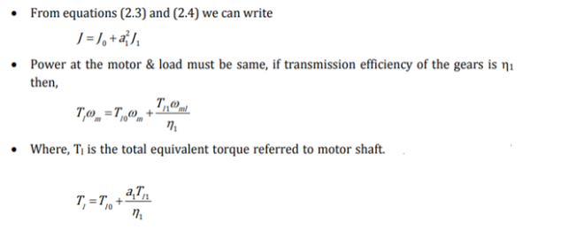
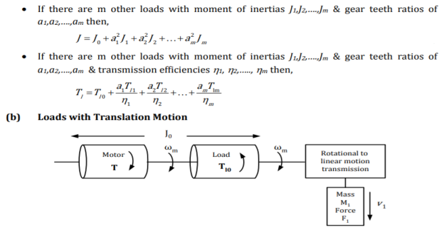
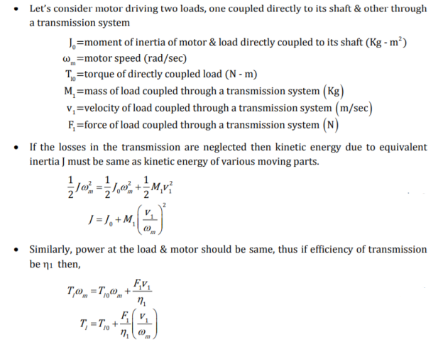
When the motor rotates, the load of the system may rotate or may go through a translational motion. In the translational motion, the position of the body changes from point to point in space. The speed of the load may be different from that of the motor.
If the load has different parts, their speed may be different. Some part of the rotor may rotate while others may go through a translational motion. The equivalent load system of the motor is shown in the figure below.

Where J – the polar moment of inertia of motor-load system, referred to the motor shaft, kg-m2
ωm – instantaneous angular velocity of the motor shaft, rad/sec.
T – the instantaneous value of developed motor torque, N-m.
T1 – the instantaneous value of load torque, referred to a motor shaft, N-m.
The equation shown below described the motor load equation.This equation is applicable for variable inertia drives such as mine, winders, reel, drives, industrial robots. In this equation, the load torque includes friction and windage torque of the motor.

For constant inertia drive dj/dt = 0. Therefore the equation becomes

The above equation shows that the load developed by the motor is counter-balanced by a load torque T1 and a dynamic torque jdωmt/dt.The torque component j(dωmt/dt) is called dynamic torque because it is present only during transient operations.
The acceleration or deceleration of the drive mainly depends on whether the load torque is greater or less than the motor torque. During acceleration, the motor supplies the load torque along with an additional torque component jdωmt/dt to overcome the drive inertia.
The drives which have a large inertia must increase the load torque by a large amount for getting sufficient acceleration. The drive which requires a fast transient response, their motor torque should be maintained at the excessive value and motor load system should be designed with a lower possible inertia.
The energy associated with dynamic torque is stored in the form of kinetic energy and given by the equation jdω2m/dt. During the deceleration, the dynamic torque has a negative sign. Thus it assists the motor developed torque T and maintains the drive motion by extracting energy from stored kinetic energy.
- A motor operate in 2 modes – Motoring and braking. In motoring, it converts electrical energy into mechanical energy which support its motion. In braking, it converts as a generator converting mechanical energy into electrical energy and thus opposes the motion. Motor can provide motoring & braking for both forward & reverse directions. Power developed by a motor is given by the product of speed & torque.
- Equilibrium speed of motor-load system can be obtained when motor torque equals the load torque. Electric drive system will operate in steady state at this speed, provided it is the speed of stable state equilibrium.
- A motor operates in two modes – Motoring and braking. In motoring, it converts electrical energy into mechanical energy, which supports its motion. In braking it works as a generator converting mechanical energy into electrical energy and thus opposes the motion.
- Motor can provide motoring and braking operations for both forward and reverse directions. Figure shows the torque and speed co-ordinates for both forward and reverse motions.
- Power developed by a motor is given by the product of speed and torque. For motoring operations power developed is positive and for braking operations power developed is negative.
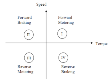
In quadrant I, developed power is positive, hence machine works as a motor supplying mechanical energy. Operation in quadrant I is therefore called Forward Motoring.
In quadrant II, power developed is negative. Hence, machine works under braking opposing the motion. Therefore operation in quadrant II is known as forward braking.
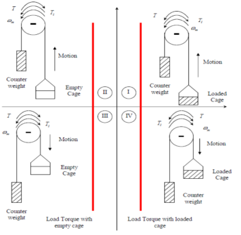
Similarly operation in quadrant III and IV can be identified as reverse motoring and reverse braking since speed in these quadrants is negative. For better understanding of the above notations, let us consider operation of hoist in four quadrants as shown in the figure. Direction of motor and load torques and direction of speed are marked by arrows.


Classification of Load Torques:
Various load torques can be classified into two broad categories
- Active Load torques:
Load torques which have the potential to drive the motor under equilibrium conditions are called active load torques. Load torques usually retain sign when the drive rotation is changed. Eg: Torque due to force of gravity Torque due tension Torque due to compression and torsion etc.
2. Passive Load torques:
Load torques which always oppose the motion and change their sign on the reversal of motion are called passive load torques Eg: Torque due to friction, cutting etc.
Components of Load Torques:
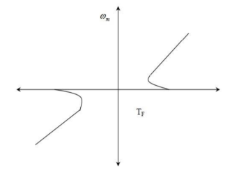
- Friction Torque (TF): Friction will be present at the motor shaft and also in various parts of the load. TF is the equivalent value of various friction torques referred to the motor shaft.
- Windage Torque (TW): When motor runs, wind generates a torque opposing the motion. This is known as windage torque.
Torque required to do useful mechanical work: Nature of this torque depends upon particular application. It may be constant and independent of speed. It may be some function of speed, it may be time invariant or time variant, its nature may also change with the load’s mode of operation. Value of friction torque with speed is shown in figure below :
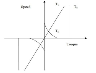
Component Tv varies linearly with speed is called VISCOUS friction and is given by

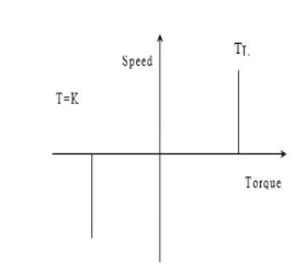
The most important need for driving a machine is the matching of speed-torque characteristics of the given drive unit and that of the motor. Different types of loads exhibit different speed torque characteristics. They are categorised as:
Constant torque type load
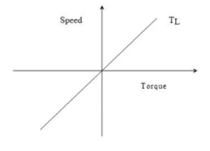
- Torque proportional to speed (Generator Type load)
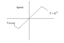
- Torque proportional to square of the speed (Fan type load)
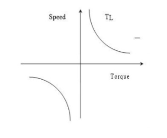
- Torque inversely proportional to speed (Constant power type load)
Constant Torque characteristics:
Many working machines have mechanical nature of work like shaping, cutting, grinding or shearing, require constant torque irrespective of speed.
Torque Proportional to speed:
Separately excited dc generators connected to a constant resistance load, eddy current brakes have speed torque characteristics given by
T=k
Torque proportional to square of the speed:
Here load torque is proportional to the square of the speed.
Examples:
ü Fans rotary pumps,
ü Compressors
ü Ship propellers
Torque Inversely proportional to speed:
The concept has been developed to evaluate the stability of an equilibrium point from the steady state speed torque curves of the motor and load system. In many electrical drives, the electrical time constant is negligible as compared with the mechanical time constant.
During transient condition, electrical motor can be assumed to be in electrical equilibrium implying that steady state speed torque curves are also applicable to the transient state operation. Now, consider the steady state equilibrium point A shown in figure below
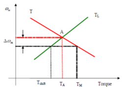
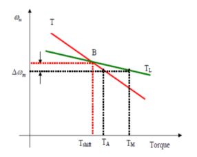
For consideration of multi quadrant operation of drives, it is useful to establish suitable conventions about the signs of torque and speed.
Example 1:
A 220V, 200 A, 800 rpm dc separately excited motor has an armature resistance of 0.06Ω.The motor armature is fed from a variable voltage source with an internal resistance of 0.04Ω. Calculate internal voltage of the variable voltage source (VVS) when the motor is operating in motoring at 50% of the rated motor torque and 400 rpm.
Sol.
We know that the motor torque, Tm is proportional to the armature current, Ia.
The motor speed, N is proportional to the back emf, E The motor armature current at 50% of the rated motor torque is
Ia = 0.5 × 200 = 100A
The back emf at the rated speed and the rated torque is
E = Va – IaRa = 220 -200 × 0.06 = 208 V
The back emf at 400 rpm is
E = 𝑁2 𝑁1 × E = 400 800 × 208 = 104 V
Internal voltage of VVS is 𝑉𝑖𝑛𝑡 = E + 𝐼𝑎 (𝑅𝑎 + 𝑅𝑖𝑛𝑡) = 104 + 100(0.06 + 0.04) = 114 𝑉. 5.
Example 2.
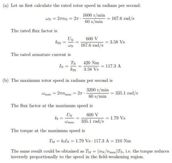
A DC motor with a separately excited field winding is considered. The rated armature voltage is UN = 600 V, rated torque TN = 420 Nm, rated speed N = 1600 r/min, and maximum speed Nmax = 3200 r/min. The losses are omitted.
(a) The flux factor kf is kept constant at its rated value. When the armature voltage is varied from 0 to UN, the speed varies from 0 to N. Determine the rated armature current IN.
(b) A load is to be driven in the speed range from N to Nmax by weakening the flux factor while the armature voltage is kept constant at UN Determine the torque available at maximum speed, if the rated armature current IN is not exceeded.
Sol. The losses are omitted, i.e., Ra = 0 holds. Hence, the steady-state equations of the DC motor are 6. Discuss voltage source inverter (VSI) fed Induction motor drive.
Reference Books
[R1] B. K. Bose, “Modern Power Electronics and AC Drives”, Pearson Education
[R2] Malcolm Barnes, “Practical Variable Speed Drives and Power Electronics”, Elsevier
Newnes Publications
[R3] V. Subrahmanyam, “Electric Drives: Concepts and Application”, Tata Mc-Graw Hill
(An imprint of Elsevier)
[R4] M.D. Singh and Khanchandani “Power Electronics”, Tata Mc-Graw Hill
[R5] Austin Huges, “Electrical motor and drives: Fundamental, types and applications”,
Heinemann Newnes, London
[R6] Tyagi MATLAB for engineers oxford (Indian Edition)