Unit 3
Induction motor Drives I
Dynamic breaking is to slow down the machine by converting kinetic energy to heat energy by switching the circuit from line/supply to a breaking circuit that cause motor to behave as a generator with a connected load.
There are two methods of dynamic breaking
- DC injection
- Capacitor breaking
DC injection
Cut off the motor supply and connect any two terminals with a DC injection circuit through a current limiting resistor. The DC voltage sets up a stationary magnetic field that generates a voltage in the rotor winding which is dissipated as resistive heat loss or copper loss.

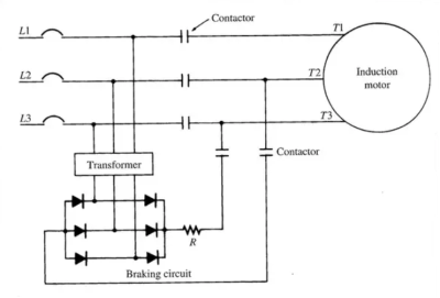
Fig: DC injection Dynamic Breaking
Capacitor Breaking
Cutoff the supply, connect a capacitor bank as shown in the figure, the motor will act as a self excited induction generator and rotational energy is dissipated as copper loss or I2R loss in the rotor and stator winding. This effect can be enhanced by adding a resistive load.

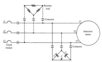
Fig: Capacitor Braking Dynamic Breaking
It is obtained when the motor is run on the single phase supply by disconnecting the one phase from the source and either leaving it open or connecting it with another phase. The two connections are respectively known as two and three lead connection.
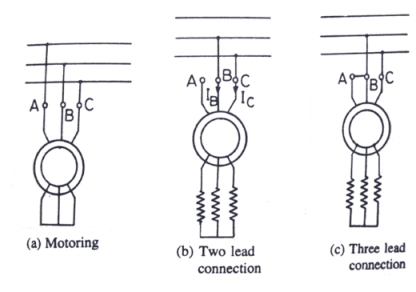
When connected to a one phase supply the motor can be considered as to be fed by positive and negative sequence three phase set of voltage. The total torque produced by the machine is the sum of torque due to positive and negative sequence voltage. When the rotor has high resistance, then the net torque is negative, and the braking operation is obtained.
Assume the phase A of the star connected motor is open circuited. Then the current flow through the phase A becomes zero, i.e., Ia = 0 and current through the other two phases is IB = – IC.
The positive and negative sequence component Ip and In are represented by the equation.

Where α = ej20°
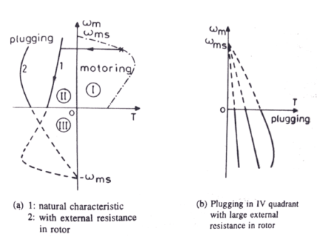
- Plugging induction motor braking is done by reversing the phase sequence of the motor.
- It is done by interchanging connections of any two phases of stator with respect of supply terminals.
- And with that the operation of motoring shifts to plugging braking.
- During plugging the slip is (2 – s), if the original slip of the running motor is s, then it can be shown in the following way.

- Here, the torque is not zero at zero speed.
- Hence, when the motor is needed to be stopped, it should be disconnected from the supply at near zero speed.
- The motor is connected to rotate in the reverse direction and the torque is not zero at zero or any other speed, and as a result the motor first decelerates to zero and then smoothly accelerates in the opposite direction.
We know the power (input) of an induction motor is given as.
Pin = 3VIscosφs
Here, φs the phase angle between stator phase voltage V and the stator phase current Is.
Now, for motoring operation φs < 90o and for braking operation φs > 90o.
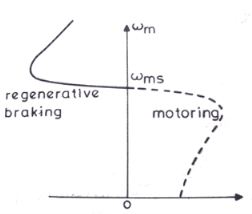
- When the speed of the motor is more than the synchronous speed, relative speed between the motor conductors and air gap rotating field reverses, as a result the phase angle because greater than 90o and the power flow reverse and thus regenerative braking takes place.
- It the source frequency is fixed then the regenerative braking of induction motor can only take place if the speed of the motor is greater than synchronous speed, but with a variable frequency source regenerative braking of induction motor can occur for speeds lower than synchronous speed.
- The main advantage of this kind of braking can be said that the generated power is use fully employed and the main disadvantage of this type of braking is that for fixed frequency sources, braking cannot happen below synchronous speeds.
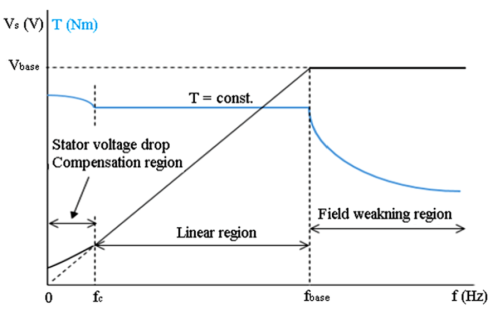
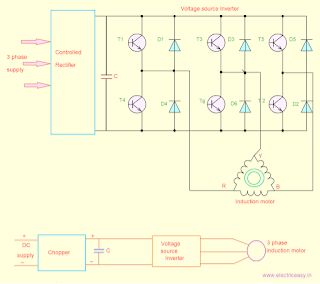
Voltage Source Inverter Control of Induction Motor allows a variable frequency supply to be obtained from a dc supply.
Fig. Shows a VSI employing transistors.
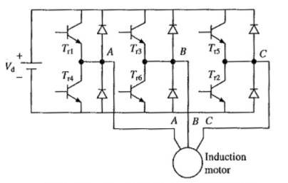

- It can be operated as a stepped wave inverter or a pulse-width modulated (PWM) inverter.
- When operated as a stepped wave inverter, transistors are switched in the sequence of their numbers with a time difference of T/6 and each transistor is kept on for the duration T/2, where T is the time period for one cycle.
- Resultant line voltage waveform is shown in Fig. Frequency of inverter operation is varied by varying T and the output voltage of the inverter is varied by varying dc input voltage.
- The current source inverter converts the input direct current into an alternating current. In this, the input current remains constant but its adjustable. It is also called current fed inverter.
- The output voltage is independent of the load. The magnitude and nature of the load current depends on the nature of load impedance.
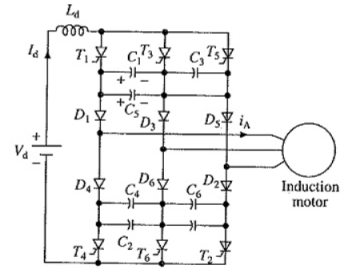
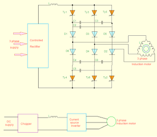
- A thyristor Current Source Inverter Control of Induction Motor (CSI) is shown in Fig.
- Diodes D1-D6 and capacitors C1-C6 provide commutation of thyristors T1-T6, which are fired with a phase difference of 60° in sequence of their numbers.
- It also shows the nature of output current waveforms. Inverter behaves as a current source due to the presence of large inductance Ld in dc link.
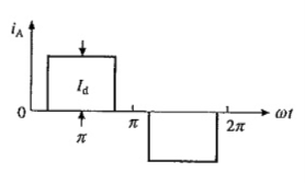
The fundamental component of motor phase current is

Open Loop:
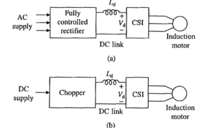
- For a given speed, torque is controlled by varying dc link current Id by changing the value of Vd.
- Therefore, when supply is ac, a controlled rectifier is connected between the supply and inverter and when supply is dc, a chopper is interposed between the supply and inverter.
- The maximum value of dc output voltage of fully-controlled rectifier and chopper are chosen so that the motor terminal voltage saturates at rated value.
Closed loop:
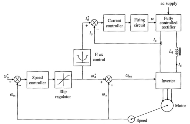
- A closed loop Current Source Inverter Control of Induction Motor drive is shown in Fig.
- Actual speed ωm is compared with the reference speed ω*m.
- The speed error is processed through a PI controller and slip regulator.
- The slip regulator sets the slip speed command ω*s1.
- The synchronous speed obtained by adding ωm ω*s1, determines the inverter frequency.
- Constant flux operation is obtained when slip speed ωs1 (or rotor frequency) and Is have relationship
- When inverter frequency is reduced to make synchronous speed less than motor speed, machine works as a generator.
- Power flows from machine to dc link and dc link voltage Vd reverses.
- If fully-controlled converter of Fig. (a) is made to work as an inverter, the power supplied to dc link will be transferred to ac supply and regenerative braking will take place,
- Thus, no additional equipment is required for regenerative braking of CSI drive of Fig. (a). Change of phase sequence of Current Source Inverter Control of Induction Motor will provide motoring and braking operations in the reverse direction.
- The drive of Fig. (b) can have regenerative braking capability and four-quadrant operation if a two quadrant chopper providing current in one direction but voltage in either direction is used.
VSI | CSI |
VSI is used to fed impressed voltages | CSI is used to fed the impressed currents |
Load commutation is not possible | Both forced and load commutations are possible |
Open loop and closed loop operations are possible | Only closed loop control is possible |
Voltage with variable frequency is fed to Induction motor | The current with variable frequency is fed to Induction motor |
The efficiency is medium | The efficiency is high |
These drives are suitable for low, medium power applications | These drives are suitable for medium and high power applications |
Multi motor operation is possible | Multi motor operation is not possible |
Pulse Width Modulation( PWM) technique is used to reduce the problems of harmonic content, torque pulsations, motor heating etc. | The PWM technique is not used in CSI so the distortions in the output are more. |
It gives good and satisfactory behavior in transient and dynamic state.
| Poor dynamic behavior
 |
1. Find motor phase current if dc link current is 10mA.
Solution:
We know

Id = 10mA
Then Is = 1.91 mA.
Reference Books
[R1] B. K. Bose, “Modern Power Electronics and AC Drives”, Pearson Education
[R2] Malcolm Barnes, “Practical Variable Speed Drives and Power Electronics”, Elsevier
Newnes Publications
[R3] V. Subrahmanyam, “Electric Drives: Concepts and Application”, Tata Mc-Graw Hill
(An imprint of Elsevier)
[R4] M.D. Singh and Khanchandani “Power Electronics”, Tata Mc-Graw Hill
[R5] Austin Huges, “Electrical motor and drives: Fundamental, types and applications”,
Heinemann Newnes, London
[R6] Tyagi MATLAB for engineers oxford (Indian Edition)