Unit 5
Synchronous motor Drives
Synchronous motor drives are used in many industrial applications. They are generally more expensive than induction motor drives, but the advantages is that the efficiency is higher, which is tends to lower the life cycle cost.
There are different types of synchronous motors based on the way they are excited
- Non Excited Synchronous Motors
The rotor is made up of steel. The external magnetic field magnetizes the rotor, and it rotates in synchronism with it. The rotor is generally made of high retentively steel such as cobalt steel.
Non-excited motors are available in three designs
- Hysteresis Motor
Hysteresis motors are single phase motors in which the rotor is made up of ferromagnetic material. The rotors are cylindrical in shape and have high hysteresis loss property. They are generally made up of chrome, cobalt steel or alnico. The stator is fed by single phase AC supply. The stator has two windings:
- Main windings and
- Auxiliary windings.
2. Reluctance Motor
The reluctance motor is based on the principle that an unrestrained piece of iron will move to complete a magnetic flux path where the reluctance is minimum. The stator has the main winding and the auxiliary windings just like the hysteresis motor. These help to create a rotating magnetic field. The rotor of a reluctance motor is a squirrel cage rotor with some teeth removed to provide the desired number of salient poles. The reluctance becomes minimum when the rotor is aligned with the magnetic field of the stator.
3. Permanent Magnet Synchronous Motors
The rotor is made up of permanent magnets. They create a constant magnetic flux. The rotor locks in synchronism when the speed is near synchronous speed. They are not self-starting and need electronically controlled variable frequency stator drive
- Current Excited Synchronous Motors
Direct current excited synchronous motors need a DC supply to the rotor to generate rotor magnetic field. A direct current excited motor has both stator windings as well as rotor windings. They can either have cylindrical rotors or salient pole rotors. They are not self-starting and need damper windings to start. Initially, they start as an induction motor and later attains synchronous speed.
The equivalent-circuit model for one armature phase of a cylindrical rotor three phase synchronous motor is shown in Fig. Exactly similar to that of a synchronous generator except that the current flows in to the armature from the supply. All values are given per phase. Applying Kirchhoff ’s voltage law to Fig. ,
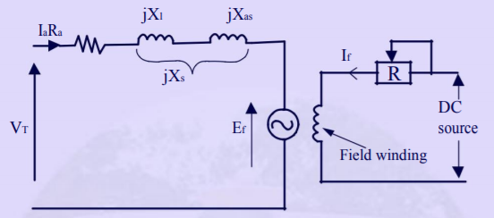
VT = IaRa + jIaXl + jIaXas + Ef
Combining reactances,
We have Xs = Xl + Xas
Substituting in Eqn.
VT = Ef + Ia(Ra + jXs) or VT = Ef + IaZs
Where: Ra = armature resistance (Ω/phase)
Xl = armature leakage reactance (Ω/phase)
Xs = synchronous reactance (Ω/phase)
Zs = synchronous impedance (Ω/phase)
VT = applied voltage/phase (V)
Ia = armature current/phase(A)
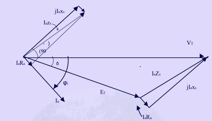
A phasor diagram shown in Fig., illustrates the method of determining the counter EMF which is obtained from the phasor equation;
Ef = VT − IaZs
The phase angle δ between the terminal voltage VT and the excitation voltage Ef in Fig. Is usually termed the torque angle. The torque angle is also called the load angle or power angle.
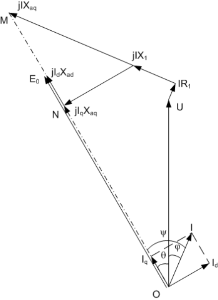
- It includes a rotor core, a plurality of pole bodies, and a field winding.
- Each pole body includes a pole core, a pole shoe, and a single flux barrier.
- The single flux barrier forms an enclosed space filled with a material having a magnetic permeability between zero and 1000 relative to a magnetic permeability of a vacuum.
- The single flux barrier includes a top wall, a shaft mounting wall configured to mount adjacent a shaft when the rotor is mounted to the shaft, and a plurality of interior walls connected between the top wall and the shaft mounting wall.
- The plurality of interior walls extend parallel to and centered between a first pole core face and a second pole core face of the pole core that extend from the rotor core.
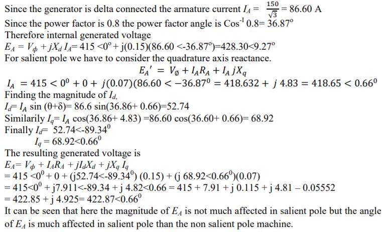
1. A 450 volt, 50 Hz, ∆ connected, 4 pole, 3-phase synchronous generator has direct axis reactance of 0.15Ω and quadrature axis reactance of 0.07Ω .Its armature resistance may be neglected. At full load the generator supplies 150A at a power factor of 0.8 lagging.
(a) Find the internal generated voltage EA of this generator at full load, assuming that it has cylindrical rotor reactance is Xd.
(b) Find the generated internal voltage EA of this generator at full load assuming that it has a salient pole rotor.
Solution
2. The following information has been obtained during the preliminary design of a 3 phase 500 kVA, 6.6 kV, 12 pole, 500 rpm, star connected salient pole alternator. Stator diameter = 1.3 m, gross length of stator = 0.21m, air gap flux per pole = 0.0404 wb Based on the above information, design the field system of the alternator giving the following details.
(i) Length of the air gap
(ii) Diameter of the rotor at the air gap surface
(iii)Dimension of the pole
Soln:
(i) Length of the air gap : Air gap flux per pole = Bav x πDL/p
= (12 x 0.0404)/( π x1.3 x 0.21)
= 0.56 Tesla
We have ATf0 = SCR x ATa and ATa=1. 35 Iph Tph Kw /p
We have Eph = 4.44 f Tph kw and
Hence Tph x Kw = Eph/(4.44f ) = 6600/√3/ ( 4.44 x 50 x 0.0404) = 424 Full load current = 500 x 103/ √3 x 6600 = 43.7 amps
ATa=1. 35 Iph Tph Kw /p = 1.35 x 43.7 x 424 /6 = 4169 AT
Assuming a short circuit ratio of 1.1 ATf0 = SCR x ATa = 1.1 x 4169 = 4586 AT Assuming AT required for the air gap as 70 % of the no load field ampere turns per pole ATg = 0.7 x ATfo = 0.7 x 4586 = 3210 AT
Assuming Carter’s coefficient for the air gap kg as 1.15 and field form factor Kf as 0.7 Bg = Bav/Kf = 0.56/0.7 = 0.8 Tesla
We have air gap ampere turns ATg = 796000 Bg kg lg
Hence air gap length lg = 3210 / ( 796000 x 0.8 x 1.15) = 0.0044 m = 4.4 mm
(ii) Diameter of the rotor Dr = D - 2 lg = 1.2 – 2 x 0.0044 = 1.191m
(iv) Peripheral speed = πDrNs / 60 = π x 1.191 x 500/60 =31.2 m/s
(v) Dimensions of the pole : Assuming the axial length as 1 cm less than that of the gross length of the stator
(a) Axial length of the pole Lp= 0.21 – 0.01 = 0.2 m
(b) Width of the pole: Assuming the leakage factor for the pole as 1.15
Flux in the pole body Φp = 1.15 x 0.0404 = 0.0465 wb Assuming flux density in the pole body as 1.5 Tesla Area of the pole = 0.0465/1.5 = 0.031 m2
Assuming a stacking factor of 0.95
Width of the pole = area of the pole / stacking factor x Lp = 0.031/ (0.95 x 0.2) = 0.16 m Height of the pole: Assuming ATfl = 1.8 x ATa = 1.8 x 4169 = 7504 AT
Assuming : Depth of the field coil = 4 cm Space factor for the filed coil = 0.7
Permissible loss per unit area = 700 w/m2 Height of the filed coil hf = (If Tf) / [ 104 x √(sf df qf)]
= 7504 / [104 x √(0.04 x 0.7 x 700)]
= 0.17 m
Hence the height of the pole = hf + height of the pole shoe + height taken by insulation Assuming height of the pole shoe + height taken by insulation as 0.04 m
Height of the pole = 0.17 + 0.04 = 0.21 m
3 The field coils of a salient pole alternator are wound with a single layer winding of bare copper strip 30 mm deep, with a separating insulation of 0.15 mm thick. Determine a suitable winding length, number of turns and thickness of the conductor to develop an mmf of 12000 AT with a potential difference of 5 volts per coil and with a loss of 1200 w/m2 of total coil surface. The mean length of the turn is 1.2 m. The resistivity of copper is 0.021 /m and mm2.
Soln. Area of field conductor af = ζ x x (If Tf ) / Vc
= 0.021 x 1.2 x 12000/ 5
= 60.4 mm2
Hence height of the conductor = 60.4/30 = 2 mm
Revised area of the conductor = 60 mm2
Total heat dissipating surface S = 2 x lmt (hf + df )
= 2 x 1.2 (hf + 0.03)
= 2.4 hf + 0.072 m2
Hence total loss dissipated Qf = 1200 (2.4 hf + 0.072) watts = 2880 hf + 86.4 watts
Field current If = Qf/vc= (2880 hf + 86.4)/ 5 = 5.76 hf + 17.3 And If Tf = (5.76 hf + 17.3) Tf =12000
If Tf = 5.76 hf Tf + 17.3 Tf =12000
Height occupied by the conductor including insulation = 2 + 0.15 = 2.15 mm Hence height of the field winding hf = Tf x 2.15 x 10⁻³
Substituting this value in the expression for If Tf we get
If Tf = 5.76 x Tf x 2.15 x 10⁻³ Tf + 17.3 Tf =12000 Solving for Tf, Tf = 91
Hence height of the field winding = 2.15 x 91 = 196 mm
4. Design the field coil of a 3 phase, 16 pole, 50 Hz, salient pole alternator, based on the following design information. Diameter of the stator = 1.0 m, gross length of the stator = 0.3 m, section of the pole body = 0.15 m x 0.3 m, height of the pole = 0.15 m, Ampere turns per pole =6500, exciter voltage = 110 volts, Assume missing data suitably.
Soln. Sectional area of the conductor:
Assuming 30 volts as reserve in field regulator Vc = 110 – 30 / 16 = 5 volts
Assuming depth of the field coil = 3 cm, thickness of insulation = 1 cm
Mean length of the turn = 2( lp + bp) + π (df + 2ti) = 2 ( 0.3 + 0.15) + π ( 0.03 + 2 x 0.01) = 1.05 m Sectional area of the conductor af = ζ x lmt x If Tf / Vc
= (0.021 x 1.05 x 6000)/5 = 28.66 mm2
Standard size of the conductor available = 28.5 mm2 with the size 16 mm x 1.8 mm Assuming an insulation thickness of 0.5 mm over the conductor size of the conductor = 16.5 mm x 2.3 mm Assuming an insulation of 2mm between the layers
Actual depth of the field winding = 16.5 + 2 + 16.5 = 35 mm or 3.5 cm Field current: Assuming a current density of 2.6 amps/ mm2
Field current If = af x δf =28.5 x 2.6 = 74 amps Number of turns: Tf = If Tf/ If = 6000/74 = 88 turns
Arrangement of turns: As decided above 88 turns are arranged in two layers with 44 turns in each layer. Height of each field turn = 2.3 mm
Hence height of the field coil = 44 x 2.3 = 10.1 cm
As height of the pole is 15 cm, height of the field coil is satisfactory. Resistance of the field coil Rf = ζ x lmt x Tf / af
= 0.021 x 1.05 x 88/ 28.5
= 0.068
Filed Copper loss: If2 Rf = 742 x 0.068 = 372 watts
Total field cu loss = 16 x 372 = 5.95 kW.
The speed of a synchronous motor is given by

Where, f = supply frequency and p = number of poles.
The synchronous speed depends on the frequency of the supply and the number of poles of the rotor.
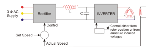
Fig: closed loop self controlled synchronous motor
- It is used when highly accurate speed control is required.
- In this method, the inverter output frequency is determined by the speed of the rotor. The speed of the rotor is fed back to the differentiator.
- The difference between the preset speed and the actual speed is fed to the rectifier. Accordingly, the inverter changes the frequency and adjusts the speed of the motor.
- We get more accurate control over the motor speed with the closed loop operation.
- For example, if speed gets reduced (due to increase in load), the stator supply frequency gets reduced so that the rotor stays in synchronism with the stator magnetic field.
- No spontaneous oscillation or hunting occurs in this method.
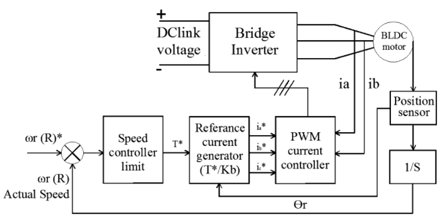
Fig: Block Diag of BLDC
A Brushless DC Motor is similar to a Brushed DC Motor but as the name suggests, a BLDC doesn’t use brushes for commutation but rather they are electronically commutated. In conventional Brushed DC Motors, the brushes are used to transmit the power to the rotor as they turn in a fixed magnetic field.
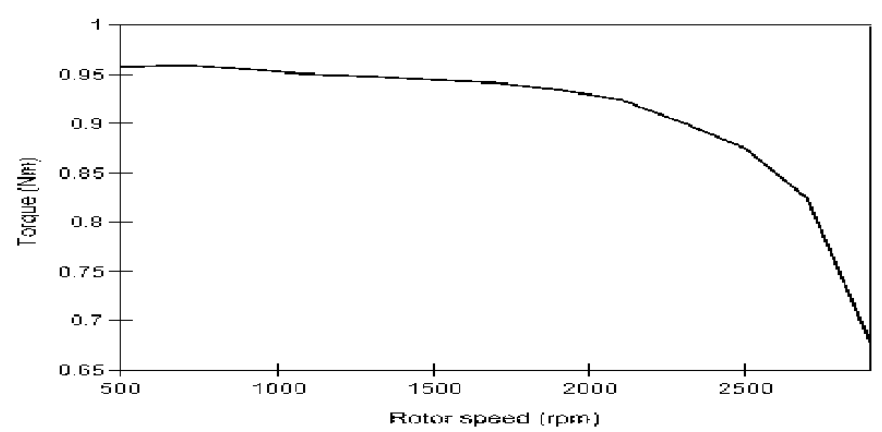
Fig: speed – torque characteristics
.
Reference Books
[R1] B. K. Bose, “Modern Power Electronics and AC Drives”, Pearson Education
[R2] Malcolm Barnes, “Practical Variable Speed Drives and Power Electronics”, Elsevier
Newnes Publications
[R3] V. Subrahmanyam, “Electric Drives: Concepts and Application”, Tata Mc-Graw Hill
(An imprint of Elsevier)
[R4] M.D. Singh and Khanchandani “Power Electronics”, Tata Mc-Graw Hill
[R5] Austin Huges, “Electrical motor and drives: Fundamental, types and applications”,
Heinemann Newnes, London
[R6] Tyagi MATLAB for engineers oxford (Indian Edition)