Unit – 1
Fundamentals of Protective Relaying
1). An electrical power system consist of generators transformers transmission & Distributed lines etc.
2). Short circuits & other abnormal conditions often occure on a power system.
3). The heavy current associates short circuit is likely to cause damage to equipment if suitable protective relays & circuit breakers are not provided for the protection of each section of the power system.
4). If a fault occurs in an element of a power system an automatic protective protective device is needed to isolate the faulty element as quickely as possible to keep the healthy section of the system in normal operation.
5). The fault must be cleared within a fraction of second.
6). If a short circuit persistson a system for a longer period, it may cause damage to some important sections of the system.
7). A heavy short ckt current may cause a fire. It may spread in the system and damage a part of it.
8). The system vtg may reduce to a low level and individual generators in a power station or groups of generators in different power stations may lose synchronism.
9). Thus, an uncleared heavy short circuit may cause the total failure of the system.
10). A protective scheme includes C.B. & protective relays to isolate the faulty section of the system from the healthy sections.
11). A C.B. Can disconnect the faulty element of the system when it is called upon to do so by the protective relay.
12). The function of a protective relay is to detect & locate a fault and issue a command to the C.B. To disconnect the faulty element.
13). It is a device which senses abnormal conditions on a power system by constantly monitoring electrical quantities of the system, which differ under normal and abnormal condition.
14). The basic electrical quantities which are likely to change during abnormal conditions are current, voltage, phase-angle (direction) & frequency.
15). Protective relays utilise one or more of these quantities to detect abnormal conditions on a power system.
16). Protection is needed not only against b.c. But also against any other abnormal conditions which may arise on a power system.
17). A few examples of other abnormal conditions are overspeed of generators & motors, over-vtg under frequency loss of excitation, overheating of stator and rotor of an alternator, etc protective relays are also provided to detect such abnormal conditions and issue alarm signals to alert operators or trip C.B.
1). Faults are caused either by insulation failure or by conducting path failures.
2). The failure of insulation results in s.c. Which are very harmful as they may damage some equipment of the power system.
3). Most of the faults on transmission and distributed lines are caused by overvoltages due to lightning or switching surges or by external conducting object falling on overhead lines.
4). Over voltages due to lightning or switching surges cause flashover on the surface of insulators resulting in short circuit.
5). Sometimes, insulators get punctured or break. Sometimes, certain foreign particles such as fine cement dust or soot in industrial areas or salt in coastal areas or any dirt in general accumulates on the surface of string and pin insulators.
6). This reduces their insulation strength and cause flashovers.
7). Short circuits are also caused by tree branches or other conducting objects falling on the overhead lines.
8). Birds also cause faults on overhead lines if their bodies touch one of the phases and the earth wire.
9). If the conductors are broken, there is a failure of the conducting path and the conductors becomes O.C.
10). If the broken conductor falls to the ground, it results in a S.C. Joint failures on cables or overhead lines are also a cause of failure of the conducting path.
11). The opening of one or two of the three phases makes the system unbalances unbalanced currents flowing in rotating machines set up harmonics, thereby heating the machine in short period of times.
12). Therefore, unbalancing of the lines is not allowed in the normal operation of power system.
13). Other causes of faults on overhead lines are : Direct lightning strokes, aircraft, snakes, ice & snow loading, abnormal loading, storms, earthquakes, creepers, etc.
14). In the case of cables, transformers, generators & other equipment, the cause of faults are : failure of the solid insulation due to aging heat, moisture or overvoltages, mechanical damage, accidental contact with earth or earthed screen, flashover due to over voltages, etc.
15). Sometimes, C.B. May drip due to errors in the switching operations, testing or maintenance work, wrong connections defects in protective device, etc.
16). Certain faults occur due to the poor quality of system components or because of faulty system design.
Two broad classification of faults are :
1). Symmetrical Faults
2). Unsymmetrical Faults
1). Symmetrical Faults :-
A three-phase fault is called a symmetrical type of fault. In a 3-Q fault, an the three phases are short circuited. There may be two situations all the three phases may be short circuited to the ground or they may be short-circuited withoud involving the ground.
2). Unsymmetrical Faults :-
Single phase to ground, two phase to ground, phase to phase short circuits, single phase O.C and two phase O.C. Are unsymmetrical types of faults.
i). Single phase to ground fault( L - G ) fault :-
A short circuit between any one of the phase conductors and earth is called a single phase to ground fault. It may be due to the failure of the insulation between a phase conductor & earth or due to a phase conductor breaking and falling to the ground.
Ii). Two phase to ground (2L - G)fault :-
A short circuit between any two phases and the earth is called a double line to ground or a two phase to ground fault.
Iii). Phase to phase (L - L) fault :-
A short circuit between any two phases is called a line to line or phase to phase fault.
Open Circuited Phases :-
This type of fault is caused by a break in the conducting path. Such fault occure when one or more phase conductors break or a cable joint or a joint on the overhead lines fails. Such situations may also arise when C.B. Or isolators open but fail to close one or more phases.
Simultaneous Faults :-
Two or more faults occurring simultaneously on a system are known as multiple or simultaneous fault. In simultaneous faults, the same or different types of faults may occure at the same or different points of the system. An example of two different types of faults occurring at the same point is a single line to ground fault on one phase and breaking of the conductor of another phase both simultaneously present at the same time.
The most dangerous type of fault is a short circuit as it may have the following effects on a power system, if it remains uncleared.
i). Heavy short circuit current may cause damage to equipment or any other element of the system due to overheating and high mechanical forces set up due to heavy current.
Ii). Arc associated with short circuits may cause fire hazards such fires resulting from arcing, may destroy the faulty element of the system there is also a possibility of the fire spreading to other parts of the system if the fault is not isolated quickly.
Iii). There may be reduction in the supply vtg of the healthy feeders, resulting in the loss of industrial loads.
Iv). S.C. May cause the unbalancing of supply vtg and currents, thereby heating rotating m/c.
v). There may be a loss of system stability, individual generators in a power station may lose synchronism, resulting in a complete shutdown of the system.
Vi). The above faults may cause an interruption of supply to consumers, thereby causing a loss of revenue.
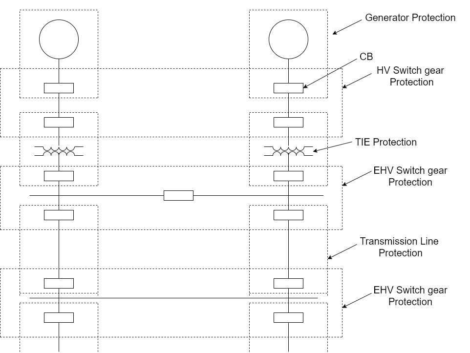
1]. A power system consists generators, J/F, bus-bars, transmission & distributed lines etc.
2]. There is a separate protective scheme for each piece of equipment or element of the power system, such as generator protection, T/F protection, Transmission line protection, bus-bar protection etc.
3]. Thus, a power system is divided into a number of zones for protection.
4]. A protective zone cover or at the most two elements of power system.
5]. The protective zones are planned in such a way that the entire power system is collectively covered by them and thus no part of the system unprotected.
6]. Adjacent protective zones must overlap each other, failing which a fault on the boundary of the zones may not lie in any of the zones and hence no C.B would trip.
7]. Thus, the overlapping between the adjacent zone is unavailable.
8]. If a fault occurs in the overlapping zone in a properly protected scheme, more C.B. Of the system would trip.
9]. A relatively low extent of overlap reduces the possibility of tripping of too many C.B.
1]. It has been already explained that a power system is divided into various zones for its protection.
2]. There is a suitable protective scheme for each zone.
3]. If a fault occurs in a particular zone, it is the duty of the primary relays of that zone to isolate the faulty element.
4]. The primary relay is first line of defence.
5]. If due to any reason, the primary relay fails to operate, there is a back-up protective scheme to clear the fault as a second line of defence.
6]. The causes of failure of protective scheme may be due to the failure of various elements.
7]. The reliability of a protective scheme should be at least 95% with proper design, installation and maintenance of the relays, C.B., trip mechanism, wiring etc a very high degree of reliability can be achieved.
8]. The back-up relays are made independent of those factors which might cause primary relays to fail.
9]. A back-up relay operates after a time delay to give the primary relay sufficient time to operate.
10]. When a back-up relay operates, a larger part of the power system is disconnected from the power source, but this is unavoidable.
There are three types of back-up relays,
1]. Remote Back-up :-
When back-up relays are located at a neighbouring station, they back-up the entire primary protective schemes which includes relay, C.B., C.T., P.T. & other elements in case of a failure of the primary protection scheme. It is the cheapest & the simplest form of back-up protection and is widely used back-up protection for transmission line. It is most desirable because of the fact that it will not fail due to the factors causing the failure of the primary protection.
2]. Relay Back-up :-
This is kind of a local back up in which an additional relay is provided for back-up protection. It trips the same C.B. If the primary relay fails and this operation takes place without delay. Though such a back-up is costaly, it can be recommended where a remote back-up is not possible. For back-up relay, principles of operation that are different from those of the primary protection are desirable. They should be supplied from separate curren& potential T/F.
3]. Breaker Back-up :-
This is also a kind of a local back-up. This type of a back-up is necessary for a bus-bar system where a number of C.B are connected to it. When a protective relay operates in response to a fault but the C.B. Fails to trip, the fault is treated as a bus bar fault. In such a situation, it becomes necessary that all other C.B. On that bus bar should trip. After a time-delay, the main relay closes the contact of a back-up relay which trips on other C.B. On the bus, if the proper breaker does not trip within a specified time after its trip coil is energised.
1]. Selectivity or Discrimination :-
Selectivity is the quality of a protective relay by which it is able to discriminate betn a fault in the protected section and the normal condition. Also it should be able to distinguish whether a fault lies within its zone of protection or outside the zone. Sometimes, this quality of the relay is also called discrimination. When a fault occurs on a power system only the faulty part of the system should be isolated. No healthy part of the system should be deprived of electric supply and hence should be left intact. When generators of two interconnected power plants lose synchronism because of disturbances, hearly current flows through the equipment and lines. The protective relay should be able to distinguish between a fault & healthy part. Thus, a protective relay must be able to discriminate between those condition for which instantaneous tripping is required and those for which no operation is required.
2]. Reliability :-
A protective system must operate reliably when a fault occurs in its zone of protection. The failure of a protective system may be due to the failure of any one or more elements of the protective system. It’s important elements are the protective relay, C.B., P.T., C.T., wiring, battery, etc. To achieve a high degree of reliability, greater attention should be given to the design, installation, maintenance and testing of various elements of the protective system. Robustness and simplicity of the relaying equipment also contribute to reliability.
3]. Sensitivity :-
The protective relay should operate when the magnitude of the current exceeds the preset value. This value is called the pick-up current. The relay should not operate when the current is below its pick-up value. A relay should be sufficiently sensitive to operate when the operating current just exceeds it’s pick-up value.
4]. Stability :-
Stability is defined as the quality of protective system by virtue of which, the protective system remains inoperative and stable under certain specified condition such as system disturbances through faults transient, etc.
Consider protection of T/F, for faults beyond the protected zone the protection of T/F should remain stable. To achieve such stability, the relay CT’s, protective scheme design and type of disturbances are important.
5]. Fast Operation :-
A protective system should be fast enough to isolate the faulty element of the system as quickly as possible to minimise damage to the equipment and to maintain the system stability.
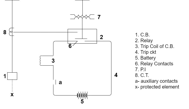
1]. The protected ckt is shown by dashed line.
2]. When a fault occurs in the protected ckt, the relay connected to the CT and PT actuates and closes it’s contacts.
3]. Current flows from the battery in the trip circuit.
4]. As the trip coil of the C.B. Is energized the C.B. Operating mechanism is actuates and it operates for the opening operation.
5]. Auxiliary switch is an important device in the trip circuit of the C.B.
6]. It is mechanically interlocked with the operating mechanism of the C.B. Such that, when the C.B. Opens, the auxiliary switch also opens thereby disconnecting trip circuit.
7]. The current in the trip ckt is interrupted by auxiliary switch and not by the protective relay contacts.
8]. The relay contacts are light and delicate so that the weight of moving parts is low and consumption of relay is low.
9]. Hence, relay contacts are not designed to interrupt the current in trip circuit.
1]. Based on technology :-
i). Electromagnetic Relays
Ii). Static Relays
Iii). Microprocessor Based Relays
2]. Based on their function :-
i). Over current Relays
Ii). Under voltage Relays
Iii). Impedance Relays
Iv). Underfrequency Relays
v). Directional Relays etc
3]. Protective Schemes :- It includes one or more relays of the same or different types.
i). Over current Protection
Ii). Distance Protection
Iii). Carrier-current Protection
Iv). Differential Protection
Induction Disc Relay :-
1). There are two types of construction of induction disc relays namely the shaded pole type and Watt hour meter type.
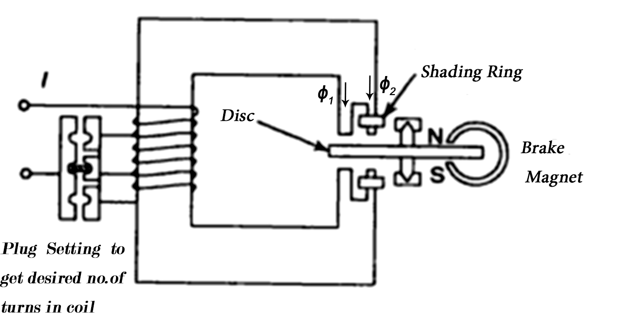
2). The rotating disc is made up of aluminium.
3). In a shaded pole type construction, a c-shaped electromagnet is used.
4). One half of each pole of the electromagnet is surrounded by a copper band known as shading ring.
5). The shaded portion of the pole produces a flux which displaces in space
And time with respect to the flux produced by the unshaded portion of the
Pole.
6). Thus two alternating fluxes displaced in space & time cuts the disc and
Produce eddy currents in it.
7). Torques are produced by the interaction of each flux with the eddy current produces by the other flux.
8). The resultant torque causes the disc to rotate.
9). A permanent magnet is employed to produce eddy current braking to the disc.
10). When the operating current exceeds pick-up value driving torque is produced and the disc accelerates to a speed where the braking torque balences the driving torque.
11). The disc rotates at a speed proportional to driving torque.
12). It rotates at a constant speed for a given current.
13). The disc inertia should be as small as possible, so that it should stop rotating as soon as the fault current disappear.
14). After the cessation of the fault currents the disc will travel to some distance due to inertia.
15). This distance should be minimum. It is called over-run of disc.
16). A brake magnet is used to minimise over-run.
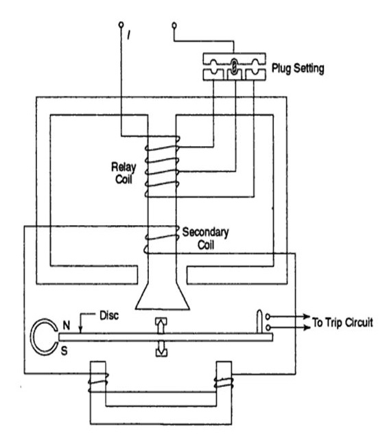
Watt Hour Meter type induction disc relay
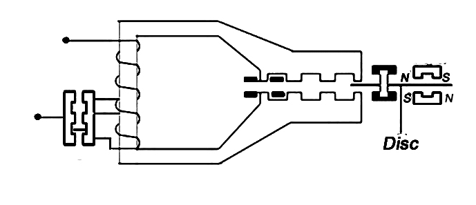
1]. It consist of an E-shape Electromagnet and a v-shaped electromagnet with a disc free to rotate in between.
2]. The E-shaped magnet produces flux φ1 and the v-shaped magnet produces flux φ2.
3]. The phase angle ϴ between the fluxes is adjusted by a reactance in parallel with the secondary winding.
4]. Torque is produced by interaction between flux & the eddy currents in the disc ( produced by flux φ1&φ2 ).
5]. The relay coil is tapped at several points. The current setting is selected by inserting a knob to take desired no of turns of the coil in the ckt.
6]. The operation of induction relay can be controlled by opening secondary coil, as opening of this coil makes relay inoperative.
Induction Cup Relay :-
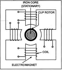
1]. This relay has two, four or more electromagnets in stator. These are energized by the relay coils.
2]. The rotor consists of a hollow metallic cylindrical cup. Control spring & moving contact carried on arm attached to spindle of cup.
3]. The rotor is free to rotate in the gap between the stationary iron and the electromagnets.
4]. In this type of relay, the eddy currents are produced in the metallic cup.
5]. These currents interact with the flux produced by the other electromagnet and torque is produced.
6]. The theory is similar to that of disc type induction relay.
1]. Flux φ1&φ2 are produced in a disc type construction by shading technique.
2]. In Wattmetric type construction, φ1 is produced by the upper magnet &φ2by the lower magnet.
3]. In case of the cup type construction, φ1&φ2 are produced by pairs of coils.
4]. The torque theory is true for both disc type & cup type induction relay.
5]. The following figure shows how force is produced in a rotor which is cut by φ1&φ2.
6]. These fluxes are alternating quantities and can be expressed as,
φ1 = φ1mSinwt
φ2 = φ2mSin(wt + ϴ)
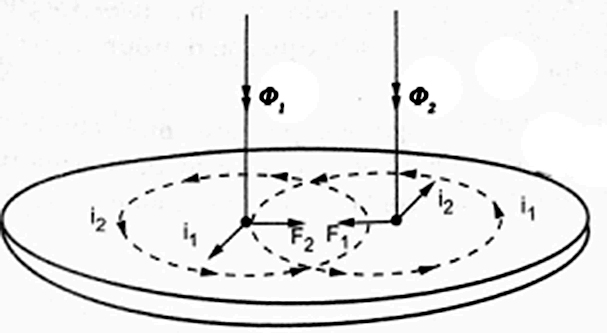
Whereϴ is the phase difference betn φ1&φ2. The flux φ2 leads φ1 by ϴvtg induced in the rotor are,
e1α dφ1/dt
αφ1mCos wt
e2α dφ2/dt
αφ2mCos( wt + ϴ )
As the path of eddy currents in the rotor has negligible self-inductance it may be assumed that the induced eddy currents in the rotor are in phase with their vtg.
i1αφ1mCos wt
i2αφ2mCos( wt + ϴ )
The current produced by the flux interacts with the other flux and vice versa. The forces produced are,
F1αφ1i2
αφ1mSinwt φ2mCos( wt + ϴ )
αφ1m φ2m Cos( wt + ϴ ) Sinwt
F2αφ2i1
αφ2mSin(wt + ϴ ) φ1mCoswt
αφ1m φ2m Sin( wt + ϴ ) Coswt
As these forces are in opposition, the resultant force is,
F = F2 – F1
αφ1m φ2m [Sin(wt + ϴ) Coswt - Cos(wt + ϴ) Sinwt]
αφ1m φ2m Sin ϴ
F αφ1φ2 Sin ϴ
Overcurrent Protection :-
A protective relay which operates when the load current exceeds a preset value, is called an overcurrent relay.
The value of the preset current above which the relay operates is known as its pick-up value.
An overcurrent used for the protection of distributed lines, large motors, power equipment etc.
A scheme which incorporates overcurrent relays for the protection of an element of a power system, is known as an overcurrent scheme or overcurrent protection. An overcurrent scheme may include one or more overcurrent relays.
Time – current Characteristics :-
A wide variety of time current char is available for overcurrent relays.
1]. Definite – time overcurrent Relay :-
A definite – time overcurrent relay operates after a predetermined time when the current exceeds it’s pick-up value. Curve (a) shows the time current characteristics for this type of relay. The operating time is constant, irrespective of the magnitude of the current above the pick-up value. The desired definite operating time can be set with the help of an intentional time-delay mechanism provided in the relaying unit.
2]. Instantaneous overcurrent Relay :-
An instantaneous relay operates in a definite time when the current exceeds it’s pick-up value. The operating time is constant. There is no intentional time delay. It operates in 0.1s or less sometimes the term like “high set” or “high speed” is used for very fast relays having operating times less than 0.1s.
3]. Inverse-time overcurrent Relay :-
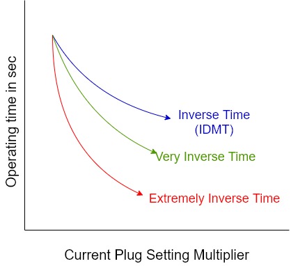
An Inverse-time overcurrent relay operates when the current exceeds it’s pick-up value. The operating time depends on the magnitude of the operating current. The operating time decreases as the current increases. Curve (b) shows the inverse time-current characteristics of this type of relay.
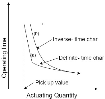
4]. Inverse Definite Minimum time o/c Relay (IDMI) :-
This type of a relay gives an inverse-time current characteristics at lower values of fault current & definite – time char at higher values of the fault current. Generally an inverse – time char is obtained if the value of the plug setting multiplier is below 10. For the values of plug setting multiplier between 10 & 20, the characteristic tends to become a straight line i.e towards the definite time char.
5]. Very Inverse – time overcurrent relay :-
A very inverse – time overcurrent relay gives more inverse characteristic than that of a plain inverse relay or the I.D.M.T. Relay. It’s time – current characteristic lies between an I.D.M.T. Char and extremely inverse char as shown in fig. The very inverse char gives better selectivity than I.D.M.T. Relay. Hence, it can be used where an I.D.M.T. Relay fails to achieve good selectivity. It’s recommended standard time – current char is given by,
t = 13.5 / I – 1
6]. Extremely inverse – time overcurrent relay :-
An extremely inverse time overcurrent relay gives a time – current char more inverse than that of the very inverse & I.D.M.T. Relay as shown in fig. When I.D.M.T. And very inverse relays are not suitable to be graded with fuses. The time – current char of an extremely inverse relay is
I2t = k
Overcurrent Protective Scheme :-
1]. Overcurrent protective schemes are widely used for the protection of distributed lines.
2]. A radial feeder may be sectionalised and two or more overcurrent relays may be used one relay for the protection of each section of the feeder as shown in fig.
3]. If fault occurs beyond c the C.B. At sub-station c should trip. The C.B. At A & B should not trip as far as the normal operation is concerned.
4]. If the relay at c fails to operate the C.B. At B should trip as a back-up protection
5]. Similarly, if a fault occurs between B and C, the C.b. At B should trip the C.B. At A should not trip.
6]. But in the case of failure of a relay or C.B. At B, the C.B. At A should trip.
7]. Thus it is seen that the relays must be selective with each other.
8]. For proper selectivity of the relays, one odf the following schemes can be employed depending on the system conditions.
I]. Time – graded system
II]. Current – graded system
III]. A combination of time and current grading
I]. Time – graded system :-
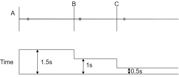
1]. In this scheme, definite – time overcurrent relays are used.
2]. When a definite – time relay operates for a fault current, it starts a timing unit which trips the C.B. After a preset time, which is independent of the fault current.
3]. The operating time of the relay is adjusted in increasing order from the far end of the feeder as shown in fig.
4]. The difference in the time setting of two adjacent relays is usually kept at 0.5s.
5]. When a fault occurs beyond C, All relays come into action as the fault current flows through all of them.
6]. The least time setting is for the relay placed at c so it operates after 0.5s and the fault is cleared.
7]. If the relay or C.B. At c fails the fault remains uncleared.
8]. In this situation after 1s, the relay at B will operate and the C.B. At B will trip.
9]. If the C.B. At B also fails to operate after 1.5s C.B. At A will trip.
II]. Current – graded system :-
1].In a current graded scheme, the reays are set to pick up at progressively higher values of current towards the source.
2]. The relays employed in this scheme are high set (high speed) instantaneous o/c relays.
3]. The operating time is kept the same for all relays used to protect different sections of the feeder.
4]. Ideally, the relay at B should trip for faults any where between B & C. But it should not operate for faults beyond c.
5]. Similarly, the relay at A shows trip for faults between A & B.
6]. The relay at c should trip for faults beyond c. This idea operation is not achieved due to the following reasons.

i]. The relay at A is not able to differentiate between faults very close to B which may be on either side of B. If a fault in the section BC is very close to the station B, the relay at A understands that is in section AB. This happens due to the fact that there is very little difference in fault currents if a fault occurs at the end of the section AB or in the beginning of the section BC.
Ii]. The magnitude of the fault current cannot be accurately determines as all the circuit parameters may not be known.
Iii].During a fault, there is a transient condition and the performance of the relays is not accurate.
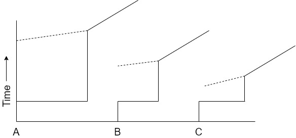
7]. Consequently to obtain proper discrimination, relays are set to protect only a part of the feeder usually about 80% since this scheme cannot protect the entire feeder, this system is not used alone. It may be used in conjunction with I.D.M.T. Relays as shown below.
III]. Combination of current & time – grading :-
1]. This scheme is widely used for the protection of distributed lines. I.D.M.T. Relays are employed in this scheme.
2]. They have the combined features of current and time – grading. I.D.M.T. Relays have current as well as time setting arrangements.
3]. The current setting of the relay is made according to the fault current level of the particular section to be protected.
4]. The relays are set to pick-up progressively at higher current levels, towards the source.
5]. The difference in operating times of two adjacent relays is kept 0.5s.
2 Current Setting :-
1]. The current above which an overcurrent relay should operate can be set.
2]. Supposethat a relay is set at 5A it will then operate if the current exceeds 5A. Below 5A, the relay will not operate.
3]. There are a number of tappings on the current coil available for current setting as shown in induction disc type relay.
4]. An overcurrent relay which is used for phase to phase fault protection can be set at 50% to 200% of the rated current in steps of 25%.
5]. The usual current rating of this relay is 5A. So it can be set at 2.5A, 3.75A, 5A,….10A.
6]. When the relay is set at 2.5A it will operate when the current exceeds 2.5A, when the relay is set at 10A, it will operate when current exceeds 10A.
7]. The relay which is used for protection against ground faults (earth fault relay) has setting 20% to 80% of the rated current in steps of 10%.
8]. The current ratings of an earth – fault relay is usually 1 Amp.
3 Plug setting Multiplier :-
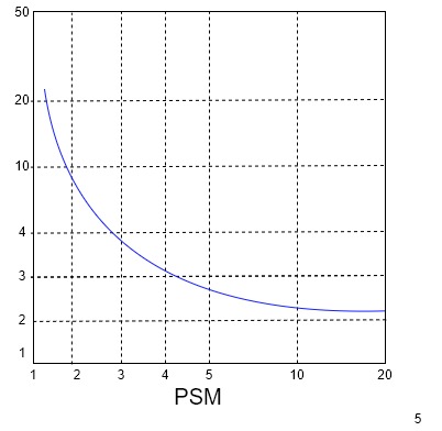
1]. If time – current curves are drawn, taking current in amperes on X-axis there will be one graph for each setting of the relay.
2]. To avoid this complex situation, plug setting multiplier taken on X-axis.
3]. The actual r.m.s. Current flowing in the relay expressed as a multiple of the setting current (pick-up current) is known as plug setting multiplier (PSM).
4]. Suppose the rating of a relay is 5A and it is set at 200% i.e. at 10A. If the PSM is 10 then 100A current is flowing.
If PSM = 4 then 40A current is flowing
PSM = 6 then 60A current is flowing.
Hence, PSM can be expressed as,
PSM = Primary current during fault (fault current)/ Relay current setting x C.T. Ratio
4 Time Setting :-
1]. The operating time of the relay can be set at a desired value.
2]. In induction disc type relay, the angular distance by which the moving part of the relay travels for closing the contacts can be adjusted to get different operating time.
3]. There are 10 steps in which time can be set.
4]. One term Time multiplier setting (TMS) is used for these steps of time setting.
5]. The values of TMS are 0.1, 0.2, . . . . . . 0.9, 1.
6]. Suppose that at a particular value of the current or plug setting multiplier (PSM), the operating time is 4s with TMS = 1. The operating time for the same current with TMS = 0.5 will be 4 x 0.5 = 2s. Theoperating time with TMS = 0.2 will be 4 x 0.2 = 0.8s.
5 Directional Overcurrent relay :-
1]. A directional overcurrent relay operates when the current exceeds a specified value in a specified direction.
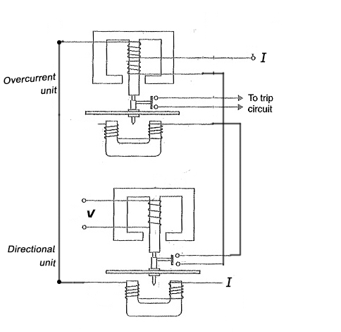
2]. Fig shows a directional overcurrent relay. It contains two relaying units, one overcurrent unit and the other a directional unit.
3]. For directional control, the secondary wdg of the overcurrent unit is kept open.
4]. When the directional unit operates, it closes the open contacts of the secondary wdg of the overcurrent unit.
5]. Thus a directional feature is attributed to the overcurrent relay.
6 Distance Protection :-
1]. Distance protection is the name given to the protection whose action depends upon the distance of the feeding point to the fault.
2]. The time of operation of such a protection is a function of the ratio of vtg& current i.e. Impedance.
3]. This impedance betn relay & fault depends upon the electrical distance between them.
4]. Types of distance relays are
a] Impedance relay b] Reactance Relay
c] Admittance or mho relays
5]. Distance Relays differ in principle from other forms of protection in that their performance is not governed by the magnitude of current or the vtg in the protected ckt but rather on the ratio of these two quantities.
6]. Distance Relays are actually double actuating quantity relays with one coil energized by vtg and other coil by current.
7]. The current element produces a positive or pick-up torque while the vtg element produces a negative or reset torque.
8]. The relay operates only when the V/I ratio faults below a predetermined value or set value.
9]. During a fault on a transmission line the fault current increases and the vtg at the fault point decreases.
10]. The VI ratio is measured at the location of CTs &PTs.
11]. Thevtg at PT location depends on the distance between PTs & fault. If the fault is nearer measured vtg is lesser and if the fault id farther, measured vtg is more.
a]. Impedance type Distance Relay :-
1]. An impedance relay is a vtg restrained over-current relay.
2]. The relay measures impedance upto the point of fault and gives tripping command if this impedance is less than the relay setting Z.
3]. The relay monitors continuously the line current through I through CT and the bus vtg V through PT and operates when the V/I ratio falls below the set value.

4]. The vtg element of the relay is excited through a PT from the line under protection and current element of the relay is excited from a CT in series with line.
5]. The portion AB of the line is the protected zone.
6]. Under normal operating condition the impedance of the protected line is Z.
7]. The relay is so designed it closes it’s contacts whenever impedance of the protected section falls below the set value i.e. Z.
8]. Now assumes that a fault occurs at point F1 in the protected zone.
9]. The impedance the ratio of the bus vtg and fault current (V/I), between the point where the relay is located and the point of fau;t will become less than Z and hence the relay operate.
10]. If the fault occur beyond the protected zone ( say at point F2 ) the impedance will be more than Z and the relay contacts do not close.
b]. Reactance Relay :-
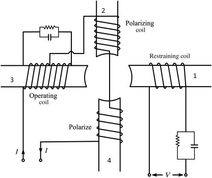
1]. It consists of two units – an over-current element developing positive torque and a current-vtg directional element which oppose the over-current element.
2]. This means, a reactance relay is an over current relay with directional restraint.
3]. The induction cup structure are best suited for actuating reactance type distance relays.
4]. It has a 4-pole structure carrying operating, polarizing and restraining coils.
5]. The operating torque is developed by the interaction of fluxes due to current carrying coils i.e. interaction of fluxes of poles 2,3 & 4 and the restraining torque is produces by the interaction of fluxes due to the poles 1,2 & 4.
6]. The operating torque will be proportional to I2 while restraining torque will be proportional to VI Cos(ϴ - 900).
7]. The desired max torque angle is obtained with the help of res-cap circuits, as illustrated in fig.
c]. MHo type distance relay :-
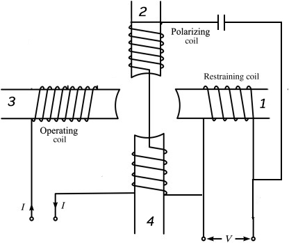
1]. MHo relay is a high speed relay and is also known as admittance relay.
2]. In this relay operating torque is obtained by the volt-ampere element and the restraining torque is developed dur to the vtg element.
3]. It means a MHo relay is a voltage restrained directional relay.
4]. The operating torque is developed by the interaction of fluxes due to poles 2,3 & 4 and the restraining torque due to poles 1,2 & 4.
* Differential Protection :-
1]. It operates on the principle of comparison between the phase angle and magnitudes of two or more similar electrical quantities.
2]. Comparing two electrical quantities in a ckt by means of differential relay is simple in application and positive in action e.g. In comparison of the current entering a line and the current leaving it, if more current enters the protected line than leaves it. The extra current must flow in the line.
3]. The difference between the two electrical quantities can operate a relay to isolate the ckt.
4]. A Differential relay is defined as the relay that operates when the phaser difference of two or more similar electrical quantities exceeds a pre-determined amount.
5]. It means that for a differential relay it should have a] two or more similar quantities and b] these quantities should have phase displacement (hormany approx. 1800) for the operation of the relay.
6]. Most of the differential relays are of the “current Differential” type in which phaser difference between the current entering the wdg and current leaving the wdg is used for sensing and relay operation.
7]. Differential protection principle is employed for the protection of generators, generator T/F units, T/F, Transmission line, large motors & Bus-Bar.
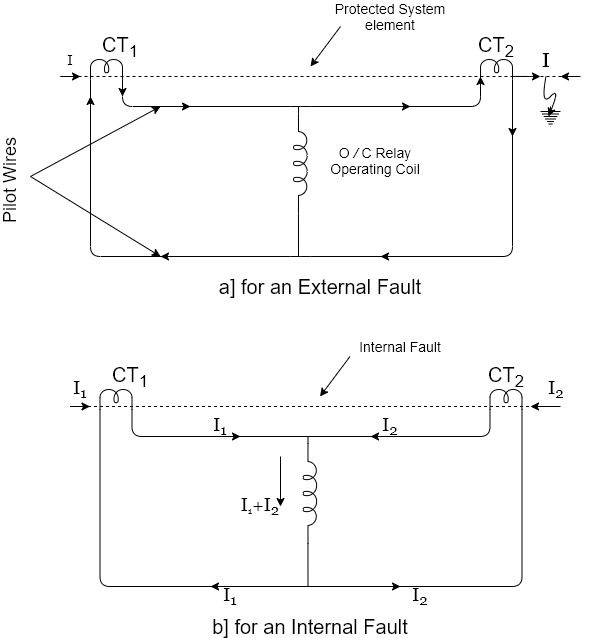
1]. The dotted line represents the system element that is to be protected by the differential relay.
2]. This system element might be a length of ckt, a portion of the bus or a wdg of a generator or that of T/F.
3]. A pair of CTs are fitted on either end of the section to be protected.
4]. These condaries of CTs are connected in series with the help of pilot wires in such way that they carry the induced currents in the same direction.
5]. The operating coil of an over-current relay is connected across the CT secondary ckt.
6]. Normally when there is no fault or there is an external fault [fig a], the current in the two CT’s secondary’s are equal and the relay operating coil therefore does not carry any current.
7]. But, when a short-circuit develop anywhere between the two CT’s, the conditions will exists as shown in fig.
8]. If the current flows to the fault from both side as shown, the sum of the CT secondary currents will flow through the differential relay.
9]. It is not necessary that fault current flows to the fault from both side to cause secondary current flow to the differential relay.
10]. In the other words, the differential relay current will be proportional to the phasor difference between the currents entering and leaving the protected element and if the differential current exceeds the relay’s pick-up value, the relay will operate.
1 Biased or Percentage Differential Relay :-
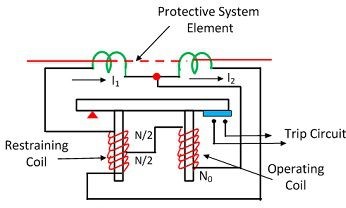
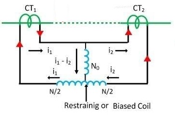
1]. This system consists of an additional restraining coil connected in the pilot wires, as shown in the fig and current induces in both CT’s flows though it.
2]. The operating coil is connected to the mid point of the restraining coil.
3]. The reason for using this modification in current differential relay is to overcome the trouble arising out of differences in CT ratios for high values of external short-ckt currents.
4]. The torque due to restraining coil prevents the closing of trip ckt contacts, while the torque due to operating coil tends to close the trip ckt contacts.
5]. Under normal operating conditions the torque developed by the restraining coil is greater than the operating coil torque.
6]. Thus the relay remains inoperative. When an internal fault occurs, the operating torque exceeds the restraining torque.
7]. Consequently the trip ckt contacts are closed to open the C.B.
8]. The restraining torque may be adjusted by varying the no of turns of the restraining coil.