Unit – 2
Fundamentals of arc interruption
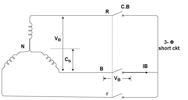
1]. Consider a circuit-Breaker connected to a generator on no-load at rated terminal vtg.
2]. The circuit-Breaker is in open position and the other side of C.B. Is short-circuited.
3]. Let the CB be closed at the instant when vtg of terminal B w.r.t. Neutral is zero.
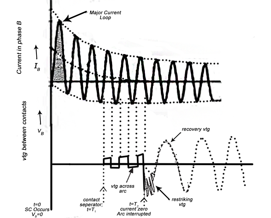
4]. In such a case the short ckt current in phase B will have maximum D.C. Component and the waveform of current Ib will be unsymmetrical about normal zero axis.
5]. The generator is on No load before t=0. Hence current is zero before t=0.
6]. At t=0 the short ckt is applied and the current increases to a high value during the first quarter cycle.
7]. The peak of the first major current loop is OM & this is max instantaneous value of current.
8]. During the short ckt the instantaneous peak value of the major current loop is called Making current (OM - KA).
9]. The C.B. Contacts separate after a few cycle since the relay and the operating mechanism takes at least a couple of cycle.
10]. Let us assume that the C.B. Contacts separate at t=T1 the r.m.s value of short ckt at the instant of contact separation is termed as Breaking Current.
11]. After the separation of contacts of the C.B. An arc is drawn between the contacts.
12]. The arc current varied sinusoid ally for a few cycles. At t=T2 a particular current zero, the dielectric strength of arc space builts up sufficiently so as to prevent the continuation of arc.
13]. At the current zero, this arc is extinguished & is interrupted.
Voltage between contacts :-
1]. At t=0 the contacts are closed & the vtg between them is zero.
2]. After the separation of the contact(t=T1) the vtg across contact increases.
3]. In fact this vtg is the voltage drop across the arc during arcing period.
4]. Duringsubsequent half cycles, the vtg across contacts increases due to increased arc resistance.
5]. Finally at t=T2 when arc gets extinguished a high frequency voltage transient appears across the contacts which is superimposed on power frequency system vtg.
6]. This high frequency transient vtg tries to restrike the arc. Hence it is called Restriking vtg or Transient Recovery vtg(TRV).
7]. The power frequency system voltage appearing between the poles after arc extinction is called Recovery vtg.
8]. If the dielectric strength of the medium between the contacts does not build up faster than the rate of rise of the transient recovery vtg. The breakdown takes place causing re-establishment of the arc.
9]. If the dielectric strength of the contact space builts up very rapidly so that it is more than the rate of rise of transient recovery vtg the CB interrupts the current successfully.
Modes of Arc Extinction :-
Two modes of Arc interruption can be identified.
1]. High resistance interruption
2]. Low resistance or zero-point interruption
1]. High Resistance Interruption :-
The high resistance interruption is obtained by increasing the resistance of arc.
Rarc = Varc / iarc
Assuming iarcto be constant the resistance of the arc can be increased by increasing vtg of the Varc.
In high resistance interruption method the length of the arc is increased so as to increase the vtg across arc.
The vtg of the arc is increased till it more than the system vtg across the contacts. At this point the arc gets extinguished.
The method is used in low & medium vtga.c and d.c C.B.
The arc resistance is increased by following methods.
a]. Lengthning of arc by means of arc runners :-
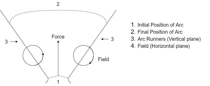
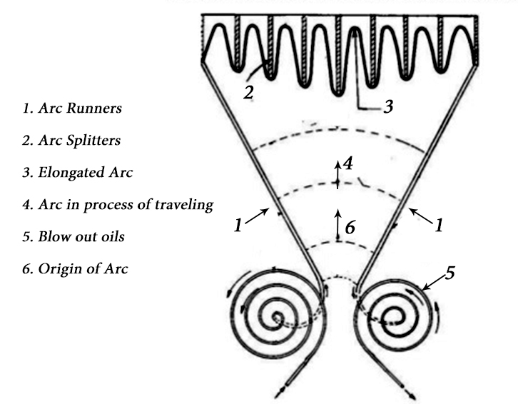
Arc runners are horn-like blades of conducting material which are connected to arcing contacts with their tips radiating upwards in ‘V’ shape.
The arc originates at bottom and blows upward by electromagnetic force. The tips of the arc more upwards along arc runners rapidly. The length of the arc increases & arc is extinguished.
b]. Splitting of Arc :-
The arc is elongated & split by arc splitters. These are specially made plates of resin bonded fibre glass. These are placed in the path perpendicular to the arc and the arc is pulled into them by electromagnetic force experienced by the arc by means of magnetic field applied in proper direction so as to pull the arc upwards. When the arc is pulled in space between the plates, it gets elongated constrained split & cooled. By virtue of these effects the arc gets extinguished.
c]. Cooling of Arc :-
Cooling of the arc brings about recombination of ionised particles. Cooling removes the head from the arc. Cooling is brought by bringing the arc is contact with cooler air.
2]. Low Resistance / Zero point Extinction :-
i]. This method is employed in a.c arc interruption. Actually the alternating current passes through zero 100 times / sec in 50 cycles current wave.
Ii]. At every current zero the arc vanishes for a brief moment.
Iii]. However, the arc appears again with the rising current wave.
Iv]. In AC C.B. The arc is interrupted at a current zero.
v].At current zero, the space between contacts is deionised quickly by introducing from unionised medium such as oil or fresh air or SF6 gas between contacts.
Vi]. The dielectric strength of the contact space increases to such an extent that the arc does not continue after current zero.
Vii]. A high vtg may appear across the contacts.
Viii]. The high vtg may re-establish the arc, if the dielectric strength of gap is less than the restrikingvtg.
Ix]. In that case the arc continues for another half cycle & may get extinguished at next current zero.
Arc Interruption Theories :-
I]. Slepian’sTheory :-
1]. Slepians described the arc extinction process as the race between dielectric strength and Restrikingvtg.
2]. If the dielectric strength builts up rapidly so that it is always greater than the restrikingvtg the arc does not restrike.
3]. If dielectric strength is less the arc restrikes.
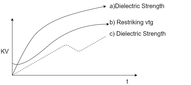
4]. According to the theory, if the dielectric strength of contact gap is more than the restrikingvtg as shown curve a] above b] the arc gets extinguished.
5]. But if the dielectric strength builts as in curve c] the arc restrikes.
Drawbacks :-
1]. The theory assumes that the restrikingvtg and build up of dielectric strength are comparable quantities. This assumption is not quite correct. These two entities are not identical.
2]. This theory does not consider the energy relations in the arc extinction.
3]. This theory does not cover the arching phase. Hence it is Incomplete.
Energy Balance Theory :- [ Cassie ]
Cassie made the following assumptions in his Energy Balance Theory.
1]. Arc consist of a cylindrical column at a sub-satanically uniform temperature over it’s cross-section with well defined boundary.
2]. There is a uniform distribution of energy in this column i.e. Volume energy density is constant for the complete column of the arc.
3]. The temp remains constant.
4]. The cross-section of arc adjust itself to accommodate the arc current.
5]. Power dissipation is proportional to arc cross-sectional area of arc column. Cassie expended the energy equation as,
DQ/dt = EI – N
Where,
Q = Energy content / cm of arc length
E = volts/cm
I = Total current
N = Total power loss/cm
6]. Breakdown occurs if power feed in the arc is more than power loss.
7]. The theory is approximately true for high currents.
The arc extinction process in C.B. Is influenced by several aspects such as :
1]. Speed of contact
2]. Material of contact
3]. The pattern of flow of quenchingmedium.
4]. Magnitude of arc current & variation of arc diameter.
5]. Energy liberated during arching, energy in system inductance.
6]. Rate of Rise of transient recovery vtg.
7]. Rate of gain of dielectric strength.
8]. Instant of contact separation with respect to vtg current.
Figure shows an equivalent electrical ckt where L & C are the Inductance and capacitance per phase of the system up to the point of C.B. Location respectively.

1]. When the C.B. Is closed, the short ckt current flows through R.L. & the contacts of the C.B. The capacitance C being short circuited by fault.
2]. When the C.B. Contacts are opened and the arc is extinguished, the current ‘i’ is diverted through the Capacitance C, resulting in a transient condition.
3]. The inductance and the capacitance form a series oscillatory circuit.
4]. The vtg across the capacitance which is restriping vtg rises & oscillates, ( as shown ), The natural frequency of the oscillation is given by,
fn = 1/2 π 1/ √LC
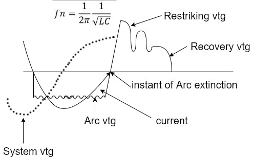
5]. The vtg across the capacitance which is the vtg across the contacts of the C.B. Can be calculated in terms of L, C, fn and system vtg.
The mathematical expression for transient condition is as follows,
L di/dt + 1/c ∫idt = E - (A)
WhereE is the system vtg at the instant of arc interruption. As the transient oscillation is a fast phenomenon E can be regarded as a constant for a short duration,
i = dq/dt = d(CVc)/dt [ Vc = vtg across capacitor]
Therefore, di/dt = d2(CVc) / dt2 = Cd2Vc/dt2 - (1)
∫idt/C = q/C = Vc - (2)
Substitute (1) & (2) in equation (A), we get
LCd2Vc / dt2 + Vc = E
Taking Laplace Transform both sides,
LCSL VC(S) + VC(S) = E/S
Where VC(S) is L.T of Vc
VC(S) [LCS2 + 1] = E/S
VC(S) = E / S[LCS2 + 1]
VC(S) = E / LCS(S2 + 1/LC)
Wn = 1/ √LC therefore Wn2 = 1/LC
VC(S) = Wn2E / S( S2 + Wn2 ) = WnE/S (Wn / S2 + Wn2)
Taking Inverse Laplace Transform, we get,
VC(t) = WnE ∫0tSinwnt
= WnE[ -cosWnt/Wn ]0t
As VC(t) = 0 at t = 0, constant = 0
VC(t) = E (1 - cosWnt) [ - (cosWnt – 1) cos0 = 1]
VC(t) = E [1 – cos1 / √LC t]
= Restriping vtg
The max value of Restriping vtg = 2 Epeak
= 2 x peak value of system vtg
The Rate of Rise of Restriping vtg (RRRV)
= dE / dt (1 – CosWnt)
= Wn E SinWnt
The maximum value of RRRV = WnE
= WnEpeak
Problems :- [ Restriking Voltage ]
1]. For a 132 Kv system, the reactance and capacitance upto the location of the C.B. Is 3Ω and 0.015 µF, respectively. Calculate the following,
a]. The frequency of transient oscillations.
b]. The max value of restrikingvtg across the contact of C.B.
c]. Themax value of RRRV.
a]. The frequency of transient oscillations :-
L = 3/2π50 - [XL = 2πFL]
= 3/100π = 0.00954 H
fn = 1/2π√LC
= 1/2 π √0.00954 x 0.015 x 10-6
= 105 / 2 π x 1.1962 = 105 / 7.5241
fn = 13.281 KHz
b]. Restrikingvtg :-
Vc = E [1 – CosWnt ]
Max value of Restrikingvtg = 2 Epeak
= 2 x 132/√3 √2 (√3 for φ√2 forpeak )
Max Value of Restrikingvtg = 215.56 Kv
c]. Max value of RRRV = WnEpeak
= 2 π fn x 132 /√3 x √2 x 1000
= 2 π x 13.291 x 1000 x 132 / √3 x √2 x 1000 V/S
= 9010.45 x 106 V/S
Max value of RRRV = 9.01045 KV/S
2]. In a 132 Kv system the inductance and capacitance upto the location of the C.B. Are 0.4 H and 0.015 µF respectively. Determine
a] Max value of the restrikingvtg across the contacts of the C.B.
b] Frequency of the transient oscillations
c] Maximum value of RRRV
Ans a] 216 Kv b] 2.06 KHz c] 1.39 Kv / µS.
a]. Maximum value of Restrikingvtg :-
Max value of restrikingvtg = 2 Epeak
= 2 x 132 / √3 x √2
= 216 Kv
b]. Frequency of transient oscillations :-
fn = 1 / 2 π √LC
= 1 / 2 π √0.4 x 0.015 x 10-6
fn = 2.06 KHz
c]. Max value of RRRV :-
Max value of RRRV = WnEpeak
= 2 π fn x 132 /√3 x √2 x 1000
Max value of RRRV = 1.39 Kv/ µS
3]. In a 132 Kv system the reactance per phase upto the location of the C.B. Is 5Ω and capacitance to earth is 0.03 µF. Calculate
a] Maximum value of Restrikingvtg
b] Maximum value of RRRV
c] The frequency of transient oscillations
Ans a] 216 Kv b] 4.94 Kv / µS c] 729 Hz
3 Resistance Switching :-
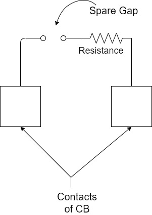
1]. To reduce the restrikingvtg, RRRV and severity of the transient oscillations, a resistance is connected across the contacts of the C.B.
2]. This is known as Resistance switching.
3]. The resistance is in parallel with the arc.
4]. A part of the arc current arc current flows through this resistance resulting in a decrease in the arc current and increase in the deionisation of the arc path and resistance of the arc.
5]. This process continues and the current through the shunt resistance increases and arc current decreases.
6]. Due to decrease in the arc current, Restrikingvtg and RRRV arc reduced.
7]. The resistance may be automatically switched in with the help of spare gap as shown in fig.
8]. The resistance switching is of great help in switching out capacitive current or low inductive current.
9]. The analysis of resistance switching can be made to find out the critical value of the shunt resistance to obtain complete damping of transient oscillations.
Fig shows the equivalent electrical ckt for such an analysis.
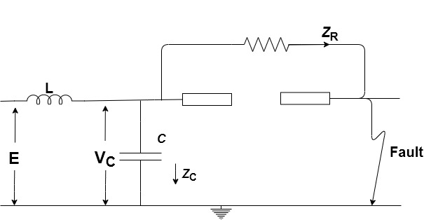
The vtg equation is given by,
L di/dt + 1/c ∫icdt = E and I = ic + iR
L d(ic + iR) / dt + Vc = E
L dic / dt + L diR / dt + Vc = E
ic = dq / dt = d ( CVc ) / dt
Therefore,
Dic / dt = d2 ( CVc ) / dt2 = C d2Vc / dt2
DiR / dt = d(Vc / R) / dt = 1/R dVc / dt
Substituting these values in main eqn
LC d2Vc / dt2 + L/R dVc / dt + Vc = E
Taking L.T, we get,
LCS2Vc( S ) + L/R S Vc( S ) + Vc( S ) = E/S
Other terms are zero, as Vc = 0 at t = 0
LCVc( S )[ S2 + 1 / RC S + 1 / LC ] = E / S
Vc( S ) = E / SLC [ S2 + 1 / RC S + 1 / LC ]
For no transient oscillations, all the roots of the equation should be real. One root is zero i.e. S = 0 which is real. For the other two roots to be real, the roots of the quadratic equation in the denominator should be real. For this the following condition should be satisfied.
[ ( 1 / 2RC )2 – 1 / LC ] >/ 0 or 1 / 4R2C2>. 1 / LC
4 / LC \< 1 / R2 C2
R2 \< LC / 4C2
R2 \< 1 / 4 1 / C
R \< 1 / 2 √L / C
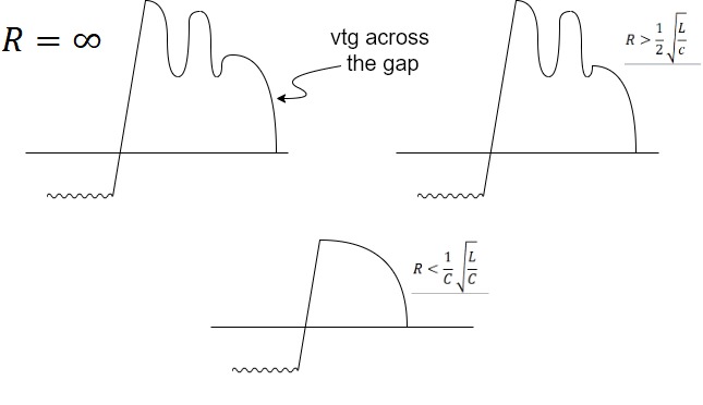
Therefore if the value of the resistance connected across the contacts of the C.B. Is equal to or less than 1 / 2 √L / C there will be no transient oscillation. If R > 1 / 2 √L / C, there will be oscillation.
R = 1 / 2 √L / C is known as critical resistance. The following figure shows the transient condition for three different values of R.
The frequency of damped oscillation is given by,
F = 1 / 2 π √1 / LC – 1 / 4C2 R2
4 Problems :- [ Resistance Switching ]
1]. In a 132 Kv system reactance & capacitance upto the location of the C.B. Is 5 Ωand 0.02 µF respectively. A res of 500 Ω is connected across the break of the C.B. Determine
a] Natural frequency of oscillation
b] Damped frequency of oscillation
c] Critical value of resistor
a]. Natural frequency of oscillation :-
= 1 / 2 π √LC = 1 / 2 π √0.0158 x 0.02 x 10-6 = 8.7 KHz
XL = 2 π fL
L = XL / 2 π f = 5 / 100 π = 0.0159H
b].Damped frequency of oscillations :-
f = 1 / 2 π √LC – 1 / 4C2 R2
= 1 / 2 π √ 1 / 0.0159 x 0.02 x 10-6 – 1 / 4 x ( 0.02 x 10⁻⁶ )2 x 5002
= 1 / 2 π √1010 / 3.18 – 1010 / 4
F = 3.9 KHz
c]. Critical value of resistor :-
R = 1 / 2 √ L / C = 1 / 2 √ 0.0159 / 0.02 x 10⁻⁶
R = 445 Ω
2]. In a 220 Kv system, the reactance and capacitance upto the location of C.B. Is 8 Ω& 0.025 µF respectively. A resistance of 600 Ω is connected across the contacts of the C.B. Determine
a] Natural frequency of oscillations
b] Damped frequency of oscillations
c] Critical value of resistance which will give no transient oscillations.
d] The value of resistance which will give damped frequency of oscillations, one forth of the natural frequency of oscillations.
L = 8 / 2 π 50 = 0.02544 H
a]. Natural frequency of oscillations :-
= 1 / 2 π √ 1 / LC
= 1 / 2 π √ 1 / 0.02544 x 0.025 x 10-6
= 6.304 KHz
b]. Damped frequency of oscillations :-
f = 1 / 2 π √ 1 / LC – 1 / 4C2R2
= 1 / 2 π √ 1 / 0.02544 x 0.025 x 10-6 – 1 / 4 ( 0.025 x 10⁻⁶ )2 x 6002
= 1 / 2 π √ 1010 / 6.36 – 1010 / 9
f = 3.413 KHz
c]. The value of critical resistance :-
R = 1 / 2 √ L / C
= 1 / 2 √ 0.02544 / 0.025 x 10⁻⁶
R = 504.35 Ω
d]. The damped frequency of oscillation is,
1 / 4 x 6.304 KHz = 1576 Hz
Now,
f = 1 / 2 π √ 1 / LC – 1 / 4C2R2
1576 = 1 / 2 π √ 1 / 0.02544 x 0.025 x 10-6 – 1 / 4 ( 0.025 x 10⁻⁶ )2 x R2
1576 = 1 / 2 π √ 1010 / 6.36 – 1016 / 25R2
R = 520.8 Ω
5 Current Chopping :-
1]. When low inductive current is being interrupted and the arc quenching force of the C.B. Is more than necessary to interrupt a low magnitude of current, the current will be interrupted before it’s natural zero instant.
2]. In such a situation the energy stored in the magnetic field appears in the form of high vtg which will cause restriking of the arc.
3]. The energy stored in the magnetic field is 1 / 2 L i2, if i is the instantaneous value of the current which is interrupted.
4]. This will appear in the form of electrostatic energy equal to 112 CV2.
5]. As these two energies are equal, they can be related as follows
1 / 2 L i2 = 1 / 2 CV2
V = i√ L / C
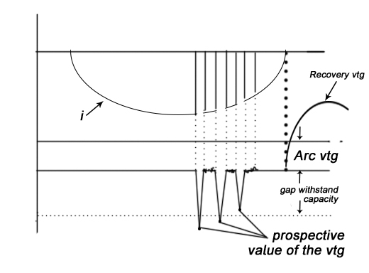
6]. If the value of V is more than the withstanding capacity of the gap between the contacts the arc appears again.
7]. Since the quenching force is more, the current is again chopped.
8]. This phenomenon continues till the value of V becomes less than the withstanding capacity of gap.
9]. The theoretical value of V is called the prospective value of vtg.
Interruption of capacitive current :-
1]. The interruption of capacitive current produces high vtg transients across the gap of the C.B.
2]. This occurs when an unloaded long transmission line or a capacitor bank is switched off.
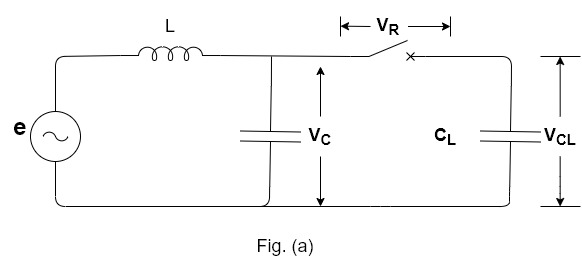
3]. Figure ( a ) shows an equivalent electrical ckt of a simple power system.
4]. C represents stray capacitance of the C.B. CL represents line capacitance.
5]. The value of CL is much more than C.
6]. Figure ( b ) shows transient vtg across the gap of the C.B when capacitive current is interrupted.
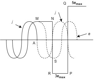
7]. At the instant M, the capacitive current is zero and the system vtg is max.
8]. If an interruption occurs, the capacitor CL remains charged at the max value of system vtg.
9]. After instant M, the vtg across the breaker gap is the difference of Vc& VCL. At instant N, the vtg across the gap is twice the maximum value of VC, at this moment the breaker may restrike.
10]. If the arc restrikes the vtg across the gap becomes practically zero.
11]. Thus, the vtg across the gap falls from 2 Vc max to zero.
12]. A severe high frequency oscillation occurs.
13]. The vtg oscillates about points between R & N i.e. between -3emax&emax. When restriking current reaches zero, the arc may be interrupted again.
14]. At this stage, the capacitor CL remains charged at the vtg, -3emax.
15]. At instant P, the system vtg reaches it’s +ve max shown by the point T in the figure and at this moment the vtg across the gap becomes 4emax.
16]. The capacitive current reaches zero again and there may be an interruption.
17]. If the interruption occurs at this moment the transient vtg oscillates between P( -3emax ) and Q( +5emax ).
18]. In this way, the vtg across the gap goes on increasing. But in practice, it is limited to 4 times the peak value of system vtg.
19]. Thus, it is seen that there is a problem of high transient vtg while interrupting a cap current.
Reference Books:
- [R1] Badri Ram, D. N. Vishwakarma, “Power System Protection and Switchgear”, Tata McGraw Hill Publishing Co. Ltd.
- [R2] J Lewis Blackburn , “Protective Relaying- Principles and Applications”, Dekker Publications.
- [R3] Prof. Dr S.A. Soman, IIT Mumbai, A Web course on “Digital Protection of power System”
- [R4] A.G. Phadke, J.S. Thorp ,Computer relaying for Power System , Research Studies Press LTD, England.(John Willy and Sons Inc New York)
- [R5] Mason C.R., “Art and Science of Protective Relaying”, Wiley Eastern Limited.
- [R6] Arun Ingole, “Switchgear and Protection”, Pearson.