Unit – 4
Static and digital relaying
Static Relay
- To a relay in which there is no armature or other moving element it and despotize is developed by electronic magnetic or other components without mechanical motion.
- The solid - state components used are transistors, diodes, register comparator or so on.
- The function of compression and measurement are accomplished by static ckt.
● Block diagram of static relay
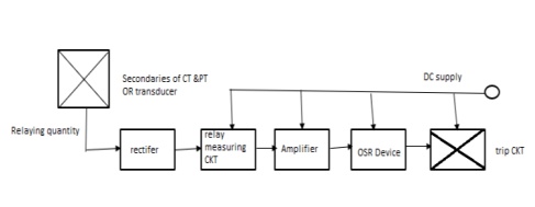
- Her the relaying quantity ie the o/p of CT or PT or transducer is rectified by a rectifiers.
- The rectified o/p is supplied to a measuring unit comparisons of comparators level, detectors, filters, logic ckt.
- The output is actuated when the dynamic i/p (ie. The relaying quantity) attained threshold value.
- This output of the measuring unit is amplified by amplifier and fed to the output unit device which is usually on electromagnetic one.
- The output unit energize the trip coil only when relag operates
- In a static relay the measurement is carried out by static circuit consisting of comparators level detector filter etc. While in a conventional electromagnetic relay it is done by comparing operating torque with restraining torque.
- The relaying quantity such as vtg/current is rectified and measured
- When the quantity under measurement attains certain well define value the output device is triggered and there the circuit breaker trip circuit is energized.
● Advantages of static relay
- The power consumption in case of static relay is usually much lower than that in electro mechanical equivalent
- Quick response, long life, shock proof, fewer problem of maintenance high reliability and high degree of accuracy.
- Absence of moving contact and associated problem of arcing bounce, erosion, replacement of contact etc.
- By combining various functional ckt. Several conventional relay can be substituted by single static relay e.g. a static relay can provide over current under voltage, single phasing, short ckt protection in an ac motor by in cooperating respective functional block.
- The characteristic of static relays are accurate and superior they can be aborted within curtain range as per protection needs.
● Disadvantages of static relay
- Semiconductor components are sensitive to electrostatic discharge, voltage spike or voltage transient.
- The characteristic of static relay are influenced by ambient temperature and again
- The static relay have low short time over load capacity compared with electromagnetic relays.
- Static relay are costlier for simple and single function then electromagnetic relay but for multifunction protection static relay prove economical
- Highly trained personnel are required for their servicing.
2.2 Numerical Relays :-Introduction and block diagram of numerical relay
● Numerical Relay
- In numerical relay there is an additional entity the software which runs in the background and which actually runs the relay.
- With the advent of numerical relays the emphasis has shifted from hardware to software.
- Hardware is more or less the same between any two numerical relays.
- What distinguishes one numerical relay from the other is software.
● Block diagram of numerical relay
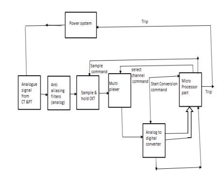
- The signal from CT and PT sampled directly and converted to digital from
- This is to make sure that the signal does not content frequency compound having a frequency gather than half of supply frequency.
- Is that signal are first pass their low pass filter which has to be an analog type filter because digital processing can only take place when the signal is properly shaped.
- The analog diagonal is sampled and hold constant during the time the value is converted to digital form
- The range of frequency that can be handled by analog to digital converter without sampling and hold circuit is extremely low.
- The sample and hold value is pass to ADCa multiplexer so as to accommodate large no of i/p signal
- The sample and hold circuit and ADC work under control of microprocessor and communicate with the help of control signal such as end of conversation signal
- The incoming digital value from ADC are stored in the Ram of and process by relay software.
- The microprocessor issue the trip signal on one of the bits at its output fort which is then suitable process so as to make it compatible with trip coil of C.B
- The microprocessor can also be used to communicate with other relay any other supervisor computer if so desired.
- The relaying program or release software which resides in the EPROM can only be guarded modified by personal.
- Then new beaters and functionality can be added to an exciting relay by upgraded its software
● Advantages of numerical relay
- The output of one current transformer can be used as input to many production function
- As mini functions are done by one numerical relay a lot aap space is saved by eliminating independent relay for each of the function
- The setting can be done from a remote computer
- The service and faceted value of the relay can be accessed from a remote computer
- Selection from a variety of characteristics each possible this will be useful if one feels the necessity to alter the original selected curvel characteristics based on operation experience.
- The software can be programmed modified act side to change the tripping logics such as inclusion of timer changing of tripping sequences etc.
● Disadvantage of numerical relay
Have I ever with all the above advantage and convenience they offered the numerical relay suffered from one major drawback ie not understanding and interpreting the language of other relay if the vender is different this problem is referred to access protocol matching this problem arised because now a day’s majority of the protection and Central equipment it is available with vendor specific hardware oriented solution which has give rise to a large number of manufacturer oriented communication protocol making it in convenient and costlier to make the two system of different manufacturers of communication with each other even device be longing to two different generation from the same manufacturer cannot communicate with each other.
- In order to represent the original message signal faithfully (without loss of information) it is necessary to take as many samples of the original signal as possible.
- Higher the number of simple closer it's the representation the number of sample depend on the sampling rate and the maximum frequency of the signal to be sampled
● Statement of sampling theorem
A continuous time signal x(t) can be completed represent in its sample from and recovered back from the sample from if the sampling frequency fs > 2w where w is the max frequency of the continuous time signal x(t)
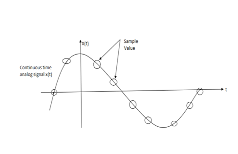
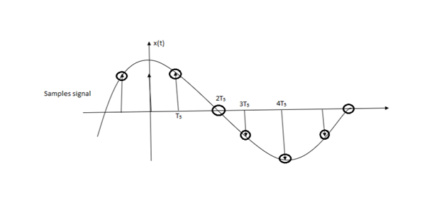
- Let x(t) be a signal with finite energy and infinity duration.
- x(t) be a strictly band limited signal that means it does not contain any frequency compounds above 'W' H2
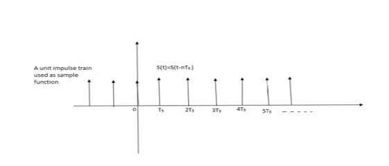
- Let S(t) Be the sampling function it is a train of unit impulses, spaced by a period of Ts second. This sampling function sample the original signal at a rate of 'fs' sample for second therefore 'Ts' represent the sampling period such that
Ts =  = sampling period
Fs =  = sampling rate.
4. Search a train of unit impulses is known as ideal sampling function.
5. Let the sample signal be denoted by xd(t) and as mentioned earlier
Xo(t) = x(t). S(t)
● Aliasing error
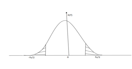
- If the signal x(t) it's not strictly band limited or if the sampling frequency is less than 2w then on error called aliasing or fold over error is observed.
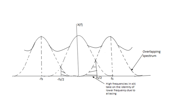
- The adjacent spectrum overlap of fs < 2w
- The signal x(t) is not strictly band limited the spectrum of signal x(t) is show in figure
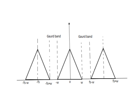
- The spectrum xs(f) of the decorate time signal xs(t) show in figure which is nothing but the sum of X(f) and infinity number of frequency shifted replace of an explained earlier.
- Consider the two replace of X(f) which are centered about the frequency fs and –fs
- If we use a reconstruction filter which its Pam band extending from -fs/2 to +fs/2 then its output will not be an undistorted version of the original signal x(t). Some distortion will be present in the filter output.
- The dispersion accuracy due to the overlapping of the adjacent spectrum X show in figure. Due to this overlapping it is sing that the portions ab the frequency shifted replace r are folded over inside the desired spectrum.
- Due to this full over high frequency in X(t) are reflected into low frequency in Xs(t) this can be understood by comparing the stated portions of the spectrum
● Aliasing - this phenomenon of a high frequency in the spectrum of the original signal x(t) taking on the identity of lower frequency in the spectrum of the sample signal xs(t) is called an aliasing or error.
Due to aliasing seine of the information content in the original signal x(t) is lost in the process of sampling.
Aliasing can be completely eliminated if we take the following action
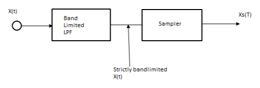
i) Use a band limited low pass filter and pan the signal x(t) through it's before sampling show in figure
Ii) This filter has cut off frequency at fc=w therefore it will strictly band limited the signal x(t) before sampling takes place this filter is also so called as anti aliasing filter or prevails filter.
i) Increase the sampling frequency fs to a great extent i.e. fs >>> 2w
Ii) Due to this even through x(t) is not strictly band limited the spectrum will not overlap
Iii) A guard band is created between the adjacent spectrum as show in fig.

Abnormal conditions and causes of failures in 3 phase Induction motor
The induction motor cannot be considered in isolation on the one side it is connected to the supply possibly through some kind of power electronic controller and on the other side it is mechanically coupled to the load therefore the induction motor is subjected to a large number of faults and abnormal operating condition as depicted in figure
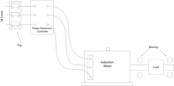
Supply
- Fault on motor terminal
- Unbalanced supply voltage
- Single phasing
- Reduced supply voltage
- Reversal of phases.
Motor
1) Phase faults
2) Ground faults
3) Inter turn faults
Load
- Failure of bearing
- Prolonged overload
- Rotor jam
Starting current
Induction motor draws a very large starting current of the order of 6 to 8 times the full load current is started direct-on-line the amplitude of the starting current maybe comparable to fault current. Therefore the over current protection provided to the motor must be able to discriminate between a genuine fault and an over current due to starting the motor. Hence coordination between the starting characteristic of the motor and the overcurrent relay is required figure shows the starting current superimposed on the thermal capability curve of the motor and the characteristic of an overcurrent relay which might be used for protection of the motor it can be seen from figure that the OC relay characteristic must be above the starting characteristics but below the thermal characteristics of the motor this will ensure that the protective relay does not operate during starting phase the motor but will positively operate when load exceeds the motors thermal capability.
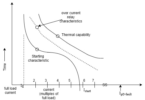
Fig: Starting & Thermal characteristic of Induction Motor
Electrical faults
- Fault on motor terminal
The phase fault current at the terminals of a motor is considerable e larger than any normal current such as starting current or any internal fault current.Hence a high set instantaneous overcurrent relay is recommended for fast and reliable inexpensive and simple protection.
- Phase faults inside one motor
Protection against face false as well as ground force can be provided using either uses for overcurrent relays depending upon the voltage rating and size of motor most motors will be protected by HRC fuses the fusing current should be greater than the starting current off the motor the fuse operating time should be less than the permissible locked rotor time off the motor the locked rotor time is the time for which the rotor can be softly started with full supply voltage applied to stator.
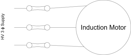
Fig: HRC Fuses for Protection of 3 Φ IM
Big motors which are high voltage motors will need to be provided with an overcurrent protection for increased accuracy of protection as shown in figure the thermal capability of characteristic of the motor should be kept in mind while applying overcurrent protection the OC relay characteristic should be below the thermal capability characteristic as shown in figure
In case of high impedance ground force inside the motor the fault current may happen to be less than the full load current such falls are difficult to detect using overcurrent approach a current balance type of protection characters for such force are explain in next section
In case of big motors whose KVA rating is more than half of the supply transformer KVA rating the current for a 3 phase fault may be less than 5 times the current for locked rotor condition in such cases it is recommended to use percentage differential protection as shown in figure. If the motor KVA rating is less than half of the supply transformer KVA rating overcurrent relays can be relied upon. The logic for this criterion can be explained as follows:
Assume motor is connected to a supply transformer with 8% impedance the maximum fault current at the transformer secondary with an infinite source is
 per unit on transformer base.
The maximum motor starting current in this case is

Where  is the motor impedance.
In order that  must be greater than 0.3 to per unit on the transformer KVA if the motor has a full voltage starting current of six times the full Load then
 on the motor rated KVA base. With a motor KVA of half of the transformer KVA an
  at 0.167 could be 0.333 on the transformer base which is greater than 0.3 to clearly this rule of thumb should only be applied when there is no appreciable deviation from the parameters assumed above
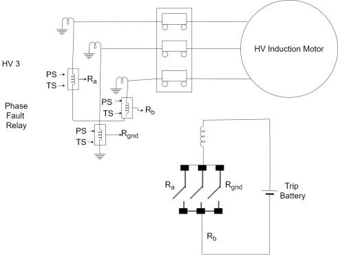
Fig: Phase fault & ground fault protection of HV IM
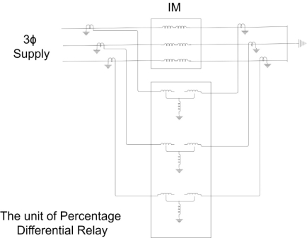
Fig: Percentage differential relay of Protection of 3ΦIM
Ground faults inside the motor
Figure shows an arrangement for detecting high impedance ground force three phase line conductors carrying current to motor form primary of transformer the secondary consists of a pickup coil wound on the core
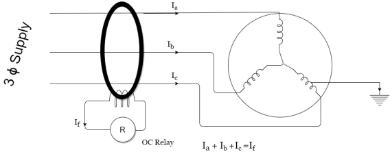
Fig: Earth Fault Protection
When the motor is running normally the instantaneous sum of all the three line current is zero does there is no net flux in the core hence the pickup coil does not have any voltage induced in it now consider ground fault as shown the three line current do not sum up to zero. Thus there is a net primary MMF proportional to the fault current if returning to the supply neutral through the fault but there is does a flux in the CT core. The pickup coil has a voltage induced when can be sent by an electronic circuitry all the pickup coil can be made to drive the operating coil at a sensitive relay.
If an electronic circuit is used to change the voltage developed by the pickup coil the current balance relay described above can be made extremely sensitive and can detect Earth fault currents down to a few tense of milli Amperes very high sensitivity however is likely to cause some nuisance stripping
- 3 phase induction motor protection.
Single phasing protection
- Single phasing means one of the three phases is disconnected from the 3
 supply so that motors two faces are only remain electrically connected this happens due to burning out of one fuse out of three fuses.
 - When single phasing occurs and the motor is running on load the speed of the motor suddenly decreases and motor resist to stop or run slow .
- Hens born stators rotor is overheated due to increase in current in remaining two windings.
- The protection use for single phasing fault are
Thermal overload relays. -: thermal overload relays operate due to increase in current of two phases and drip the circuit.
Single phase preventer -: main parts of the circuit
A) Control coil
B) Negative sequence
C) Contacts
D) N C contacts
E) No contacts
F) Thermal relay
- The preventive circuit is connected in secondary of C T & R Y B lines actors primaries of the C T . The negative sequence filter is connected as shown in figure
- The output of this filter is fed to a level detector. This sends the dripping command to the starter and NC contacts get opened and contracts get opened, stopping the motor as it is disconnected from the supply R Y B .
- This type of preventer is generally used for small medium capacity motors.
Reference Books
- [R1] Badri Ram, D. N. Vishwakarma, “Power System Protection and Switchgear”, Tata McGraw Hill Publishing Co. Ltd.
- [R2] J Lewis Blackburn , “Protective Relaying- Principles and Applications”, Dekker Publications.
- [R3] Prof. Dr S.A. Soman, IIT Mumbai, A Web course on “Digital Protection of power System”
- [R4] A.G. Phadke, J.S. Thorp ,Computer relaying for Power System , Research Studies
- Press LTD, England.(John Willy and Sons Inc New York)
- [R5] Mason C.R., “Art and Science of Protective Relaying”, Wiley Eastern Limited.
- [R6] Arun Ingole, “Switchgear and Protection”, Pearson.