Unit - 5
Transformer Protection
1) Protective equipment for TIF protection includes gas relays which give an alarm on incipient faults.
2) Differential system of protection which gives protection on phase to phase plus phase to ground faults.
3) Other protective relays and surge arresters which give protection to the insulation from high vtg. Survey as.
4) A through fault is one which is began the protected zone of TIF , but fed to the TIF.
5)A Differential protection should not operate for through faults.
6)Internal faults are those in the protected zone of the TIF.
7)These faults can be between phase to –phase and phase to – ground.
8)Incipient fault are initially minor faults causing gradual damage these faults grow into serious fault.
9)Incipient fault includes loose connection in conducting path, sparking small arcing etc.
10) The faults occurring – in power TIF are earth- faults, phase – to-phase faults inter-terms faults and overheating from overloading or from some internal cause such as core-heating.
11) of these the most common are earth-faults inter-turns faults .but the latter develop rapidly into earth faults and therefore only earth faults protection is generally provided.
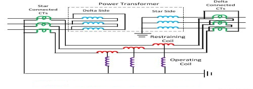
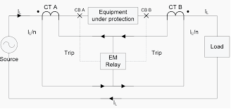
1]The differential protection responds to the vector difference between two similar quantities .
2]In protection of TIF ,CT’s are connected at each end of the TIF.
3]The CT secondary’s are connected to in star or delta and pilot oires are connected between the CT’s of each end.
4]The CT connections and CT ratios are such that currents fed into the pilot wires from both the ends are equal during normal conditions and through faults.
5]During the internal faults such as phase to phase or phase to and,the balance is disturbed .
6] The out of balance current I,-Iz flows through the relay operating coils .
7] To avoid unwanted operation on through faults restraining biased coil are provided in series with pilot wires.
Problems arising in Differential Protection
1] Difference in length of pilot wired on either sides of relays. The difficulty is overcome by connecting adjustable registers to pilot wires. These are adjusted on site to get equi potential points on pilot wires .Taps can be provided on operating coil and restraining coil of relay for adjusting the balance .
2] Difference in C.T ratios due to ratio error difference at high values of SC currents Because of this difference the relay operates for through faults .this difficulty is overcome by using biased differential relay for percentage differential relay In such a relay a restraining coil is connected to pilot wired. The current flowing through restraining coil can be taken as ( )l 2
)l 2
With increase in through current the restraining torque increases too and the current due to CT inaccuracy is not enough to cause relay operation. The characteristics of such a relay is given earlier.
3] Tap changing alters the ratio of vtg.(& currents)between H.V side & L.V side .Differential protection should be provided bias (Restrain)which exceeds the effect of variation in secondary current due to tap changing.
4] Magnetizing current Inrush – when the TIF is energized, initially there is no induced emf ,the condition is similar to switching of an inductive CKt .The resistance being low, a large inrush of magnetizing current takes place .The magnitude of this inrush current can be several times that of load current, The magnitude of inrush current depends on CKt. Condition & vtg.at the instant of switching. Maximum peak values equal to 6 to 8 times the rated current can occur.
Inrush Phenomenon
1]Under normal operating conditions, the magnetizing current is very small.
2] However, when a TIF is energized after it has been taken out of service, the magnetizing inrush current can be extremely large (as large as 10 times full lead current)for a short period (5 to 10 cydes, sometimes as large as 4 to 6 sec.)
3] Since magnetizing current flows through primary wdg,it causes difference in CT’s o/p and make the relay to operate, which is not desirable .
4] There are a number of wages of overcoming the above problem.
5] Firstly, the relay may be provide with a setting larger than the maximum inrush current.
6] Secondary the time setting may be made long enough for the magnetizing current to subside before the relay operates.
7] But for EHV TIF these simple remedies are not incompatible.
8] The third alternative is the use of “Harmonic Restraint Relay”
Harmonic – Restraint Relay :-
1] The operation of the relay because of the magnetizing inrush current can be avoided by using relays with inverse and Definite Minimum Time (TDMT) Characteristics.
2]The magnetizing inrush currents have a high component of even & odd harmonics (about 63% of second harmonic &b26.8% of third harmonic) While harmonic component of short CKt. Current is negligible.
3] The use of these facts is made for restraining the relay from operation during initial current inrush.
4] The harmonic restraint differential relay is sensitive to magnetizing current.
5] The operating coil of the relay carries only the fundamental component of current only, while the restraining coil carries the sum of fundamental and harmonic components.
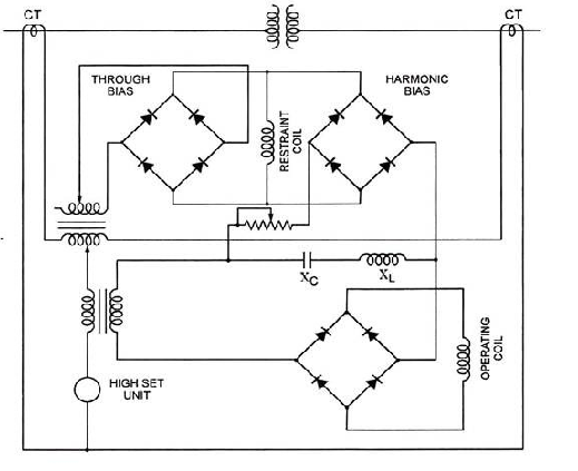
6] The restraining coil is energized by a direct current proportional to wdg.current as well as the direct current due to harmonics.
7] Harmonic restraint is has from a ‘tuned ’CKt (Xc – Xc) that allows only the fundamental operating Ckt.
8] The dc & higher harmonic are diverted into the rectifier bridge feeding the restraining coil.
9] The relay is adjusted so that it will not operate when the harmonic current exceeds 15 % the fundamental current.
10] Both the dc and higher harmonic are of large magnitude during magnetizing inrush.
11] If a fault exists at the instant of energization of TIF .harmonics present in the magnetizing current, mag prevent the operation of relay.
12] This problem can be overcome by providing instantaneous overcurrent relay in the differential CKt which is set above the max. Inrush current but will operate in less than one cycle on internal faults.
Restricted Earth Fault Protection :
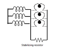
1) A CT is fitted in each connection to the protected and the secondary’s of CT’s are connected in parallel to a relay.
2) Ideally the o/p of the CT’s is proportional to the sum of zero sequence current in the line and the neutral earth connection , if the latter is within the protected zone.
3) For external faults, zero sequence currents are either absent or sum to zero in the line and the neutral earth connection.
4) For internal faults, the sum of zero sequence currents is equal twice the total fault current .
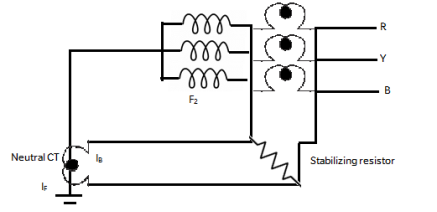
5) When there is an earth faults outside the protective zone say at E1,it causes the currents  &
& in CT secondaries as shown.
6) So the resultant current in earth fault relay is negligible.
7) For an earth fault within the protected zone, say at  ,only current,
  being negligible.
8) Thus current  flow through the earth fault relay.
9) Thus restricted earth fault relay does not operate for earth fault beyond the protective zone of the TIF.
10) For an earth fault near the neutral point of the TIF the vtg. Available for driving earth fault current is small.
11) For the relay to since such fault, it has to be too sensitive and would therefore operate for spacious signals , external faults and switching surges.
12) Hence the relay is set as per practice so as to operate for earth fault current of the order of 15 % of rated wdg current.
13) Such setting protects restricted portion of the wdg hence the name restricted earth fault protection.
14) Stabilizing resistors is connected in series with the relay to avoid magnetizing inrush current and also saturation of CT.
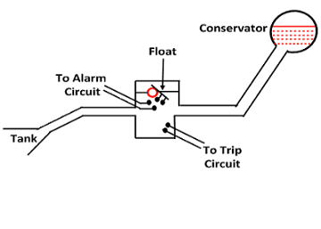
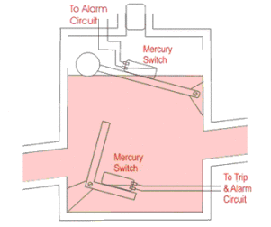
1) The incipient faults in transformer tank below oil level actuate Buchholz Relay so as to give alarm.
2) The arc due to fault causes decomposition of TIF oil.
3) The Buchholz Relay is fitted in the pipe leading to the conservator.
4) The gas get collected in the upper portion of the Buchholz Relay.thereby the oil level in the Buchholz relay drops down.
5) The heat in the Buchholz relay this down with lowering the oil level.
6) While doing so the mercury switch attached to the heat is closed and the mercury switch closes the alarm circuit
7) Thereby the operator know that there is some incipient fault in the TIF .The TIF is disconnected as early as possible and the gas sample is tested.
8) The testing of gas gives clue regarding the type of insulation failure.
9) Buchholz relay gives an alarm so that the TIF can be disconnected before the incipient fault grows into a serious one .
Limitation of Buchholz Relay :-
1) Only faults below oil levels are detected.
2) Setting the mercury switch connect be too sensitive otherwise there can be a false operation by vibrations, earthquake mechanical shocks to the pipe, sitting of birds etc.
3) The relay is slow, minimum operating time is 0.1 sec ,Avg. Time 0.2 sec , such a slow relay is unsatisfactory.
The flux and the applied vtg. In a TIF are related through the following expression.
V = 4.44 
Where ,
V = rms value of vtg.
f = frequency
N = No.of turns in wdg.

1) Whenever there is on over –vtg (freq. Remaining constant) the TIF core is subjected to a higher value of flux in order to be able to support the higher applied vtg.
2) Any increase in applied vtg. And the consequent increase in flux density, drives the TIF deeper into saturation.
3) The TIF therefore draws an excessive magnetizing current. Hence the condition is described as “Over –excitation”.
4) This considerably increases the core losses giving rise to overheating of the TIF.
5) Further, saturation of the core causes the flux to flow into adjacent structures, causing high eddy current losses in the core and adjacent conducting material.
6) Such an operating condition cannot be allowed to continue for long and the TIF should be tripped if there is a prolonged over – excitation.
7) It can be easily seen that over – excitation can also occur in case low – frequency operation of TIF at rated vtg.
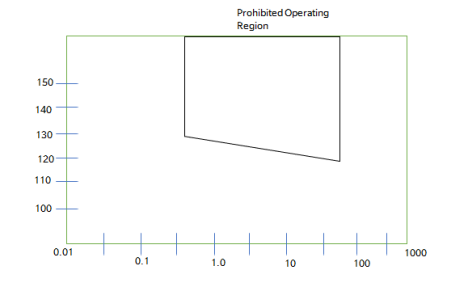
8) Therefore , to keep the working flux within the permissible limits, the VIF ratio must not exceed the permissible limit.
9) For e.g. a TIF designed for a percentage Vtg limit of 125 % at rated freq. Will experience over – fluxing whenever the vtg exceeds 125 % at rated freq.
10) Thus over-excitation can be detected by measuring the VIF ratio by it is also called volts/Hz relay.
Numerieas TIF Differential Protection:-
1) The idea is to estimate the phases value of the current on both sides of the TIF and find the phases difference between two.
2) If the magnitude of this difference is substantial an internal faults is indicated and the their signal should be issued .
Algorithm For % diff. Relay will consist of following steps.
1) Read % bias B and minimum pick-up Ipu.
2) Read ip samples -> Estimate phasor Ip using any technique.
3) Read is sample -> Estimate phasor Is using any technique.
4) Compute spill current Ispill = Ip – Is
5) Compute circulating current Icir = 
6) If Ispill > (BIcir + Ipu) then trip ,else restrain
II) Generation Protection –
6 Abnormal Conditions –
1) External Faul1ts-
The external faults such as faults on bus – bars are not covered by generators protection zone. Hence differential protection of generator done not responds to external faults.
The over current and earth fault protection of generator provides back – up protection to external faults. While primary protection as provides by the protective system of respective equipment (e.g. Rus – bars, x-lines)
2) Thermos overloading –
Continued overloading may increase the wdg. Temperature to such an extent that the insulation will be damage and its useful is reduced.
Temp. Rise can also be caused by failure of cooling system.
3) Unbalance Loading –
Continue unbalanced loads , equal to or more than 10 % of the rated current cause dangerous heating of the cylindrical rotor in turbo – generators.
Unbalance loading on gen can be due to
- Unsymmetrical faults in the system near the generating station.
- Mal – operation of a C.B near generating station, the 3. not being cleared.
Stator Winding fault –
Stator winding faults involve armature winding and must therefore be cleared quickly by complete shutdown of generator.
The stator, fault includes.
a) Phase – to – phase faults
b) Phase to earth faults.
c) Stator inter – turn fault
a) Phase to Earth Fault –
These faults normally occur in the armature slots. The damage at the point of fault is directly related to the selected neutral earthing resistor, with fault current less than 20 A , negligible burning of the iron core will result if the machine is tripped within some seconds.
If however, the earthing resistor is selected to pan a much larger earth- faults current (> 200A) severe burning of the stator core will take place. In the case of high earth. Fault currents it is therefore normal practice to instars a C.A in the neutral of the generator in order to reduce the total fault – clearance time.
b) Phase to Phase fault:-
Short circuit between the stator wdg very rarely occure because the insulation in a 3 slot between coils of different phases is at least twice as large as the insulation between one oil and the iron are.
A fault of this nature causes severe arcing with high temp, melting of copper and risk of fire if the insulation is not made of fire – resistant , non-flammable material.
c) Stator Inter – turn Faults :-
Short circuit between the turns of one coil may occure if the stator wdg.is made up of multiturn coils. Such fault may develop owing to incoming current surges with a steep wave-front which may cause a high vtg.(L di/dt) across the turns at the entrance of the stator wdg.
9
4) Field winding Faults –
Rotor faults include rotor inter-turn fault and conductor to earth faults. These are caused by mechanical & temp. Stresses.
The field system is normally not connected to the earth so that a single earth fault give rise to any fault current.
A second earth fault will short circuit part of the wdg. And may thereby produce an unsymmetrical field system, giving unbalances force on the rotor .such a force will cause,excess pressure on bearing & shaft distortion ,if not cleared quickly.
5) Over Voltages :-
a) Atmospheric surge voltages are caused by direct lighting stroke to the line in the H.V.system.
b) Switching Surges –Switching operation may cause relatively high transient over voltage if restricting occurs across the contact of C.A.
6) Other abnormal Conditions –
a) Loss of Synchronism
b) Wrong Synchronization
c) Asynchronous Running Without excitation
d) Local overheating
e) Leakage in Hydrogen ckt.
f) Moisture in the generator wdg.
g) Oxygen in pure water ckt.
h) Over speeding
i) Motoring of generator
j) Vibrations.
k) Excessive Bearing Temp.
l) Bearing Current
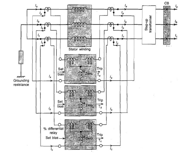
1) Phase& ground faults on the stator armature winding can be easily detected by a conventional percentage differential protection shown in fig.
2) This type of scheme is also known as longitudinal differential scheme.
3) The Longitudinal differential scheme caters for phase as well as ground faults on the stator wdg.
4) However, it is unable to detect the inter – turn faults between turns of some phase
Transverse Differential Protection
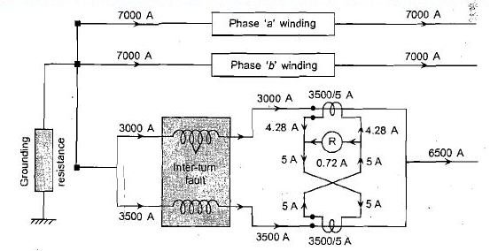
1) In order to apply this type of protection , a special type of split winding is required as shown in fig.
2) Current in each parallel seation is now compared with that in the other seation.
3) If there is an inter – turn fault in one- section, then the currents will differ and flow as spill current through OC relay as shown in fig.
4) In fig. Only the wdg with the inter –turn fault is shown in detail.
5) The half of the wdg.in which there is an inter – turn fault is shown to carry 300A whereas the heating half carries 3500A.
6) The current entering the phases wdg as a whole is 6500A which is the same as that leaving it.
7) Therefore, longitudinal differential relay would be incapable of detecting such fault.
8) However, because of the splitting of the wdg. And transvers connection of the CT.s there is a split current of 0.72A in the transverse differential relay. Thus a setting of 0.5 A will be enough to detect such an inter –turn fault.
Neutral Earthling –
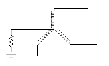
1) The resistance R limits the earth – fault current .If R is too small(Solid earthling)earth fault currents are too large hence such a method is not used for large machines solid earthling is limited to machines upto 3.3 k.v.
2) For resistance earthling the resistance R is such that full load current passes through neutral for a full line to neutral vtg.
3) Medium res. Earthling is commonly used on generator. TIF units.The earth fault current is restricted to about 200A for full line to neutral vtg. For a 50MW unit.
4) In high resistance earthling max. Earth-fault current is of the order of 10A. Such earthling is used for distribution TIF and generator TIF units.
5) With higher neutral res. The earth faults current is reduced, hence lesser percentage of wdg. Is protected by the restricted earth fault protection.
6) Assuming R is the resistance in neutral connection to the earth and the fault current for line to ground fault is equal to full load current of the generator or TIF. The value of impedance inserted in the neutral to earth connection is given by.
R = 
Where, R= Impedance in ohms. Betn neutral & gnd.
V= Line to neutral vtg
I = Full load current of larger m/c .
7) If a relay setting of 15% is chosen this affords protection of 85% of the wdg of largest M/C while a greater % of wdg . Of smaller m/c running is protected with large m/c.
% of wdg unprotected = 
R= ohmic value of inpeance
IO= Minimum operating current in primary of CT
V= line to neutral vtg
8) If 15% of relay setting is used ,Io is 15% of fuel load current of the m/c
PROBLEMS: -
1) A Generator is provided with restricted earth feat protection. The rating are 1.1kv ,500KVA. The percentage of vdg protected against phase to ground fault is 80% the relay. Setting such that it trip for 25% out of balance. calculate the resistance to be added in neutral to ground connection
->
V = 100=63.40V
I= = 262A
Io= 262× =65.5 A
% of wdg unprotected =  ×100
×100
.: 20 = ×100
×100
Hence the resistance to be added in the neutral connection is,
R= 

2) A 11KV 70MVA , Alternator is provided with differential protection, the percentage of wdg, protected against phase to ground fault is 75% the relay is set to operator when there is 20% out of balance current determine the value of the resistance to be placed in the neutral to ground connection.
-> V= ×1000 = 6350V
I =  =3674A
Io=3674× =734A
=734A
% Of wdg unprotected = ×100
×100
.: 25=  ×100
×100
.: R =

3) The neutral point of a 10000v alternates is earthed through resistance of 10Ω the relay is set to operate when there is an out of balance current of IA, The CTS have a ratio of 1000/5 what% of wdg is protected against fault to earth and what must be minimum value of earthing resistance to give 90% protection to each phase wdg.
->
Out of balance current in pilot wire is AMP. Corresponding current in CT primary will be,
1× =200A
=200A
Hence current IO for which the relay operate is 200A
% of winding unprotected,
= ×100
×100
= ×100
×100
= =34.8%
.: % of wdg protected =100-34.8=65.2%
Resistance to get 90% of wdg protection
Io =
.:R

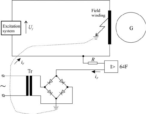
1) The rotor carriers the field wdg. Which is kept isolated from ground
2) Neither the +ve or the -ve terminal of the dc supply is grounded.
3) Thus, and ground fault on the rotor field wdg. Does not affected the working of alternator.
4) However, a sub -sequence fault would cause a section of the rotor wdg. To be short circuited giving rise to a secondary flux which opposed. The main flux in the proximity of the shorted turns causing distortion in the distribution of main flux.
5) The flux will get concertation on one pole but dispersed over the other and intervening surfaces.
6) The resulting a segmometry in the electromagnetic force will cause severe vibration of the rotor.
7) In the height of the above, the vcm first fault on the field winding must be detected and the set triples in a controller manner.
8) An arrangement for rotor earth Fault detection and protection is shown in fig. Where in an external vtg. Source is superimposed on the rotor ckt.
9) This external vtg source is grounded so that very rotor earth Fault causes a dc Fault current to flow which is easily detected by an dc relay.
Abnormal Operating Conditions, inter turn fault
1) A Generator can must be consider in isolation because of a very large number of other equipment connected to it.
2) Even though there is no electrical Fault in the generator, if one of its associated equipment develops a Fault, there it has serious implications for the generators.
3) Every auxiliary equipment connected to the generator is likely source of trouble.
4) There are a large no of possible Fault as well as combination of Faults, on this equipment.
5) Where there is no direct electric Fault on generator, but one or more its associates equipment develops a Fault or an abnormality may lead to an abnormal operating condition which may or may not be serious.
6) However, all abnormal operating conditions need to be detected as quickly and sensitively as possible so that the corrective action can be taken and a possible shutdown obverted or anticipated.
7) Following are some abnormalities.
1) If there is an unbalance loading of the generator than the stator current have a negative sequence component.
2) The stator field due to these negative sequence current, rotates as synchronous speed but in a direction opposite to the direction of the field structure on the rotor.
3) Thus, the negative sequence stator armature mmf rotate at a speed - Ns while the rotor field speed is +Ns
4) Therefore, there is a rotative velocity of 2Ns between the two.
5) This causes double frequently currents of large amplitude to be induced in the rotor conductors & iron.
6) Therefore, both the current we as the histories losses increased due to their double frequency induced currents in the rotor.
7) Thus if the stator carries unbalanced current then it is the rotor which is overheated
8) How long the generator can be allowed to run under unbalanced loading depends upon the therefore with stand capacity of the mc , which in turn depends upon the type of cooling system adopted .
9) The rate of heat generation is proportional to IR while the heat energy is proportional to IZ Rt, where Z2 Is time & I2 is negative sequence current.
10) Since. The capacity of a particular m/c to safely dissipate energy , is limited to a certain value , we can write,
- IZ2 RT=K
11) Thus, the current time characteristics can be written as.
- T≤

12) This characteristic is similar to that of the extremely inverse time over current relay
13) Thus an inverse type of over current relay which is fed with the negative sequence component of stator current give protection against unbalance loading of generator.
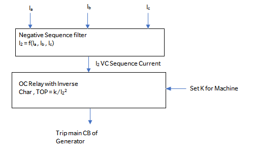
14) If we could, some how extract the negative sequence component of the stator current then the protection against. Unbalanced loading can be implementer by applying the inverse time oc relay as shown in fig.
1) Consider that a fibro alternator is supplying it is rator real electrical power pe to the grid
2) Its mechanical I/p pm IS Nearing equal to Pe (except for the losses) and the mc runs at consistence synchronous speed Ns
3) Now considered that due to some fault the generator is tripped and disconnection from the grid.
4) Thus pe become zero, however the mechanical I/p pm can’t be suddenly reduced to zero
5) Therefore, we land up in a situation where the generator has full i/p much power but no o/p electrical power
6]. This would cause the m/c to accelerate to dangerously high speed, if the mech. i/p is not quickly reduced by the speed – governing mechanism.
7]. The protection against such an eventuality can be provided by sensing the over – speeding and taking steps such as operating the steam valve so as to stop steam i/p to turbine.
8]. The speed – governing mechanism or the speed governor of the turbine is basically responsible for detecting this condition.
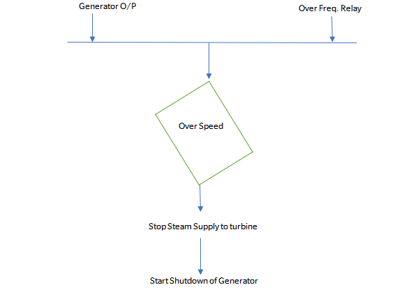
9]. The over – speeding can also be detected either by an over – freq relay or by monitoring the o/p of the tach generator mounted on the generator shaft.
The logic of protection against over – speeding is shown in fig.
There are several possible causes due to which field excitation may be lost.
1]. Loss of field to main exciter.
2]. Accidental tripping of the field breaker.
3]. Short ckt in the field wdg.
4]. Poor brush contact in the exciter.
5]. Field C.B. Latch failure.
6]. Loss of AC supply to excitation system.
1]. The generator delivers both real as well as reactive power to grid.
2]. The real power comes from the turbine while the reactive power is due to the field excitation.
3]. Consider a generator delivering the complex power, S = Pe + jQe to the grid.
4]. Corresponding to real power Pe there is a shaft mechanical power i/p Pm and corresponding to reactive power Qe there is the field current If as shown in fig.
5]. Now, consider that the field excitation is lost while the mechanical i/p remains intact.
6]. Since the generator is already synchronized with grid, it would attempt to remain synchronized by running as an Induction Generation
7]. As an Induction Generator, the machine speeds up slightly above the synchronous speed and draws it’s excitation from grid.
8]. Now there are two possibilities Either the grid is able to meet this reactive power demand fully or meet it partially.
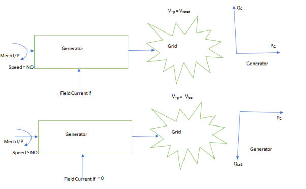
9]. If the grid is able to fully satisfy this demand for reactive power, the machine continues to deliver active power of Pe MW but draws reactive power of QLOE MVA and there is no risk of instability.
10]. However, the generator is not designed as an induction m/c, so abnormal heating of rotor and overloading of the stator wdg will take place.
11]. If the grid were able to meet the reactive power demand only partially then this would be reflected by a face of the generator terminal vtg.
12]. The generator would be under excited. There are certain limits on the degree to which a generator can be operated within the under – excited mode.
13]. Therefore, the operation in case of loss of excitation must be quickely detected and checked to avert any shutdown of Gener.
14]. The simplest method by which loss of excitation can be detected is to monitor the field current of the generator.
15]. If the field current falls below a threshold, a “ Loss of field Signal “ can be raised.
1]. During normal steady – state operation, the impedance seen from the stator terminals i.e. the apparent impedance lies in quadrant I, of the R – X plane as seen in fig.
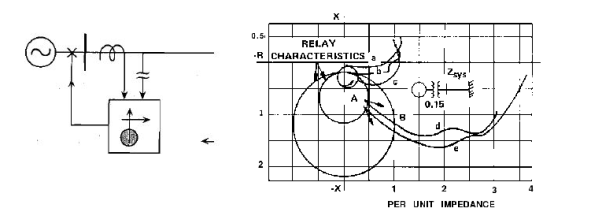
2]. After the loss of excitation, the apparent impedance enters quadrant IV.
3]. The exact locus of the apparent impedance and the rate at which it is traced out depends upon the initial complex power that was being delivered by the generator.
4]. If the initial power o/p was high then the locus is traced out quickly.
5]. However, if the initial power o/p was low then the locus is traced out rather slowly ( taking upto a few seconds ).
6]. In order to keep the generator online as long as it is safe, the generator may not be instantaneously tripped in case of loss of excitation.
7]. As soon as loss of excitation is detected by the relay, an alarm may be sounded and an attempt may be made to see if excitation can be restored.
8]. A mho type distance relay with offset characteristics may be used for protection against loss of excitation.
9]. The offset is by an amount equal to Xdlz. The impedance setting of the relay is | Xd | at an angle of -900.
10]. In order to give time for change over to the standby excited by the control circuitry, the relay operation can be delayed by about 0.5 – 3.5.
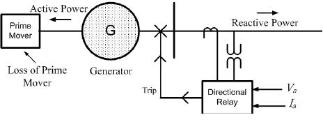
1]. In case of loss of prime mover, i.e. loss of mechanical i.e. the m/c continuous to remain synchronized with the grid, running as a synchronous motor.
2]. The m/c now draws a small amount of active power ( compared to it’s rating ) from the grid in order to drive the turbine and meet the losses taking place in the machine.
3]. At the same time, the m/c supplies reactive power to the grid since it’s excitation is intact.
4]. Running in this mode is not harmful to the generator, but is definitely harmful to a prime mover like a steam turbine.
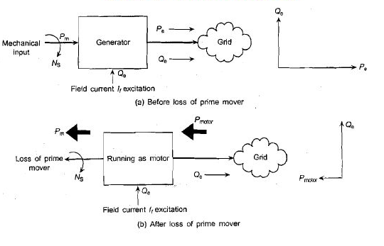
5]. Normally, loss of steam supply to the turbine caused loss of prime mover.
6]. When the m/c runs as a motor, there is a churning of trapped steam in the turbine causing objectionable temperature rise and damage to the blades.
7]. Therefore, loss of prime mover needs quick detection followed by tripping of generator.
8]. When the prime mover is lost, the Gener starts drawing real power from the grid, supplying the reactive power to the grid as before.
9]. The real power drawn from the grid is quite small compared with the generator rating.
10]. The generator draws real power which is just enough to meet the losses and the load put on it by the turbine.
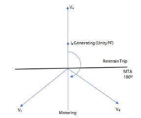
11]. Hence, the magnitude of stator current is smaller than when it was generating but the stator current undergoes 1800 phase shift as shown in fig.
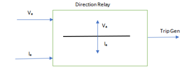
12]. This suggest that if we use a directional relay with an MTA of 1800 ( using generator phase angle conventions ) as shown then it would detect the loss of prime mover as the current phasor would reverse and enter the trip region.
13]. However, the magnitude of this reversed current phasor is quick small compared to the forward current as the generator draws just enough real power to meet the losses and drive the turbine.
14]. Hence the directional relay for detecting the loss of prime mover needs to have a high degree of sensitivity compared to directional relay used for over – current application.
III]. Bus – Bar Protection :-
6 Differential protection of Bus – Bar :-
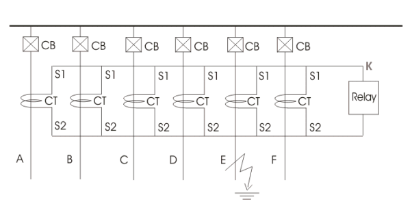
1]. The differential protection is a wide term applied to protections which responds to vector difference between two or more similar electrical quantities.
2]. A simple method of bus – bar protection is by comparing the vector – sum of currents entering and leaving the bus – zone.
3]. In absence of internal fault, the vector sum of currents entering the bus – zone is equal to the vector sum of currents leaving the bus zone. In other words,
∑In = I1 + I2 + I3 + ….. + In = 0
Where I1, I2….. In etc are currents in the circuit connected to the bus – bar.
4]. During internal fault the vector sum of currents in the circuits connected to bus – bar is equal to fault current i.e.
I1 + I2 + I3 + ….. + In = If
The out of balance current flows through the fault.
5]. In differential protection of bus – bar, CT’s are connected in each circuit connected to bus bar.
6]. The secondary’s of these CT’s are connected in parallel with due consideration to polarity and phase.
7]. The relay coil is connected across the pilot wires in such a way that the summation current of secondary’s passes through the relay.
8]. Referring to the fig, the normal condition or external fault, the summation of secondary currents, ∑ in = 0
For internal faults ∑ in≠ 0
∑ in flows through relay coil.
Selection of CT’s for Bus – Bar protection
1]. In the protective scheme requiring close balance of secondary currents in various phase circuits the CT ratio error should be low.
2]. The CT’s for such protection should be selected such that the balance is maintained for maximum through faults current in primary of any of the phase under transient conditions and also steady conditions.
3]. The large power system have a large X/R ratio.
4]. The d.c. Component of fault current decays slowly and CT cores remain saturated for longer duration ( 5 to 30 ms ) since CT core gets magnetized with unidirectional component of fault current.
5]. The residual flux present in the core has a direction which depends on the instantaneous condition at the end of earlier switching.
6]. The residual flux also depends on the remanance of CT core material.
7]. The total flux is caused by dc component, residual flux, a.c. Component.
8]. If residual flux is in same direction as that of d.c. Component, the core may saturate and harmonic spin current will flow through the relay coil.
9]. The following aspects are considered while selecting CT’s for differential bus – zone protection.
i]. Use of identical CT’s in which saturation occurs at large S.C. Currents.
Ii]. Increasing C.T. Ratio ‘ n ’ so as to decrease the ratio of ‘ Ish / I1 ’, where Ish is fault current and I1 is rated primary current.
Iii]. Selecting as large core as economically & technically suitable thereby increasing limiting value of secondary current ( in ) for saturation of core.
Iv]. Reducing the burden on CT’s by using pilot wires of lesser resistance static relays.
v]. Use of intermediate CT’s with gapped core.
10]. When an internal bus fault occurs, the magnitude of the fault current and it’s d.c. Component may be so large that the line CT’s saturate within 1.4 ms.
11]. In such cases it is essential that the bus differential protection operates & seals in within 2ms i.e. prior to the saturation of the line CT’s.
12]. This high speed is necessary because when a line CT saturate it’s o/p e.m.f. Tends to drop to zero.
High Impedance Differential Relay
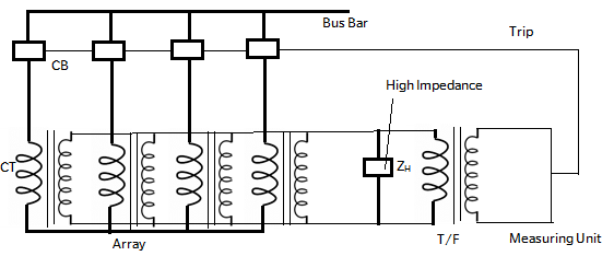
1]. This relaying is based on differential principle.
2]. During normal condition the vector sum of currents in the array is zero. During fault on bus – bar the balance is distributed.
3]. The out of balance current ‘ I ’ flows through the high impedance ZH producing vtg drop VZH.
4]. This vtg is supplied to relay measuring unit M through T/F T.
5]. During fault on bus – bars the trip ckt of all the C.B. Are closed by the same relay, the bus – bar is rapidly dis – connected.
6]. If the relay measuring system responds to vtg drop instead of circulating current, the saturation of one of the CT’s does not cause instability of protection.
7]. During external fault, one of the CT’s may saturate.
8]. Thereby, it’s o/p will be reduced and the vector sum of secondary currents will not be zero.
9]. The resultant unbalance current would cause the relay operation.
10]. However, the vtg drop across the CT under saturated condition will be limited by the IR drop in it’s secondary, IR drop in leads which is relatively low.
11]. However, the vtg drop across secondary of CT does not increase but approaches to zero under saturated condition. Hence VZH reduces.
12]. However, during internal bus – fault all the secondary’s will be feeding the current into the impedance ZH. Hence vtg drop VZH increases and this increase is sensed by the relay.
Reference Books:
- [R1] Badri Ram, D. N. Vishwakarma, “Power System Protection and Switchgear”, Tata McGraw Hill Publishing Co. Ltd.
- [R2] J Lewis Blackburn , “Protective Relaying- Principles and Applications”, Dekker Publications.
- [R3] Prof. Dr S.A. Soman, IIT Mumbai, A Web course on “Digital Protection of power System”
- [R4] A.G. Phadke, J.S. Thorp ,Computer relaying for Power System , Research Studies Press LTD, England.(John Willy and Sons Inc New York)
- [R5] Mason C.R., “Art and Science of Protective Relaying”, Wiley Eastern Limited.
- [R6] Arun Ingole, “Switchgear and Protection”, Pearson.