Unit – 6
Transmission line protection
- Feeder protection.
- Time graded protection.
- Protection of radial feeder.
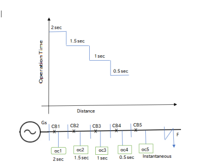
- The main characteristics of a radial system is that power can flow in one direction only from generator for supply end to the load end
- It has the drawback that continuity of supply cannot be e maintained at the lower end in the event of faucet.
- In redial system when number of feeder are connected in series show in figure it is desired that it the smallest possible path of the system should be off.
- This is conveniently achieved by employee time graded protection.
- In this system the time setting of over current relay is adjusted in such a way that Feeder the relay from generating station lesser the time of operation.
- When faucet accuns on the line for side SS4 the relay OC5 corporate first and not any other i.e the time required to operate OC5 should be less than that required for relay OC4.
- Similarly the time required to operate the relay OC4 must be less than that required for OC3 and so on.
- This show that the time setting required for relay most be properly graded.
- The minimum interval of time which can be allowed for the tube adjacent C.B. Depends on its own elearance time plus a small time safety margin.
- With normal C.B in use minimum time between adjacent breakers should be about 0.4 sec.
- The time setting for relay OC1, OC2, OC4, OC5 will be 2.0 sec. 1.55, 15, 0.55
- Drawbacks.
- Time lag is to be provided which is not desirable on short circuits.
- This scheme is suitable for radial feeders with supply at one end only; not for ring mains or interconnected lines.
- It is difficult to coordinate and requires changes with the addition of loads.
- It is not suitable for important long distance transmission lines where rapid fault clearance is necessary to ensure stability of the systems.
B. Protection of Parallel Feeders:
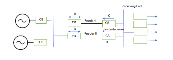
- For important installations continuity of supply is a matter of vital importance and at least two lines are used and are connected normally in parallel so as to share the load.
- These lines may or may not run on the same towers or the same right of way.
- Special means are available for protecting such parallel feeders.
- In the event of a fault occurring, protective device will select and isolate the defective feeder while the other instantly assumes the increased load.
- The simplest method of obtaining such protection is by providing time-graded overload relays with inverse time characteristic at the sending end and instantaneous reverse power or directional relays at the receiving end.
- When heavy fault or short circuit occurs on any one feeder, say at F on feeder No. II, the power is fed into the fault from the sending end as well as from the receiving end bus-bars.
- The direction of power flow will be reversed through the relay on D, which will open.
- The excess current is then confined to B until its overload relay operates and trips the circuit breaker, thus completely isolating the faulty feeder and supplying power through healthy feeder.
- This method is not satisfactory unless the fault is heavy and reverses the power at D.
- Hence differential protection in addition to overload protection must be provided to both ends of the parallel feeders.
Protection of Ring Main System:
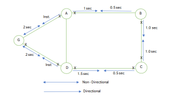
- An elementary diagram of such a system is shown in Fig. Where G is the generating station and A, B, C and D is substations.
- At the generating station, the power flows only in one direction i.e., away from the bus-bars so non-directional time-lag overload relays are used.
- The time-graded directional relays are used at both ends of the substation and they are set so that they will only trip when an overload flows away from the substation which they protect.
- Going round the ring in the direction GABCD; the relays on the farther side of each station are set with decreasing time lags; for instance at generating station 2 seconds at stations A, B, C and D 1.5 seconds, 1.0 second, 0.5 second and instantaneous respectively.
- Similarly going round the ring in the opposite direction, the relays on the outgoing sides would be set as follows:
Generating station G = 2 seconds; substations D = 1.5 seconds; C = 1.0 second; B = 0.5 second and A instantaneous.
6. Now remembering that, the reverse-power relays are set so as to operate only when power flows away from the substation at which they are installed, a study of the diagram will make it clear that a short circuit occurring at any point on the system will cause only the two immediately adjacent circuit breakers to operate.
7. If a fault occurs at point F, the power is fed into the fault through two paths ABF and DCF. The relays to operate are that between substation B and fault point F and substation C and fault point F.
8. Thus fault on any section will cause the relays on that section only to operate and the healthy sections will be operating uninterruptedly.
- Current graded potential
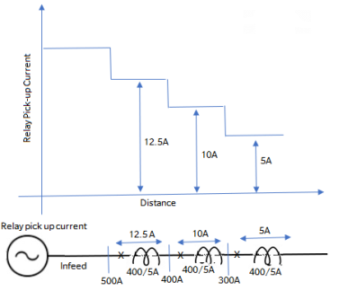
- It is based on the fact that the s.c. Current along the length of the protected circuit decrease with the increase in distance between the supply and fault current.
- If the relay are who operate at a progressively fire Karan to words the supply and then drawback of long time delay occurring in graded time legs system can be partially overcome. This is known as current grading.
- Simple current graded protection scheme applied to a redial feeder is show in figure.
- It consists of a high set O/C relays at A,B,C with setting such that relays a would operate for fault between A and B the relay at B for faults between B and C and the relay at C for fault beyond.
- The current setting diminished progressive from the supply and to the remote end of sinc.
In practice however this protection scheme poses same difficulties which are given below.
- The really cannot differentiate between fault which are very close to you but are on each site it of B i.e a fault is very near to station B in section BC the relay at A may feel that it is in section AB because there may be very little difference in the fault current and the relay do not disseminate between the fault in the next section and the end of first section.
- The difference in the fault current would be extremely small.
- The magnitude of fault current cannot be accurately determined.
- The accuracy of the relay under transistor condition is likely to be different.
Hence for discrimination the relay are set to pocket only e part of the line usually got. For this region current grading alone cannot be employed and this protection system should be supplemented by time graded IDMT relays.
2. The fault current are different for different types of fault and so certain difficulty is experienced relay setting.
3. For ring mains parallel feeder, interconnected system where power can flow to be fault from other direction system without direction control is not suited.
Ii. transmission line protection.
Introduction - to distance protection of H.V + L HV.
- Distance relaying is considered to protection of transmission lives where the fine lake cannot be permitted and selecting can not be obtained by over current relaying distance protection is used for secondary line and main line.
- Distance really measure the ratio V/I at relay location which gives the measure C.
- The impedance of a fault loop professional to the distance between the relay location and the fault point.
- For a given settings the distance relay picks up when impedance measure by it is less than the set value.
- Hence it protect a certain length of line hence it is called distance relay.
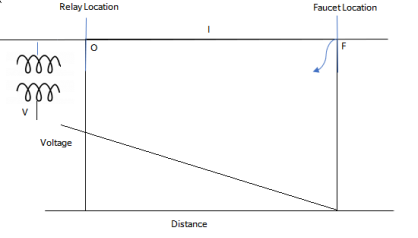
6. Considering zero fault impedance the vtg. At fault point will be zero.
7. The vtg at relay location 0 will be equal to the vtg. Drop along the length CF, where same current I is flowing in the line at 0 upto F
8. If fault had accrued near 0, the vtg. At 0, would be different current would be more because of the reductions in the impedance.
9. If fault accrued away from 0, the voltage at 0 would be less and current would also be less.
10. In distance relay the ration V/I is measured. The current gives operating torque and vtg gives restarting torque.
11. Hence for value of Z above certain settings the relay doesnot operate
12. Hence it protects only a certain length of line equivalent to its imp setting.
13. Keep following types of distance relays are used for principle of measurement
- Plain impedance relay.
- Direction impedance relay
- Mho type distance relay
- Reactance type distance relay.
- Plane impedance e protection.
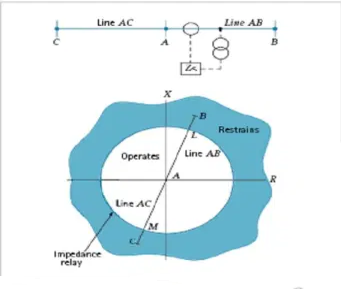
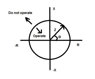
- The plain impedance relay does not recognize the direction in which the fault has accrued relay id non directional (fig a).
- Hence it will operate for all fault along the line BC and also along BA provided the impedance measured by relay ZB is less than the setting.
- The relay unit can be high speed or with time increasing with measured impedance.
- The relay will not only operate for fault on selection BC but also fault in section AB and fault on bulbar in section B.
- Therefore discrimination between fault on neighboring section it's not possible with plain impedance.
- Plain impedance relays has three major disadvantage.
- Selectivity can not be obtained as it operate for fault on either sites circle covers on four sector.
- As it measures resistance and reactance it is affected by resistance of resistance of transmission line.
- It is affected by power swings (fluctuations of reactive power) as the (i) was characteristic covers a large area on every side of centre wing point come within circle.
7. Bet fig a for faults near C in the line BC the relay at B cannot accurately discriminate between in CD and fault in BC.
8. The fault resistance will be e seen by relay as extension of line length there by the set for protecting line BC will not operate for fault very near C this is called under reach.
9. Fault resistance is a horizontal line segment cn R-X diagram
10. For a fault near C fig c3 search segment will take measured point beyond the circle therefore the relay will under reach.
11. It is a sited practice to set the reach of first zone of distance relay to cover any e about 85% of protected line impedance (fig c).
- Direction Impedance relay.
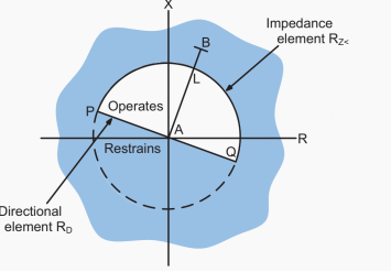
- For achieving discrimination between for word and near fault the directional impedance relays are used.
- Directional impedance protection acts only for fault in forward direction.
- The directional impedance relays ZB does not operate air fault in zone BA and for fault on busbar B.
- Directional impedance relay combined the direction element and impedance measuring element in a single case.
- The vtg supplied to the directional element is taken from the two phases from which current is not taken.
- There by the function at directional element is not affected by drop of vtg.
- Directional impedance relays are protected for phase fault projection of line moderate lengths.
- Reactance Relay.
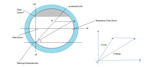
- The main advantage of Reactance Relay is that is not affected by fault resi.
- The characteristics of plain Reactance Relay is a line parallel to R-axis in R-X plane.
- However the reactance relay is not used by itself its generally use along with Mho relay or off set Mho relay
- Suppose reactance relay is use along with Mho starting relay show in figure the reactance relay measured reactance upto fault point.
- The vtg drop due to air (AB) does not affect the measurement as air point in AB are in operating region.
- Hence such relay are used for protection of short line having current less than 20 KA such line the effect of fault res Is prectominant.
- In case of long lines the effect of are resistance is negligible.
- Mho relay / admittance relay
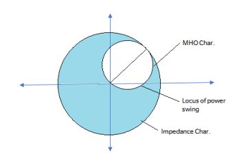
- Mho characteristics is a circle passing through origin of R-X diagram. Mho relay preferred for phase fault relaying of long particularly where serve synchronizing power surgery can accures.
- Comparing the impedance characteristics (for protecting line AB) the the Mho characteristics required very much len area.
- Hence Mho relay can remain inoperative during power swing on HV line to a greater extent than impedance relay.
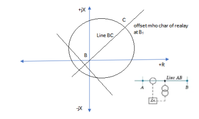
- Pilot wire protection.
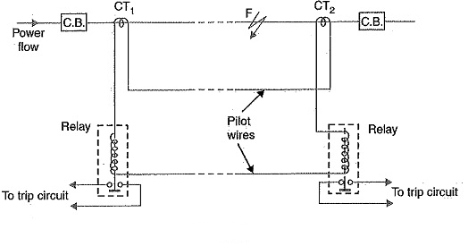
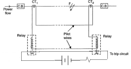
- The different circulating current protection principal can be e readily applied to feeder protection
- Two circuits are connected in each protected line one at each end.
- Under healthy external fault condition the seanday fault current are equal and circulate in pilot wire.
- Relay is connected between equipment point of pilot wires.
- For external fault and normal condition the different current I1 - I6 at two C.T is zero and relay does not operate
- During internal fault this balance is disturbed and different current flow through the relay operating coils.
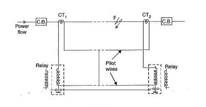
- The C.B at two ends separate by a long distance there is a need to have relaying going at each end associated C.B
- In line protection fig. A relaying point fault in the middle CT the line this means added difficulties
- To solve this problem this circuit is modified figure B. By providing two relays the circuit each end.
- Any other method is by using split pilot principle which use three core cable pilot figure C.
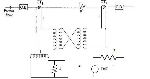
- Piolt wire relaying suing vtg balance
- In this method the secondary current are replaced by our converted to an equivalent voltage source of fairly low impedance.
- The equivalent at two ends are compare as show in figure d
- For heatly condition no current flows through the relay coils.
- During internal fault current circulates through relay coils.
- Vtg balance system is basically a differential system.
- Effect of Arc resistance.
- When planning impedance dependent protection scheme particular attention must be paid to the influence of the arc resistance on the loop impedance.
- This resistance has abmic nature and increase the ckt imp of the short circuit loop.
- This falsified the measurement of impedance by the protection equipment as regards both magnitude and phase relations.
- Allowance must be made for the effect of are res. When setting the protection equipment.
- The resulting tripping characteristics represent modified value between the impedance and conductance measurement.
- Modern distance protection relays include provision for matching the degree of arc compensation to the short circuit angle of the line depending on the application.
The arc res. Is approximately given by
R arc = 
Where R arc = res. Of arc, ohms
L= length of hairs in metres in open stand still air
I = fault current amperes.
7. Due to the extra arc resistance the distance measured by the impedance relay is in accurately.
8. This distance relay measure in impedance Zf + Rarc where Zf is impedance of line.
9. For short line the Zf is relatively low and Rarc is not negligible.
10. Hence measurement of impedance Z= Zf + Rarc does not give accurate measure of distance.
11. For long line the Rarc is negligible compared with Z hence measurement of impedance e give fairly accurate measurement of distance.
- Power swings on performance of distance relay.
- Sudden change in load condition in the system caused power swing between the load and generating station.
- The starting element(SE) in distance scheme generally respond to power swing over current SE is readily affected.
- During power swing there is a heavy flow of equalizing current in transmission lines current caused by swing flow equally in all phases causing the over current SE to pickup in all phases.
- Minimum impedance SE response to ratio V/I.
- During power swing voltage drop at certain point of the system in addition of equalizing current.
- Therefore such starting relay of all three phases can pick up during heavy power swings.
- Those over current SE or impedance SE operate during power swings
- Hence the measuring element (ME) has to decide whether operate the relay or to block it
- In general distance relay having Mho characteristics are less susceptible to power swings because of their narrow characteristics.
- Generally during power swings on act of step blocking relay operates.
- If measuring element operates within a certain time after operation of blocking relay then tripping is allowed.
- Modern distance relay are stable lower wide range of power swinging they do not trip unselectively of power swings reverts to normal condition family if the condition prevails the relay trips.
- Wide Area Measurement Systems
Mohammad Shahraeini1 and Mohammad Hossein Javidi2
1Golestan University,
2Ferdowsi University of Mashhad,
Iran
- Introduction
In last two decades, power industries have been deregulated, restructured and decentralized in order to increase their efficiency, to reduce their operational cost and to free the consumers from their choices of electricity providers (Eshraghnia et al., 2006). As a result of these changes, in comparison with the traditional power systems, new competitive power
industries face specific challenges that are related to their generation, operation and planning. As a consequence of these challenges, new intelligent systems should be introduced and established in the power systems in order to tackle such challenges. Wide
Area Measurement Systems (WAMS) is a new term, which has been introduced to power system literatures in late 1980s. Recently, they are commercially available in power systems for purposes of monitoring, operation and control.
To be able to monitor, operate and control power systems in wide geographical area, WAMS combines the functions of metering devices (i.e. new and traditional) with the abilities of communication systems (Junce & Zexiang, 2005). The overall capability of this particular
combination is that data of the entire system can be obtained at the same time and the same place i.e. the control center. This data, which are obtained from the entire system, can be used by many WAMS functions, effectively. These facts indicate that nowadays, WAMS has been a great opportunity to overcome power systems’ challenges related to the restructuring, deregulation and decentralization.
This chapter is allocated to an in-depth survey of WAMS. To carry out this survey, WAMS process is firstly defined and classified into the three main interconnected sub-processes including data acquisition, data transmitting and data processing. These sub-processes are respectively performed by measurement systems, communication systems and WAMS
applications.
This chapter is organized as follows. Section 2 provides a basic background and history of WAMS. The definition of the WAMS is given in this section as well. In Section 3, the WAMS process is investigated and divided into three sub-processes. Section 4, 5 and 6 review the pre-mentioned sub-processes, one by one. Finally, this chapter ends with a brief summary and conclusions in Section 7.
Background
In this section, a brief background and history of WAMS are provided. Then, the accurate definition of WAMS Will be introduced.
1.1 History Wide Area Measurement System (WAMS) was firstly introduced by Bonneville Power Administration (BPA) in the late 1980s (Taylor, 2006). This was resulted from this fact that the Western System Coordinating Council (WSCC) faced a critical lack of dynamic information throughout the 1980s. As a result of this, in 1990, a general plan to address this problem was formed (Cai et al., 2005). Therefore, the Western Interconnection of the North America power system was the first test-bed for WAMS implementation.
In 1995, the US Department of Energy (DOE) and the Electric Power Research Institute (EPRI) launched the Wide Area Measurement System (WAMS) Project. The aim of this project was to reinforce the Western System Dynamic Information Network called Wesdinet. Dynamic information provided by WAMS of Wesdinet has been very important and useful for understanding the breakups. This dynamic information can also be used for the purpose of avoiding future disturbances. Furthermore, during deregulation and restructuring process, information resources provided by this WAMS were utilized for maintaining the system reliability (Hauer & Taylor, 1998).
Since 1994, phasor measurement units (PMU) have been used in WAMS and they have provided synchrophasor measurements (Cai et al., 2005). It is noted that a complete survey of PMU will be presented in Section 4. Synchrophasor measurements may contribute previous functions or may introduce some new WAMS functions, which are never achieved previously by conventional measurements. When synchrophasor measurements are used as data resources of a WAMS, such a WAMS will be called PMU based WAMS.
1.2 WAMS definition
1. There exists a precise and comprehensive definition of WAMS, which has been introduced by Hauer from BPA/Pacific NW National Labs (Taylor, 2006): “The WAMS effort is a strategic effort to meet critical information needs of the changing power system”. It can be mentioned that a WAMS needs an infrastructure to perform its tasks. This is also defined by Hauer (Taylor, 2006) as follows:
- The WAMS infrastructure consists of people, operating practices, negotiated sharing arrangements and all else that are necessary for WAMS facilities to deliver useful information.
In recent years, PMU measurements are commercially available and are widely used in power systems. On the other hand, high speed and low cost communication systems; which are worked based on a layer model, are also well-established in power systems. As a result, the definition of WAMS is slightly different from past. Nowadays, a general definition of WAMS may be presented as follows: The WAMS combines the data provided by synchrophasor and conventional measurements with capability of new communication systems in order to monitor, operate, control and protect power systems in wide geographical area (Junce & Zexiang, 2005).
2. WAMS process
As mentioned at the beginning of this chapter, a WAMS process includes three different interconnected sub-processes (Yan, 2006): data acquisition, data transmitting and data processing. Measurement systems and communication systems together with energy management systems perform these sub-processes, respectively.
3. In general, a WAMS acquires system data from conventional and new data resources, transmits it through communication system to the control center(s) and processes it. After extracting appropriate information from system data, decisions on operation of power system are made. Occasionally, WAMS may command some actions that are performed by system actuators in remote sites (Shahraeini et al., 2011). All of these facts indicate that WAMS denotes efficient usage of data and data flow to achieve a more secure and a better strategy for the flow of electrical energy. The WAMS process is illustrated in Fig. 1.
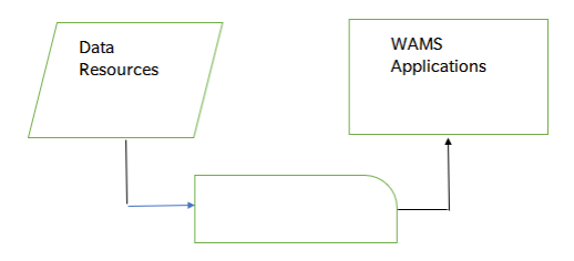
Fig. 1. WAMS Process in Power Systems.
An inspection of the above-mentioned facts together with Fig. 1 indicates that data itself is the fundamental requirement to perform WAMS functions. It can also be concluded that each sub-process has different responsibilities and different tasks that should be performed on system data. Consequently, WAMS main sub-processes should be studied from the data point of view. In the rest of this chapter, data resources, applications and communication infrastructure of WAMS will be investigated.
4. Data resources of WAMS
Online data and information from the entire system have been essential for secure operation and control of interconnected systems e.g. Power systems. In general, system data and information have been provided by data resources of system, which are also called measuring devices (Shahraeini et al., 2010). Data provided by data resources are widely different in terms of their importance, format, volume, sample rate and etc. Thomas et al. (2006) have classified power system data into two main data groups: Operational and Non-Operational data.
5. The operational data includes the instantaneous measurements of voltages, currents, phasors and breaker statuses that are measured by intelligent devices. Such data is transmitted continuously to the control center(s) through communication systems.
6. Occasionally, they may be used locally for the local decision making. On the other hand, the non-operational data basically consists of records or logs of multiple events e.g. Series of faults, power fluctuations, disturbances and lightning strikes. Typically, the non-operational data is offline data. This means that they are transmitted to the control center(s) either in the specified time intervals (e.g. Multiple hours) or when they are requested by the system operator.
7. There are two main differences between the operational and the non-operational data. The first one is their polling rates. The operational data are normally polled in a regular mode i.e. a continuous stream of data. On the other hand, most of the non-operational data are polled at the defined conditions or they are periodically polled at a specified time intervals.
Another major difference is their data format. The operational data is usually transmitted in the form of a stream i.e. stream of numerical variables. While the non-operational data may appear in different formats e.g. Waveforms, numerical values, COMTRADE (Common format for Transient Data Exchange) format etc. (Thomas et al., 2006).
8. In this book, the classification of power system data represented by Thomas et al. (2006), is generalized to the data resources of power systems as well. In this section, these two classes of data resources; i.e. operational and non-operational data resources; are summarized in separate subsections. Supervisory Control and Data Acquisition (SCADA) and Synchronized Phasor Measurement System (SPMS) are two operational data resources that will be studied. Alternatively, Digital Fault Recorder (DFR), Digital Protective Relay (DPR) and Circuit Breaker Monitor (CBM) will be investigated as non-operational data resources.
Reference Books:
- [R1] Badri Ram, D. N. Vishwakarma, “Power System Protection and Switchgear”, Tata McGraw Hill Publishing Co. Ltd.
- [R2] J Lewis Blackburn, “Protective Relaying- Principles and Applications”, Dekker Publications.
- [R3] Prof. Dr S.A. Soman, IIT Mumbai, A Web course on “Digital Protection of power System”
- [R4] A.G. Phadke, J.S. Thorp ,Computer relaying for Power System , Research Studies Press LTD, England.(John Willy and Sons Inc New York)
- [R5] Mason C.R., “Art and Science of Protective Relaying”, Wiley Eastern Limited.
- [R6] Arun Ingole, “Switchgear and Protection”, Pearson.