Unit I
Classification Of Measuring Instruments
I. Classification of Measurement Instruments
The performance characteristics of a measurement system are examined by measuring the desired input. It gives an impression that how thoroughly it rejects the undesirable inputs. The system is broadly defined in terms of Static and Dynamic characteristics.
It involves the measurement of constant or slowly varying quantities. Under those conditions a set of performance criteria are defined that gives a meaningful description of the quality of measurement without interfering with dynamic description that involves the use of differential equations. Some of static characteristics of every instrument are:
(i) Accuracy: Accuracy is the closeness with which an instrument reading approaches the true value of the quantity being measured. The accuracy of an instrument is quantified by the difference of its readings & the one given by the primary standard. The accuracy may be specified in terms of error, a) Point Accuracy, b) Accuracy as % of True Value = [(Measured Value - True Value)*100]/True Value, c) Accuracy as % of full scale deflection = [(Measured Value – True Value)*100]/Maximum Scale Value
(ii) Precision: It is defined as the ability of instrument to reproduce a certain set of readings within given accuracy. It describes an instrument’s degree of random variations in its output when measuring the constant quantity. It depends upon repeatability.
(iii) Repeatability: It is defined as ability of instrument to reproduce a group of measurements of same measured quantity, made by same observer, using same instrument, under same conditions.
(iv) Resolution: It is the minimum change or smallest increment in the measured value that can be detected with certainty by the instrument. It can be least count of instrument.
(v) Dead Space/Threshold: It is defined as the range of different input values over which there is no change in output value. It is due to static friction or hysteresis.
(vi) Tolerance: It is a term closely related to accuracy & defines the maximum error that is to be expected in some value. It describes the maximum deviation of manufactured component from some specified value.
(vii) Range/Span: The range or span of an instrument defines the minimum & maximum values of a quantity that the instrument is designed to measure.
(viii) Linearity: This is the closeness to a straight line of the relationship between the true process variable and the measurement i.e. deviation of transducer output curve from a specified straight line. It is reported as non- linearity, which is the maximum of deviation between the calibration curve & a straight line positioned so that the maximum deviation is minimized.
(ix) Sensitivity of measurement: It is a measure of the change in instrument output that occurs when the quantity being measured changes by a given amount. Thus, sensitivity is the ratio of:
Static Sensitivity, K =  =
= 
(x) Reliability: It is the probability that a device will adequately perform (as specified) for a period of time under specified operating conditions. Some sensors are required for safety or product quality, and therefore, they should be very reliable.
They are concerned with the measurement of quantities that vary with time. It describes its behavior between the time a measured quantity changes value and the time when the instrument output attains a steady value in response. As with static characteristics, any values for dynamic characteristics quoted in instrument data sheets only apply when the instrument is used under specified environmental conditions. Outside these calibration conditions, some variation in the dynamic parameters can be expected. A dynamic system is represented by differential equation. The dynamic behavior of measurement is studied in two domains: Time Domain & Frequency Domain.
Mathematical Model
A measurement system can be represented by ordinary linear differential equation with constant coefficients. The relationship can be represented as


Where, 

a’s & b’s = constants representing the physical parameters of the system
The above representation relates  &
&  in time domain. The solution of this equation can be obtained either by method of D operates or by the Laplace Transform.
Time Domain Analysis
In this, the input signal is applied to the system & the behavior is studied as a function of time. The output is supposed to follow the input as closely as possible & it is important to compare the output & input variables at all times. The dynamic response of the system to different types of inputs which are function of time, is analyzed at different intervals of time after the application of input signal. In practice, the input signals applied to a measurement system are not known, hence the purpose of analysis & design some basic types of input signals like step, ramp, parabolic & impulse input are defined.
Frequency Domain Analysis
The frequency domain analysis pertains to the steady state response of the system to a sinusoidal input. The sinusoid is a unique input signal, and the resulting output signal for a linear system is sinusoidal in the steady state. However the output signal differs the input waveform in amplitude and phase.
It is important to analyze the system behavior in frequency domain through application of sinusoidal input signals because
- The system may be subjected to a periodically varying sinusoidal signal while in actual use.
- If the system is subjected to time varying complex waveform, which can be thought of as composed of sinusoidal signals of different frequencies. Hence the total response may be obtained by superposition of the responses at different frequencies.
- A system is subjected to various types of time varying signals, all these varying signals can be expressed in terms of sinusoidal signals of different amplitude & frequencies. Therefore the total response of the system can be obtained by superposition of responses.
When a signal is subjected to sinusoidal input, 
The output is 
Where  are respectively the amplitude of input & output and
  is the phase difference between input & output.
Calibration is a comparison of measuring equipment against a standard instrument of higher accuracy to detect, correlate, adjust, rectify and document the accuracy of the instrument being compared. Typically, calibration of an instrument is checked at several points throughout the calibration range of the instrument. The calibration range is defined as “the region between the limits within which a quantity is measured, received or transmitted, expressed by stating the lower and upper range values.” The limits are defined by the zero and span values. The zero value is the lower end of the range. Span is defined as the algebraic difference between the upper and lower range values.
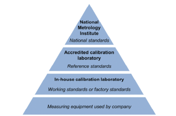
Illustration of Calibration Hierarchy
Calibration Tolerance: Every calibration should be performed to a specified tolerance. The terms tolerance and accuracy are often used incorrectly. In ISA’s The Automation, Systems, and Instrumentation Dictionary, the definitions for each are as follows:
Accuracy: The ratio of the error to the full scale output or the ratio of the error to the output, expressed in percent span or percent reading, respectively.
Tolerance: Permissible deviation from a specified value; may be expressed in measurement units, percent of span, or percent of reading.
As you can see from the definitions, there are subtle differences between the terms. It is recommended that the tolerance, specified in measurement units, is used for the calibration requirements performed at your facility. By specifying an actual value, mistakes caused by calculating percentages of span or reading are eliminated. Also, tolerances should be specified in the units measured for the calibration.
Need for Calibration
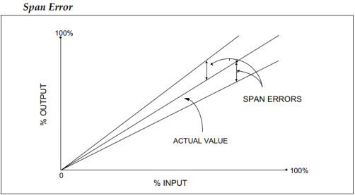
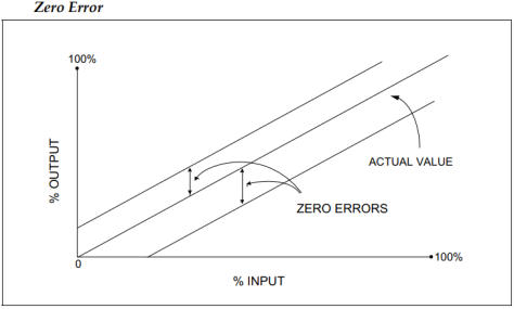
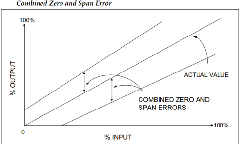
Instrument error can occur due to a variety of factors: drift, environment, electrical supply, addition of components to the output loop, process changes, etc. Since a calibration is performed by comparing or applying a known signal to the instrument under test, errors are detected by performing a calibration. An error is the algebraic difference between the indication and the actual value of the measured variable. Typical errors that occur include:
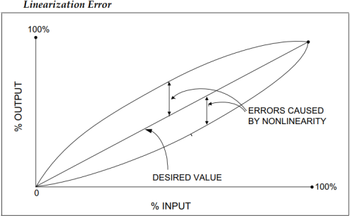
Zero and span errors are corrected by performing a calibration. Most instruments are provided with a means of adjusting the zero and span of the instrument, along with instructions for performing this adjustment. The zero adjustment is used to produce a parallel shift of the input-output curve. The span adjustment is used to change the slope of the input-output curve. Linearization error may be corrected if the instrument has a linearization adjustment. If the magnitude of the nonlinear error is unacceptable and it cannot be adjusted, the instrument must be replaced. To detect and correct instrument error, periodic calibrations are performed. Even if a periodic calibration reveals the instrument is perfect and no adjustment is required, we would not have known that unless we performed the calibration. And even if adjustments are not required for several consecutive calibrations, we will still perform the calibration check at the next scheduled due date. Periodic calibrations to specified tolerances using approved procedures are an important element of any quality system.
An instrument is a device in which we can determine the magnitude or value of the quantity to be measured. The measuring quantity can be voltage, current, power and energy etc.
Generally instruments are classified in to two categories.
Absolute Instruments
An absolute instrument determines the magnitude of the quantity to be measured in terms of the instrument parameter. This instrument is really used, because each time the value of the measuring quantities varies. So we have to calculate the magnitude of the measuring quantity, analytically which is time consuming. These types of instruments are suitable for laboratory use.
Example: Tangent galvanometer, Rayleigh Current Balance & Absolute Electrometer.
Secondary Instruments
This instrument determines the value of the quantity to be measured directly. Generally these instruments are calibrated by comparing with another standard secondary instrument. Examples of such instruments are voltmeter, ammeter and wattmeter etc. Practically secondary instruments are suitable for measurement and are of three types.
- Indicating Instruments
Indicating instruments are those which indicate the magnitude of an electrical quantity at the time when it is being measured. The indications are given by a pointer moving over a graduated dial. Ordinary Ammeters, Voltmeters, Wattmeter, Frequency meters, power factor meters are few examples.
- Recording Instruments
Recording instruments are those which keep a continuous record of the variations of the magnitude of an electrical quantity to be observed over a definite period of time. In such instruments the moving system carries an inked pen which touches lightly a sheet of paper wrapped over a drum moving with uniform slow motion in a direction perpendicular to that of the deflection of the pointer. Thus a curve is traced which shows the variations in the magnitude of the electrical quantity under observation over a definite period of time. Such instruments are generally used in power houses where the current, voltage & power etc are to be maintained with specified values.
- Integrating Instruments
Integrating instruments are those which measure the total amount of either quantity of electricity or electrical energy supplied over a period of time. The summation, given by such an instrument is the product of time & electrical quantity under measurement. The ampere-hour meters & energy meters fall into this class.
- Electrical Measuring Instrument
(i) Deflecting Torque: The deflecting torque is produced by using the following methods of magnetic, heating, chemical, electrostatic & electro-magnetic induction effects of current or voltage and causes the moving system of the instrument to move from its zero position when the device is connected in the electrical circuit to measure the electrical quantity. The method of producing this torque depends upon the type of device.
(ii) Controlling Torque: This torque balances the deflecting torque & hence ensures that the magnitude of the deflection is always same for a particular value of the quantity to be measured. It also brings back the moving system to tits zero position. Without this torque, the pointer would swing over its maximum deflected position and it would not return to its zero position on removing the supply. This torque is created either by spring control or by gravity control.
(a) Spring Control: The phosphor bronze hair spirals A & B coiled in opposite directions & acting one against the other and are attached to spindle as shown in the figure. Under the influence of deflecting torque when the pointer moves, one of the springs extended while the other is compressed. This produces controlling torque which is directly proportional to the angle of deflection of the moving device. When deflecting torque  & controlling torque
  are equal, the pointer comes to rest in its final deflected position. The controlling torque developed in a spiral spring is given by
 , where,
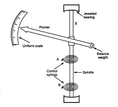
E = Young’s Modulus of spring material in kg/m2
L = Total Length of spring strip in m
b = width of spring in m
t = thickness of spring
Ks = spring constant
The stress developed in the spring must be below the elastic limit of spring material at the maximum deflection of the moving system. The cross-section area of the spring must be sufficient to carry the current without overheating. The spring in most cases, must be of non-magnetic material at equilibrium, Td = Tc.
If the deflecting torque is directly proportional to the current,
Td = K I
Tc = Ks ϴ
Therefore, I = (Ks/K) ϴ
So the current is proportional to deflection & hence the scale will be uniform.
(b) Gravity Control: In this type of control, a small weight is attached to the moving system, in the given figure, such that the deflection torque has to act against the action of gravity, thus controlling torque is obtained.
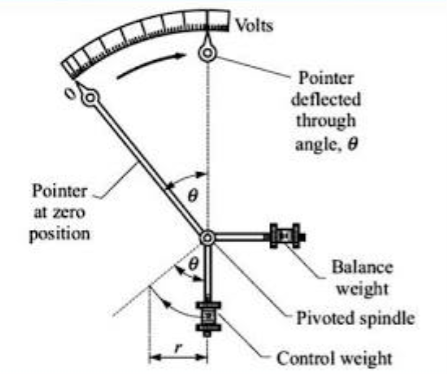
When the control weight is in vertical position, the controlling torque is zero and hence the pointer is at zero position. Let the system deflects through an angle ϴ. The weight acts at a distance l from the centre, the component of weight trying to restore the pointer back to zero position W.sinϴ.
Therefore, controlling torque is,

Where, l is the distance of weight from the axis of rotation &  is gravity constant. If the deflecting torque is directly proportional to the current

At equilibrium,
 or
or

Here the current is directly proportional to sin and hence, the scale is not uniform. It is cramped at lower end.
(iii) Damping Torque
Damping torque is required to avoid oscillations of the moving system about its final deflected position owing to the inertia of the moving parts and to bring the moving system to rest in its final deflected position.
If the system is under-damped, the moving system will oscillate about its final deflected position & take some time to rest in its steady position. If the system is over-damped, the moving system will become slow & when the degree of damping is such that the pointer rises quickly to its final deflected position without oscillations.
The various methods for producing damping torque are:
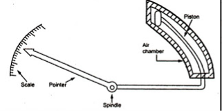
(a) Air Friction Damping: The piston is mechanically connected to a spindle through the connecting rod. The pointer is fixed to the spindle moves over a calibrated dial. When the pointer oscillates in clockwise direction, the piston goes inside and the cylinder gets compressed. The air pushes the piston upwards and the pointer tends to move in anticlockwise direction. If the pointer oscillates in anticlockwise direction the piston moves away and the pressure of the air inside cylinder gets reduced. The external pressure is more than that of the internal pressure. Therefore the piston moves down wards. The pointer tends to move in clock wise direction.
(b) Fluid Friction Damping: This form of damping is similar to air friction but here oil is used in place of air and the viscosity of oil is greater, the damping force will be greater.
A disc attached to the moving system as shown in figure (a), dips into an oil pot & is completely submerged in oil. When the moving system moves, the disc moves in oil & a fractional drag is produced which opposes the motion.
In fig (b), number of vanes is attached to the spindle and these vanes are submerged in oil & move in a vertical plane. This arrangement gives a greater damping torque.
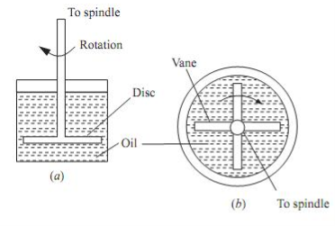
The oil used for this method shouldn’t evaporate quickly, must be a good insulator, shouldn’t have any corrosive action on metals & its viscosity shouldn’t change with temperature.
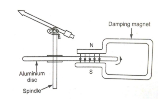
(c) Eddy Current Damping: It is the most effective form of damping. The essential component is the permanent magnet & alight disc of conducting material mostly aluminum or copper. The principal is such that when a conductor moves in a magnetic field an EMF is induced in it & by providing a closed path the eddy currents will flow. This current interacts with the magnetic field to produce an electromagnetic torque which opposes the motion. This torque is proportional to EMF which in turn is proportional to velocity of the conductor. Thus damping torque is proportional to the velocity of the disc.
Ammeters & Voltmeters, except electrostatic voltmeters, operate on the same principle. The ammeters carry the current to be measured or a definite fraction of it & this current or its definite fraction produces the deflecting torque whereas the voltmeter carries the current proportional to the voltage to be measured which produces the deflecting torque.
Ammeter, which is connected in series with the circuit carrying the current under measurement, must be of very low resistance so that the voltage drop across the meter & power absorbed from the circuit as is as low possible.
Voltmeter, which is connected in parallel with the circuit across which the voltage is to be measured, must be of very high resistance so that the current flowing in the circuit & the power is absorbed from the circuit is minimum.
It is impractical for an instrument to be manufactured as voltmeter to be employed as an ammeter, or alternatively. The low resistance winding of an ammeter will suffer damage if connected directly across a high voltage. However, an ammeter of low range may be used as a voltmeter by connecting a high resistance in series provided the current through the series combination is within the range of ammeter when connected across the voltage.
MI instruments are widely used for AC & DC measurement & are cheapest in cost & robust in construction. There are two types of moving iron instrument:
- Attraction Type
- Repulsion Type
(a) Attraction Type:
Construction:
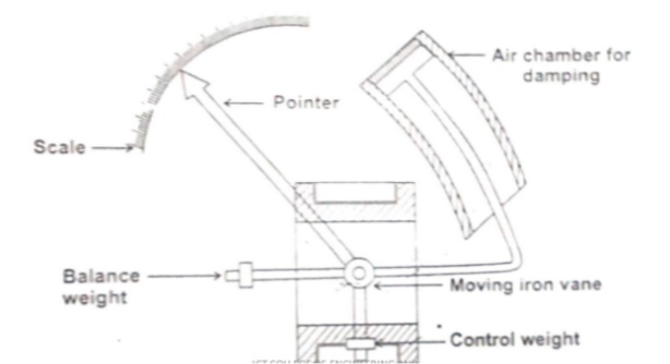
The moving iron fixed to the spindle is kept near the hollow fixed coil. The pointer and balance weight are attached to the spindle, which is supported with jeweled bearing. Here air friction damping is used.
Principle of operation
The current to be measured is passed through the fixed coil. As the current is flow through the fixed coil, a magnetic field is produced. By magnetic induction the moving iron gets magnetized. The north pole of moving coil is attracted by the south pole of fixed coil. Thus the deflecting force is produced due to force of attraction. Since the moving iron is attached with the spindle, the spindle rotates and the pointer moves over the calibrated scale. But the force of attraction depends on the current flowing through the coil.
Torque developed by MI
Let ‘ϴ’ be the deflection corresponding to a current of ‘i’ ampere.
Let the current increases by ‘di’, corresponding deflection is ‘ϴ+dϴ’
There is change in inductance since the position of moving iron change wrt the fixed electromagnets.
Let the new inductance value be ‘L+dL’. The current change by ‘di’ is dt seconds
Let the emf be induced in the coil be ‘e’ volt

Multiplying by  in the above equation


The above equation gives the energy & used in two forms. Part of energy is stored in the inductance. Remaining energy is converted in to mechanical energy which produces deflection.
Change in Energy stored = Final Energy – Initial Energy stored


Mechanical work done to move the pointer by 

By law of conservation of energy
Electrical Energy supplied = Increase in stored energy + mechanical work done


At steady state condition 


When the instruments measure AC,  rms
rms
Scale of the instrument is non uniform
Advantages
- MI can be used in AC & DC
- Supply is given to a fixed coil & not moving coil
- Simple construction & less friction error
Disadvantages
- It suffers from eddy current & hysteresis error.
- Scale is not uniform & consumes more power
- Calibration is different for AC & DC operation
(b) Repulsion Type:
Construction:
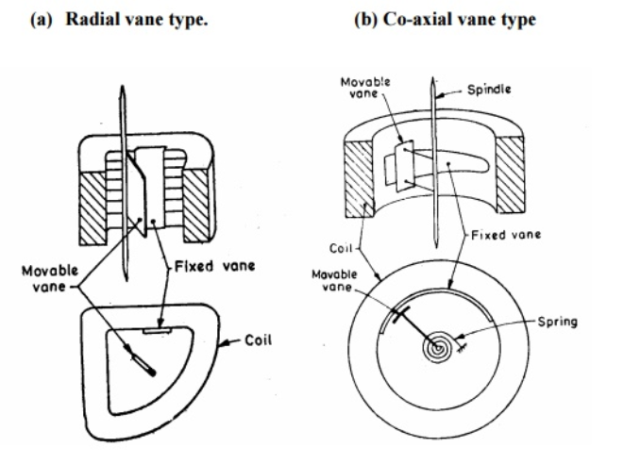
In this type, there are two vanes inside the coil one fixed & other movable. These two vanes are similarly magnetized when the current flows through the coil & there is a force of repulsion between the two vanes resulting in the movement of the moving vane.
(I)Radial Vane Type: The vanes are radial strips of iron. The strips are placed within the coil as shown in fig (a). The fixed vane is attached to the coil & the movable one to the spindle of the instrument.
(II)Co-Axial Vane Type: The fixed & moving vanes are sections of coaxial cylinders as shown in fig (b)
Principle of operation: When the current flows through the coil, a magnetic field is produced by it. So both fixed iron and moving iron are magnetized with the same polarity, since they are kept in the same magnetic field. Similar poles of fixed and moving iron get repelled. Thus the deflecting torque is produced due to magnetic repulsion. Since moving iron is attached to spindle, the spindle will move. So that pointer moves over the calibrated scale. Damping: Air friction damping is used to reduce the oscillation. Control: Spring control is used.
B. Range Extension
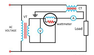
A transformer that is used to measure electrical quantities like current, voltage, power, frequency and power factor is known as an instrument transformer. These transformers are mainly used with relays to protect the power system. The purpose is to step down the voltage & current of the AC system because the level of voltage & current in a power system is extremely high. In general, these instruments are mainly designed for 5 A & 110 V.
Instrument Transformer is of two types: Current & Potential Transformer
The CT is used with their primary winding connected in series with the line carrying current to be measured. The primary current depends upon the load but is independent of load connected on secondary winding of the CT. The primary consists of few numbers of turn & secondary has large number of turns. The ammeter or the current coil of the wattmeter is connected directly across the secondary terminals.
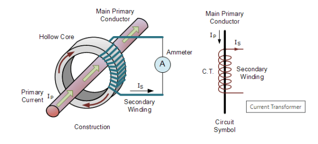
Core
The core has low reluctance & low core losses, in order to minimize the errors due to magnetizing current & core loss component. The reduction of reluctance path can be brought about by using materials of high permeability, short magnetic path, large cross section area & a low value of flux density. Magnetic materials used to design the core are Hot Rolled Silicon Steel, Cold Rolled Grain Oriented and Nickel Iron Alloys.
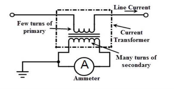
Windings
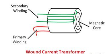
(i) Wound Transformer: In this transformer the primary winding is composed inside the transformer. The primary winding had a single turn and connected in series with the conductor that measured the current. The wound transformer is mainly used for measuring the current from 1amps to 100 amps.
(ii) Bar Type Current Transformer: The bar type transformer has only secondary windings. The conductor on which the transformer is mounted will act as primary windings of the current transformers.
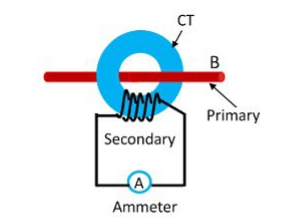
(iii) Toroidal Current Transformer: This transformer does not contain primary windings. The line through which the current flow in the network is attached through a hole or a window of the transformers. The major advantage of this transformer is that the transformer has a symmetrical shape due to which it has a low leakage flux, thus less electromagnetic interference.
Advantages of Current Transformer
- The larger current values can be easily measured.
- Its capability to isolate the high voltage and current to low values ensure safe operations and handling
the equipment in a safe manner. - It can be used as a controlling device to operate protecting devices such as relays and pilot lights.
- Numerous instruments can be feeding on a single transformer.
The potential transformer may be defined as an instrument transformer used for the transformation of voltage from a higher value to the lower value. This transformer step down the voltage to a safe limit value which can be easily measured by the ordinary low voltage instrument like a voltmeter, wattmeter and watt-hour meters, etc.
Construction
The potential transformer is made with high-quality core operating at low flux density so that the magnetizing current is small. The terminal of the transformer should be designed so that the variation of the voltage ratio with load is minimum and the phase shift between the input and output voltage is also minimum.
The primary winding has a large number of turns, and the secondary winding has a much small number of turns. For reducing the leakage reactance, the co-axial winding is used in the potential transformer. The insulation cost is also reduced by dividing the primary winding into the sections which reduced the insulation between the layers.
Types of PT
The potential transformer is mainly classified into two types, i.e., the conventional wound types (electromagnetic types) and the capacitor voltage potential transformers.
Conventional wound type transformer is very expensive because of the requirement of the insulations; capacitor potential transformer is a combination of capacitor potential divider and a magnetic potential transformer of relatively small ratio.
The circuit diagram of the capacitor potential transformer is shown in the figure below. The stack of high voltage capacitor from the potential divider, the capacitors of two sections becomes C1 and C2, and the Z is the burden.
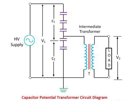
The voltage applied to the primary of the intermediate transformer is usually of the order 10kV. Both the potential divider and the intermediate transformer have the ratio and insulation requirement which are suitable for economical construction.
The intermediate transformer must be of very small ratio error, and phase angle gives the satisfactory performance of the complete unit. The secondary terminal voltage is given by the formula shown below.

Voltage Ratio & Phase Angle Errors of PT
The primary and the secondary voltage is exactly proportional to the primary voltage and exactly in phase opposition. But this cannot be achieved practically due to the primary and secondary voltage drops. Thus, both the primary and secondary voltage is introduced in the system.
Voltage Ratio Error: The voltage ratio error is expressed in regarding measured voltage, and it is given by the
formula as shown below.

Where, Kt = is the nominal ratio, i.e., the ratio of the rated primary voltage and the rated secondary voltage. Is= Secondary Current
Ip= Primary Current
Phase Angle Error: The phase angle error is the error between the secondary terminal voltages which is exactly in phase opposition with the primary terminal voltage. The increases in the number of instruments in the relay connected to the secondary of the potential transformer will increase the errors in the potential transformers.
Applications of PT
- It is used for a metering purpose.
- For the protection of the feeders.
- For protecting the impedance of the generators.
- For synchronizing the generators and feeders.
Transformation Ratio
 For Current Transformer
 For Potential Transformer
Nominal Ratio
 For Current Transformer
 For Potential Transformer
Turns Ratio
 For Current Transformer
 For Potential Transformer
Where,
IP = Primary Current
Is = Secondary Current
Vs = Secondary Voltage
VP = Primary Voltage
NS = Secondary Turns
NP = Primary Turns
Ratio Correction Factor (RCF)


The ratio marked on the transformer is their nominal ratio
References
1) R.K. Rajput -“Electrical Measurements and Measuring Instruments” – S. Chand Limited, 2009
2) J.B. Gupta - “ Electrical Measurements and Measuring Instruments ” – S.K. Kataria & Sons
3) E.W. Golding - “ Electrical Measurements and Measuring Instruments ”