Unit II
Measurement Of Resistance
I. Measurement of Resistance
Resistors are used in electrical circuits to perform a variety of tasks. Properties of resistances play an important role in determining performance specifications for various circuit elements including coils, windings, insulations, etc. It is important in many cases to have reasonably accurate information of the magnitude of resistance present in the circuit for analyzing its behavior. Measurement of resistance is thus one of the very basic requirements in many working circuits, machines, transformers, and meters. Resistors are used as standards for the measurement of other unknown resistances and for the determination of unknown inductance and capacitance. For measurement of resistance we have divided this section in three parts as shown in the given figure:

The major problem in measurement of low resistance values is the contact resistance or lead resistance of the measuring instruments, though being small in value is comparable to the resistance being measured and hence causes serious error.
Thus to eliminate this issue small valued resistance are constructed with four terminals. Two terminals are current terminals and other two are potential terminals.
Figure below shows the construction of low resistance.
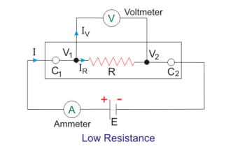
The current is flown through current terminals C1 and C2 while the potential drop is measured across potential terminals V1 and V2. Hence we can find out the value of resistance under experiment in terms of V and I as indicated in the above figure. This method helps us to exclude the contact resistance due to current terminals and though contact resistance of potential terminals still comes into picture, it is very small fraction of high resistance potential circuit and hence induces negligible error.
Kelvin’s double bridge is a modification of simple Wheatstone bridge. Figure below shows the circuit diagram of Kelvin’s double bridge.
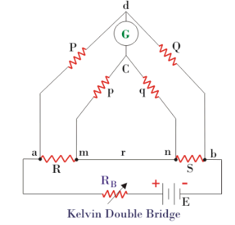
As we can see in the above figure there are two sets of arms, one with resistances P and Q and other with resistances p and q. R is the unknown low resistance and S is a standard resistance. Here r represents the contact resistance between the unknown resistance and the standard resistance, whose effect we need to eliminate. For measurement we make the ratio P/Q equal to p/q and hence a balanced Wheatstone bridge is formed leading to null deflection in the galvanometer. Hence for a balanced bridge we can write:
Ead = Eamc

Where, 
Using the value of Eab in the above equation & solving it using P/Q=p/q, we get

Hence we see that by using balanced double arms we can eliminate the contact resistance completely and hence error due to it. To eliminate another error caused due to thermo-electric emf, we take another reading with battery connection reversed and finally take average of the two readings. This bridge is useful for resistances in range of 0.1µΩ to 1.0 Ω.
Following methods are used for measuring the resistance ranging between 1Ω to 100 kΩ. Most of the electrical apparatus used in practice, electronic circuits, carbon resistance and metal film resistors are found to have resistance values lying in this range.
Ammeter Voltmeter Method
It is the simplest method of measuring resistance using one ammeter & voltmeter to measure the current & voltage respectively and we get the value of resistance as

There are two possible connections of ammeter and voltmeter, shown in the figure below.
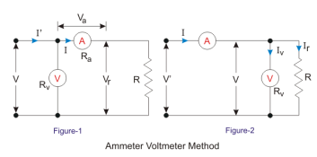
In fig 1, the voltmeter measures voltage drop across ammeter and the unknown resistance, hence


Therefore, the relative error will be


For connection in figure 2, the ammeter measures the sum of current through voltmeter and resistance, hence


The relative error will be

It can be observed that the relative error is zero for Ra = 0 in first case and Rv = ∞ in second case. Now the questions stand that which connection to be used in which case. To find out this we equate both the errors;

Hence for resistances greater than that given by above equation we use the first method and for less than that we use second method.
This is the simplest and the most basic bridge circuit used in measurement studies. It mainly consists of four arms of resistance P, Q; R and S. R is the unknown resistance under experiment, while S is a standard resistance. P and Q are known as the ratio arms. An EMF source is connected between points a and b while a galvanometer is connected between points c and d.
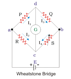
A bridge circuit always works on the principle of null detection, i.e. we vary a parameter until the detector shows zero and then use a mathematical relation to determine the unknown in terms of varying parameter and other constants. Here also the standard resistance, S is varied in order to obtain null deflection in the galvanometer. This null deflection implies no current from point c to d, which implies that potential of point c and d is same. Hence,

Also,  and
and 
Combining the above two equation, we get

Resistances higher than 100 kΩ are classified as high resistances. Insulation resistances in electrical equipment are expected to have resistances above this range.
Following method is used to measure high resistance in electrical circuit;
One of the most popular portable type insulation resistance measuring instruments is the megohmmeter or in short, megger. The megger is used very commonly for measurement of insulation resistance of electrical machines, insulators, bushings, etc. The traditional analog deflecting-type megger is essentially a permanent magnet crossed-coil shunt type ohmmeter.
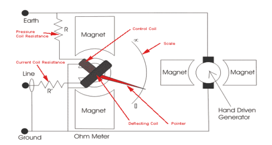
Deflecting and Control coil: Connected parallel to the generator, mounted at right angle to each other and maintain polarities in such a way to produced torque in opposite direction.
Permanent Magnets: Produce magnetic field to deflect pointer with North-South pole magnet.
Pointer: One end of the pointer connected with coil another end deflects on scale from infinity to zero.
Scale: A scale is provided in front-top of the megger from range ‘zero’ to ‘infinity’; enable us to read the value.
D.C generator or Battery connection: Testing voltage is produced by hand operated DC generator for manual operated Megger. Battery / electronic voltage charger is provided for automatic type Megger for same purpose. Pressure Coil Resistance and Current Coil Resistance: Protect instrument from any damage because of low external electrical resistance under test.
Voltage for testing produced by hand operated megger by rotation of crank in case of hand operated type; a battery is used for electronic tester.
500 Volt DC is sufficient for performing test on equipment range up to 440 Volts. 1000 V to 5000 V is used for testing for high voltage electrical systems.
Deflecting coil or current coil connected in series and allows flowing the electric current taken by the circuit being tested. The control coil also known as pressure coil is connected across the circuit. Current limiting resistor (CCR and PCR) connected in series with control and deflecting coil to protect damage in case of very low resistance in external circuit. In hand operated megger electromagnetic induction effect is used to produce the test voltage i.e. armature arranges to move in permanent magnetic field or vice versa.
Where as in electronic type megger battery are used to produce the testing voltage. As the voltage increases in external circuit the deflection of pointer increases and deflection of pointer decreases with a increases of current.
Hence, resultant torque is directly proportional to voltage and inversely proportional to current. When electrical circuit being tested is open, torque due to voltage coil will be maximum and pointer shows ‘infinity’ means no shorting throughout the circuit and has maximum resistance within the circuit under test. If there is short circuit pointer shows ‘zero’, which means ‘NO’ resistance within circuit being tested.
Work philosophy based on ohm-meter or ratio-meter. The deflection torque is produced with megger tester due to the magnetic field produced by voltage and current, similarly like ‘Ohm’s Law’.
The torque of the megger varies in a ration with V/I, (Ohm’s Law: - V = IR or R = V/I). Electrical resistance to be measured is connected across the generator and in series with deflecting coil.
Produced torque shall be in opposite direction if current supplied to the coil.
- High Resistance = No Current: - No current shall flow through deflecting coil, if resistance is very high i.e. infinity position of pointer.
- Small Resistance = High Current :- If circuit measures small resistance allows a high electric current to pass through deflecting coil, i.e. produced torque make the pointer to set at ‘ZERO’.
- Intermediate Resistance = Varied Current: - If measured resistance is intermediate, produced torque align or set the pointer between the range of ‘ZERO to INIFINITY’.
The measurement of earth resistance is made by the potential fall method. The resistance area of the earth electrode is the area of the soil around which a voltage gradient is measured with a commercial instrument. In the figure shown below E is the earth electrode under rest, and A is an auxiliary earth electrode positioned so that two resistance areas do not overlap. B is the second auxiliary electrode which is placed between E and A.
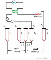
An alternating current of steady state value passes through the earth path from E to A and the voltage drop between E and B is measured.


The electrode B is moved from position B1 and B2 respectively so that the resistance area does not overlap. If the resistance values determined is of approximately the same in all three cases, the mean of the three readings can be taken as the earth resistance of the earth electrode.
The auxiliary earth electrode A must be driven in at a point further away from E and the above test repeated until the group of three readings obtained are in good agreement. The alternating current source is used to eliminate the electrolytic effect.
The test can be performed, with current at power frequency from a double wound transformer, using a voltmeter and an ammeter as shown in the figure above by mean of an earth tester.
The earth tester is a special type of Megger, which sends AC through earth and DC through the measuring instrument. It has got four terminals. Two terminals are shorted to form a common point which is connected to the earth electrode under test. The other two terminals are connected to the auxiliary electrode A and B respectively. The value of the earth resistance is indicated by the instrument directly when its handle is turned at a uniform speed.
II. Measurement of Inductance
Inductance is an electrical parameter that characterizes electric circuit elements (two- or four-terminal networks) that become magnetic field sources when current flows through them. They are called inductors, although inductance is not a unique property of them. Electric current i (A) and magnetic flux Φ (Wb) are interdependent; that is, they are coupled. Inductance is a measurable parameter; therefore, it has a physical dimension, a measurement unit (the henry), as well as reference standards. Inductance is a property of all electrical conductors. It is found as self-inductance L of a single conductor and as mutual inductance M in the case of two or more conductors. Inductors can vary in construction, but windings in the form of coils are the most frequent. Inductors made as windings on ferromagnetic cores have numerous other applications.
AC Bridges are an extension of DC Bridges in its basic form consists of four bridge arms, a source of excitation and a null or balanced detector. These are advantageous in measuring Inductance (L), Capacitance (C), Frequency (F), Mutual Inductance (M), Storage Factor, and Loss Factor.
Sources in AC Bridges
- For low frequency measurement the power line supply act as source of excitation.
- For high frequency measurement the electronic oscillator is used as excitation voltage.
Detectors in AC Bridges
- Headphones: It is used at frequency from 250 Hz to 3-4 kHz and is the most sensitive detector for this range.
- Vibration Galvanometer: It can be used from 5-1000 Hz and are useful in low AF and power.
- Tuneable Amplifier Detector: It can be used at 10 Hz to 100 kHz
- Cathode Ray Oscilloscope: It is used for higher frequency mainly above 5kHz.
This bridge measures the unknown value of inductance by comparison with a variable standard self inductance.
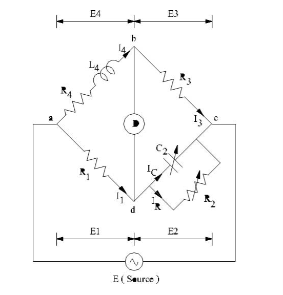
Let R1 & L1 are unknown quantity
L2 = Variable Inductance of fixed resistance ‘r2’
R2 = Variable Resistance connected in series with ‘L2’
R3 & R4 = Known Non-Inductive Resistances
At balance condition,


Equating real & imaginary part we get,


This bridge measures an unknown inductance in terms of a known capacitance.
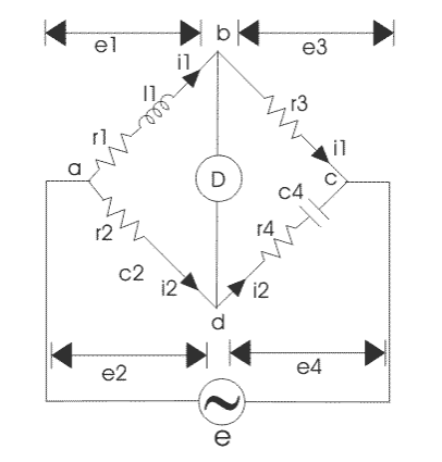
Let R1 & L1 are unknown quantity
R2, R3 & R4 are known-inductive resistances
C4 = variable standard capacitor
At balance condition,

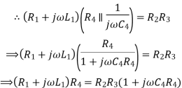
Equating the real & imaginary parts, we get

It is a modification of the Maxwell’s Inductance Capacitance Bridge. In this method, self inductance is measured in terms of standard capacitor.
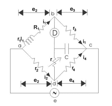
At balance condition, Vb=Ve
So, ID=0
Also for delta network we convert this in star form


So,
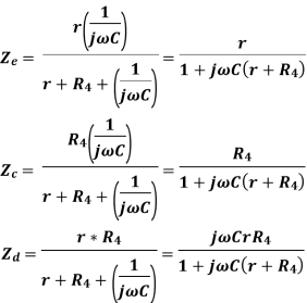
For balance condition,

 [(
[( ]*
]* =
=

Equating Real & Imaginary Part, we get


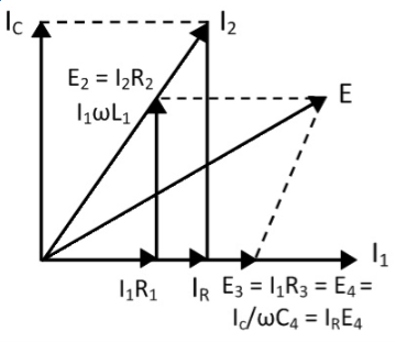
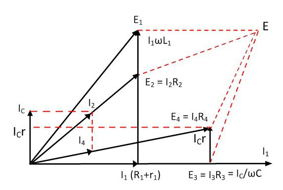
Phasor Diagram
References
1) R.K. Rajput -“Electrical Measurements and Measuring Instruments” – S. Chand Limited, 2009
2) J.B. Gupta - “ Electrical Measurements and Measuring Instruments ” – S.K. Kataria & Sons
3) E.W. Golding - “ Electrical Measurements and Measuring Instruments ”