Unit III
Measurement of Power
Dynamometer type wattmeter works on a very simple principle which is stated as "when any current carrying conductor is placed inside a magnetic field, it experiences a mechanical force and due to this mechanical force, deflection of conductor takes place."
Construction
Dynamometer consists of following parts:
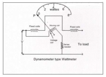
Moving Coil - Moving coil moves the pointer with the help of spring control instrument. A limited amount of current flows through the moving coil so as to avoid heating. So in order to limit the current we have connected the high value resistor in series with the moving coil. The moving is air cored and is mounted on a pivoted spindle and can moves freely. In electrodynamometer type wattmeter, moving coil works as pressure coil. Hence moving coil is connected across the voltage and thus the current flowing through this coil is always proportional to the voltage.
Fixed coil - The fixed coil is divided into two equal parts and these are connected in series with the load, therefore the load current will flow through these coils. Now the reason is very obvious of using two fixed coils instead of one, so that it can be constructed to carry considerable amount of electric current. These coils are called the current coils of electrodynamometer type wattmeter. Earlier these fixed coils are designed to carry the current of about 100 amperes but now the modern wattmeter are designed to carry current of about 20 amperes in order to save power.
Control system - Out of two controlling systems i.e. gravity control and spring control, only spring-controlled systems are used in these types of wattmeter. Gravity controlled system cannot be employed because they will contain appreciable amount of errors.
Damping system - Air friction damping is used, as eddy current damping will distort the weak operating magnetic field and thus it may lead to error.
Scale - There is uniform scale is used in these types of instrument as moving coil moves linearly over a range of 40 degrees to 50 degrees on either side.
Working of Dynamometer
When power is to be measured in a circuit, the instrument is suitably connected in the circuit. The current coil is connected in series with load so that it carries the circuit current. The potential coil is connected across the load so that it carries current proportional to the voltage. Due to the current in the coils, mechanical force exists between them. The result is that the moving coil, moves the pointer over the scale. The pointer comes to rest at a position where deflecting torque is equal to the controlling torque. Reversing the current, reverses the field due to fixed coil as well as the current in the moving coil so that the direction of the deflection torque remains unchanged. Therefore, such instruments can be used for the measurement of a.c as well as d.c power.
Deflecting Torque
It will be proved that deflecting torque is proportional to power in a circuit.
Let us assume that the fixed & moving coils having self-inductances Lf & Lm respectively. Further it is assumed that mutual inductance between fixed & moving coil is M.
Total energy stored in the magnetic field of the coil is given by;

Where if & im are the current through the fixed and magnetic coils, from the above equation it can be derived that torque developed is;

The dynamometer is used to measure the alternating current or voltage, the moving coil- due to its inertia takes a position where the average deflecting torque is balanced by restoring torque for an entire cycle. The deflecting torque is proportional to mean value of square of current or voltage and the instrument scale can be calibrated to read RMS values.
Let the applied voltage be,

Currents through moving & fixed coil are given by;


Where,  is the power factor angle of load (± is leading/lagging)
Instantaneous Deflecting Torque,

The mean/average torque

Where V & I are the RMS values of load voltage & current respectively. The developed torque must be equal to controlling torque at steady state. The controlling torque  and this implies
  Thus an electro-dynamic instrument becomes a wattmeter which will give a direct deflection of the power in either DC/AC circuit.
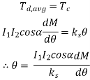
In case ammeter or voltmeter, both the coils are connected ins eries or parallel & the same current is flowing through the coils and therefore the above equation can be written as;

Where I1=I2=I and 
Advantages:
1. These instruments are free from hysteresis losses and eddy current losses.
2. They have a precision grade accuracy.
3. These instruments can be used on both A.C and D.C. They are also used as a transfer instrument.
4. Electrodynamometer voltmeters are very useful where accurate RMS values of voltage, irrespective of waveforms, are required.
Disadvantages
1. They have a non-uniform scale.
2. These instruments have a low sensitivity due to a low torque to weight ratio.
3. They are more expensive than either the PMMC or the M.I type instruments.
4. These instruments are sensitive to overloads and mechanical impacts. Therefore, they must be handled with great care.
5. The operating current of these instruments is large due to the fact that they have a weak magnetic field.
Errors in Electrodynamometer type Wattmeter
The errors in the wattmeter are as follows:
(i) Pressure Coil Inductance: In an ideal dynamo-meter type watt meter the current in pressure coil in phase with the applied voltage. But in practically the pressure coil of watt meter has an inductance and current in it will lag behind the applied voltage. If there is no inductance the current in pressure coil will be in phase with the applied voltage. In the absence of inductance in pressure coil of wattmeter, it will read correctly in all power factors and frequency. The wattmeter will read high when the load power factor is lagging, as in that case the effect of pressure coil inductance is to reduce the phase angle between load current and pressure coil current. Hence the wattmeter will read high. This is very serious error. The wattmeter will read low when the load power factor is leading as in that case the effect of pressure coil inductance is to increase the phase angle between load current and pressure coil current. Hence the wattmeter will read low. Compensation for inductance of pressure coil. Inductance of pressure coil can be reduced by means of capacitor connected in parallel with a portion of multiplier (series resistance).
(ii) Pressure Coil Capacitance: The pressure coil circuit may have capacitance in addition with inductance. This capacitance mainly due to the inter turn capacitance of the series resistance. The effect of capacitance is opposite to that due to inductance. Therefore, the wattmeter will read high when the load power factor is leading. The inductance in pressure coil circuit will always more than inductance, hence the error caused by capacitance will be nullified by that due to inductance.
(iii) Error due to Mutual Inductance: Errors may occur due to the mutual inductance between the current and pressure coils of the watt meter. These errors are quite low at power frequencies. But they increased with increase in frequencies. The effect of mutual inductance can be avoided by arranging the coil system in such a way that they have no mutual inductance. So we can eliminate the errors due to mutual inductance. The Drysdale Torsion head wattmeter is an example.
(iv) Eddy Current Errors: Eddy currents are induced in the solid metal parts and within the thick conductors by the alternating magnetic field produced by the current coil. This eddy currents produce their own magnetic field and it will alter that produced by the main current in the current coil and thus error occurred. This error can be minimized by avoiding solid metal parts as much as possible and by using 32 stranded conductors for high current applications.
(v) Stray Magnetic Field Errors: The electrodynamometer type wattmeter has a weak operating field and therefore it is affected by stray magnetic fields it will result in serious errors. Hence these instruments should be shielded against stray magnetic field.
(vi) Errors caused by vibration of moving system: The torque on the moving system varies with frequency which is twice that of voltage. If the parts of the moving system have a natural frequency which is resonance with the frequency of torque pulsation, the moving system would vibrate with considerable amplitude. These vibrations will cause errors. This error can be reduced by design.
(vii) Temperature Error: The change in room temperature may affect the indication of wattmeter. This is because of change in temperature will change in resistance of pressure coil and stiffness of springs which provide controlling torque. This effect are opposite in nature and cancel each other. The use of material of having negligible temperature coefficient of resistance will reduce change in resistance the pressure coils with change in temperature.
If an ordinary electrodynamometer wattmeter is used for measurement of power in low power factor circuits, (PF<0.5), then the measurements would be difficult and inaccurate since:
- The deflecting torque exerted on the moving system will be very small and
- Errors are introduced due to pressure coil inductance (which is large at LPF)
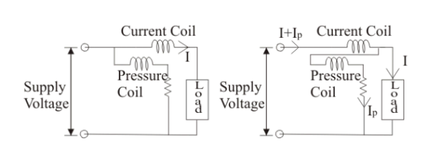
Thus, in a LPF wattmeter, special features are incorporated in a general electrodynamometer wattmeter circuit to make it suitable for use in LPF circuits as under:
(a) Pressure coil current: The pressure coil circuit is designed to have a low value of resistance so that the current through the pressure coil is increased to provide an increased operating torque.
(b) Compensation for pressure coil current: On account of low power factor, the power is small and the current is high.
(c) Compensation for pressure coil inductance: At low power factor, the error caused by the pressure coil inductance is very large. Hence, this has to be compensated, by connecting a capacitor C across a portion of the series resistance in the pressure coil circuit.
(d) Realizing a small control torque: Low power factor wattmeter are designed to have a very small control torque so that they can provide full scale deflection for power factor values as low as 10%.
There are three methods to measure three phase power in three phase circuit on the basis of number of wattmeter used.
3.3.1 Three Watt Meter Method
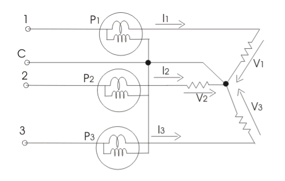
Here, it is applied to three phase four wire systems, current coil of all the three wattmeter marked as 1, 2 and 3 are connected to respective phases marked as 1, 2 and 3. Pressure coils of all the three wattmeter are connected to a common point at neutral line. Clearly each wattmeter will give reading as product of phase current and line voltage which is phase power. The resultant sum of all the readings of wattmeter will give the total power of the circuit. Mathematically we can write

3.3.2 Two Wattmeter Method
There are two types of connection in this method
When the load is star connected, the diagram is as follows
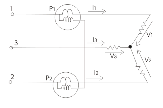
For star connected load clearly the reading of wattmeter one is product of phase current and voltage difference (V2-V3). Similarly the reading of wattmeter two is the product of phase current and the voltage difference (V2-V3). Thus the total power of the circuit is sum of the reading of both the wattmeter. Mathematically we can write;

But we have , hence putting the value of
So,
Total Power = 
When the load is delta connected, the diagram is as follows
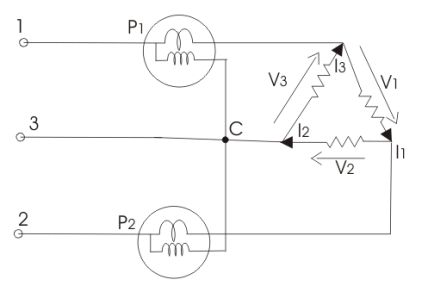
The reading of first wattmeter can be written as;

The reading of second wattmeter can be written as;


But 
Hence total power,

3.3.3 One Wattmeter Method
This method cannot be applied on unbalanced load. So under this condition we have;
 And
And 
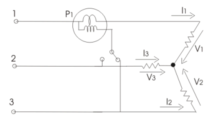
Two switches are given which are marked as 1-3 and 1-2, by closing the switch 1-3 we get reading of wattmeter as;

Similarly when switch 1-2 is closed then the reading of wattmeter is

Hence Total Power P will be;

References
1) R.K. Rajput -“Electrical Measurements and Measuring Instruments” – S. Chand Limited, 2009
2) J.B. Gupta - “ Electrical Measurements and Measuring Instruments ” – S.K. Kataria & Sons
3) E.W. Golding - “ Electrical Measurements and Measuring Instruments ”