Unit-VI
Level Measurement
Point level measurement sensors are used to mark a single discrete liquid height–a preset level condition. They measure fluid level within a range, rather than at a one point, producing an analog output that directly correlates to the level in the vessel.
Two types of methods are used to measure Level they are; Direct/Mechanical Method and Indirect/ Inferential Method
Direct level measurement is simple, almost straightforward and economical; it uses a direct measurement of the distance (usually height) from the datum line, and used primarily for local indication. It is not easily adopted to signal transmission techniques for remote indication or control.
(a) Dip Sticks and Lead Lines
Flexible lines fitted with end weights called chains or lead lines have been used for centuries by seafaring men to gauge the depth of water under their ships. Steel tape having plump bob – like weights, and stored conveniently in a reel are still used extensively for measuring level in fuel oil bunkers and petroleum storage tanks. Though crude as these methods seems, it is accurate to about 0.1% with ranges up to about 20 feet.
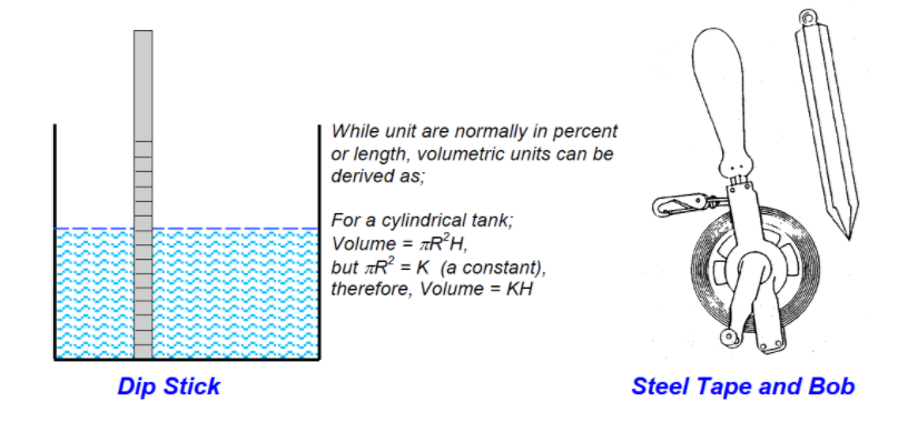
Although the dipstick and lead line method of level measurement are unrivalled in accuracy, reliability, and dependability, there are drawbacks to this technique.
First, it requires an action to be performed, thus causing the operator to interrupt his duty to carry out this measurement. There cannot be a continuous representation of the process measurement.
Another limitation to this measuring principle is the inability to successfully and conveniently measure level values in pressurized vessels. These disadvantages limit the effectiveness of these means of visual level measurement.
(b) Sight Glass
Another simple method is called sight glass (or level glass). It is quite straightforward in use; the level in the glass seeks the same position as the level in the tanks. It provides a continuous visual indication of liquid level in a process vessel or a small tank and is more convenient than dip stick, dip rod and manual gauging tapes.
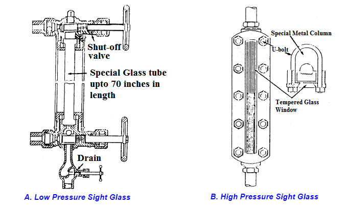
Sight glass A is more suitable for gauging an open tank. A metal ball normal used in the tube to prevent the fluid from flowing out of the gauge. Tubular glass of this sort is available in lengths up to 70 inches and for pressure up to 600 psi. It is now seldom used.
The closed tank sight glass B, sometimes called a ‘reflex glass’, is used in many pressurized and atmospheric processes. The greatest use is in pressurized vessel such as boiler drums, evaporators, condensers, stills, tanks, distillation columns, and other such applications. The length of reflex glass gauges ranges from a few inches or eight feet, but like the tube type gauges, they can be gauge together to provide nearly any length of level measurement.
The simplicity and reliability of gauge type level measurement results in the use of such devices for local indication. When level transmitters fail or must be out of service for maintenance, or during times of power failure, this method allow the process be measured and controlled by manual means. However, glass elements can get dirty and are susceptible to breakage thus presenting a safety hazard especially when hot, corrosive or flammable liquids are being handled.
(c) Chain or Float Gauge
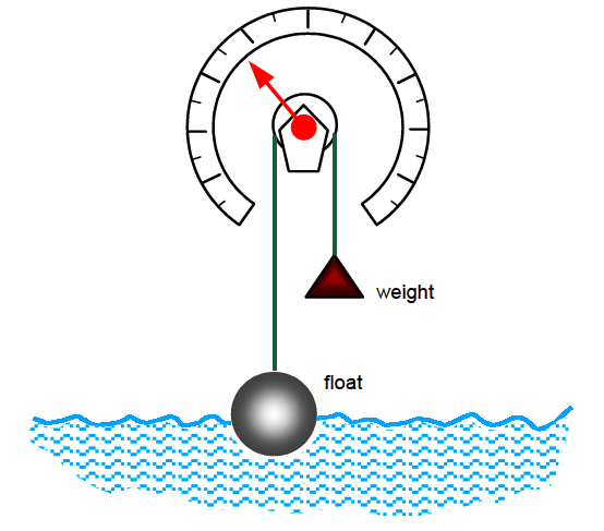
The visual means of level measurement previously discussed are rivaled in simplicity and dependability by float type measurement devices. Many forms of float type instruments are available, but each uses the principle of a buoyant element that floats on the surface of the liquid and changes position as the liquid level varies.
Many methods have been used to give an indication of level from a float position with the most common being a float and cable arrangement. The operational concept of a float and cable is shown in the following diagram;
Indirect or inferred methods of level measurement depend on the material having a physical property which can be measured and related to level. Many physical and electrical properties have been used for this purpose and are well suited to producing proportional output signals for remote transmission. This method employs even the very latest technology in its measurement.
Included in these methods are;
(a) Buoyancy
The force produced by a submerged body which is equal to the weight of the fluid it displaces.
(b) Hydrostatic Head
The force or weight produced by the height of the liquid.
(c) Sonar or Ultrasonic
Materials to be measured reflect or affect in a detectable manner high frequency sound signals generated at appropriate locations near the measured material.
(d) Microwave
Similar to ultrasonic but uses microwave instead of ultrasonic beam
(e) Conductance
At desired points of level detection, the material to be measured conducts (or ceases to conduct) electricity between two fixed probe locations or between a probe and vessel wall.
(f) Capacitance
The material to be measured serves as a variable dielectric between two fixed capacitor plates. In reality, there are two substances which form the dielectric -the material whose measurement is desired and the vapor space above it. The total dielectric value change as the amount of one material increases while the other decreases.
(g) Radiation
The material measured absorbs radiated energy. As in the capacitance method, vapor space above the measured material also has absorbing characteristics, but the difference in absorption between the two is great enough that the measurement can be related quite accurately to measured material.
(h) Weight
The force due to weight can be related very closely to level when its density is constant. Variable concentrations components or temperature variations present difficulties
(i) Resistance
Pressure of the measured material squeezes two narrowly separated conductor together, reducing overall circuit resistance in an amount proportional to level.
(j) Micro Impulse
“time-of-flight”, electrical pulses launch and travels back in frequency directly proportional to the level of the liquid.
II. Displacement Measurement
LVDT is an inductive type passive transducer. It measures force in terms of displacement of ferromagnetic core of a transformer. It converts translational or linear displacement into electrical voltage. It is also known as Linear Variable Differential Transducer.
Principle
It is based on the principle of Electro Magnetic Induction.
Construction
LVDT consists of cylindrical transformer where it is surrounded by one primary winding in the centre of the former and two secondary windings at the sides. The number of turns in both the secondary windings is equal, but they are opposite to each other. The primary winding is connected to the ac source. A movable soft iron core slides within hollow former and therefore affects magnetic coupling between primary and two secondary.
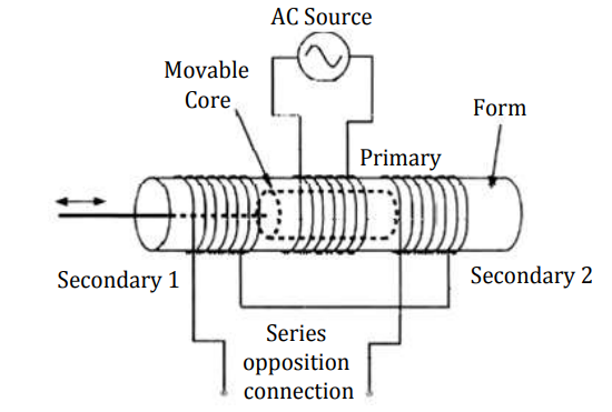
LVDT consist of cylindrical transformer where it is surrounded by one primary winding in the centre of the former and two secondary windings at the sides. The number of turns in both the secondary windings is equal, but they are opposite to each other. The primary winding is connected to the ac source. A movable soft iron core slides within hollow former and therefore affects magnetic coupling between primary and two secondary.
Operation
When the iron core lies at the centre of both secondary, the output differential voltage remains unaffected and have zero magnitude. When the core moves towards secondary-1, it induces more emf across it and less emf across secondary-2. Let’s assume that it is positive displacement. Due to more flux links with the secondary-1 than secondary-2. When the core moves towards secondary-2, it induces more emf across it and less emf across secondary-1. Lt’s assume that it is negative displacement. Due to more flux links with the secondary-2 than secondary-1. The output differential voltage is proportional to the displacement of the iron core.
Advantages
- High Range (1.25mm-250mm)
- No frictional losses
- High input & high sensitivity
- Low hysteresis
- Low Power consumption
- Direct conversion to electrical signals
Disadvantages
- LVDT is sensitive to stray magnetic fields & always require a setup for protection
- They are affected by vibrations & temperature
Applications
- It is used where displacements ranging from fraction of mm to few cm are to be measured. It act as primary transducer.
- They can also act as secondary transducer. E.g. The bourdon tube which acts as primary transducer and convert pressure into linear displacement then LVDT converts it into electrical signal.
RVDT is an inductive type passive transducer. It measures force in terms of displacement of ferromagnetic core of a transformer. It converts rotary or angular displacement into electrical voltage. It is also known as Rotary Variable Differential Transducer.
Principle
It is also based on principle of Electro Magnetic Induction
Construction
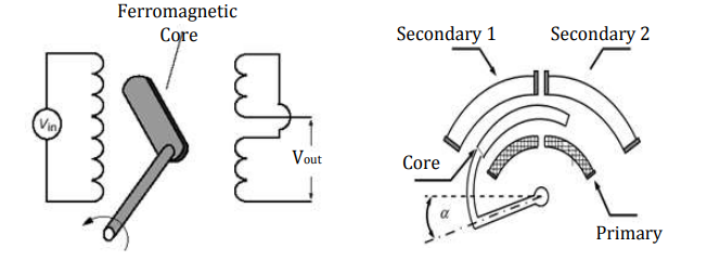
RVDT consist of rotating iron core and one primary excitation coil and two secondary output coils. A fixed alternating current excitation is applied to the primary stator coil that is electromagnetically coupled to the secondary coils. This coupling is proportional to the angle of the input shaft. The output pair is structured so that one coil is in-phase with the excitation coil, and the second is 180 degrees out-of-phase with the excitation coil.
Operation
When the iron core lies at the centre of both secondary, the output differential voltage remains unaffected and has zero magnitude. When the core moves towards secondary-1, it induces more emf across it and less emf across secondary-2. Let’s assume that it is positive displacement. Due to more flux links with the secondary-1 than secondary-2. When the core moves towards secondary-2, it induces more emf across it and less emf across secondary-1. Lt’s assume that it is negative displacement. Due to more flux links with the secondary-2 than secondary-1. The output differential voltage is proportional to the angular motion of the iron core. RVDT has the accuracy of ±1% for rotation upto ±40° and ±4% for rotation upto ±60° RVDT is not advisable to use If rotation is greater than ±60°, RVDT is not advisable to use.
Advantages
- Low sensitivity to temperature, primary voltages & frequency variations
- Low cost & small size & simple control
Disadvantages
- LVDT is sensitive to stray magnetic fields so they always require a setup to protect them from stray magnetic fields.
- They are affected by vibrations and temperature.
III. Strain Gauge
Strain Gauge is used to measure strain on an object. As the object is deformed, the foil is deformed; this causes electrical resistance to change. The change in resistance usually a Wheatstone bridge, is related to the strain by the quantity known as gauge factor.
Principle
It is a sensor whose resistance varies with applied force. It converts force, pressure, tension, weight etc., into a change in electrical resistance which can then be measured.
Construction
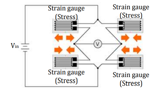
It has resistive elements & can be connected in half bridge and full bridge type. It has various types as following; Bonded & Un-bonded metal wire type, wire type, foil type, frame type, sheath type
Operation
When the load or weight is acting on the strain gauge element, it deforms. The deformation in element causes the change in resistance of it. As per the balance and unbalance condition of the bridge, the voltmeter shows the output voltage. The output voltage is proportional to the change in resistance of the strain gauge elements and that change in resistance is proportional to the weight acting on it. Therefore, the output voltage varies with the weight. The fixed dc voltage source is required for this operation.
Advantages
- High sensitivity to input
- Low cost
- Small size
- Simple control
- Fast response
- Available in wide range
Disadvantages
- They are affected by external vibrations & temperature
- Errors
Applications
- Weight measurement & Die cutting application
- Medical applications
- In torque meters & diaphragm pressure gauge
- In accelerometers & flow meters
- Wire Strain Gauge
The arrangement consists of following parts,
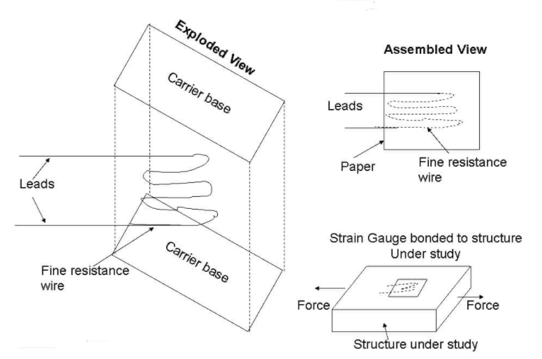
A fine resistance wire diameter 0.025 mm which is bent again and again as shown in diagram. This is done to increase the length of the wire so that it permits a uniform distribution of stress. This resistance wire is placed between the two carrier bases (paper, Bakelite or Teflon) which are cemented to each other. The carrier base protects the gauge from damages. Leads are provided for electrically connecting the strain gauge to a measuring instrument (Wheatstone bridge).
Operation
With the help of an adhesive material, the strain gauge is pasted/bonded on the structure under study. Now the structure is subjected to a force (tensile or compressive). Due to the force, the structure will change the dimension. As the strain gauge is bonded to the structure, the stain gauge will also undergo change in both in length and cross-section (that is, it strained).
This strain (change in dimension) changes the resistance of the strain gauge which can be measured using a wheat stone bridge. This change in resistance of the strain gauge becomes a measure of the extent to which the structure is strained and a measure of the applied force when calibrated.
Fine Wire Strain Gauge Materials
Nichrome Ni- 80%; Cr-20%
Constantin Ni-45%; Cu-55%
Nickel
Platinum
Isoelastic Ni-36%; Cr-8%; Mo-0.5%
Advantages
- The range of this gauge is +/- 0.3% of strain
- This gauge has a high accuracy
- Has a linearity of +/- 1%
Limitations
- This gauge cannot be detached & used again
- Costly
2. Metal Foil Strain Gauge
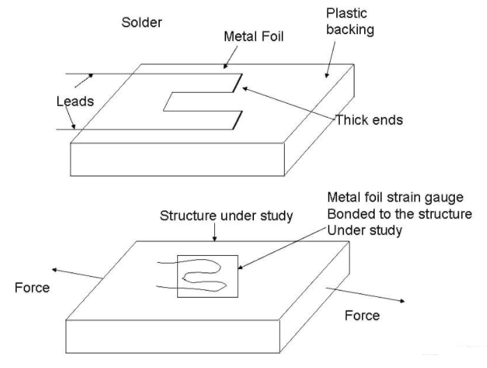
The metal foil of 0.02mm thick is produced using the printed circuit technique. This metal foil is produced on one side of the plastic backing. Leads are soldered to the metal foil for electrically connecting the strain gauge to a measuring instrument (wheat stone bridge).
Operation
With the help of an adhesive material, the strain gauge is pasted/bonded on the structure under study. Now the structure is subjected to a force (tensile or compressive). Due to the force, the structure will change the dimension. As the strain gauge is bonded to the structure, the stain gauge will also undergo change in both in length and cross-section (that is, it strained).
This strain (change in dimension) changes the resistance of the strain gauge which can be measured using a wheat stone bridge. This change in resistance of the strain gauge becomes a measure of the extent to which the structure is strained and a measure of the applied force when calibrated. Same as Fine Wire strain gauge operation.
Advantages
- They can be manufactured in any shape
- Perfect bonding of the gauge is possible with structure under study
- The backing can be peeled off & the metal foil with leads can be used directly on the structure.
- They have better fatigue life
- Has good sensitivity & have stability even at high temperatures.
(3) Semi Conductor Strain Gauge
The sensing element is rectangular filament made as a wafer from silicon or geranium crystals.
To these crystals, boron is added to get some desired properties and this process is called doping and the crystals are called doped crystals.
This sensing element is attached to a plastics or stainless steel backing. Leads made of gold are drawn out from the sensing element for electrically connecting the strain gauge to a measuring instrument (wheat stone bridge).
There are two types of sensing element namely:
- Negative or n-type (resistance decrease with respect to tensile strain).
- Positive or P-type (resistance increase with respect to tensile strain).
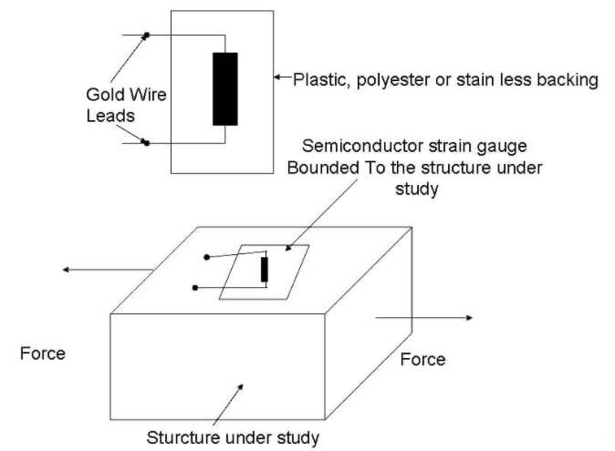
Operation
With the help of an adhesive material, the strain gauge is pasted/bonded on the structure under study. Now the structure is subjected to a force (tensile or compressive). Due to the force, the structure will change the dimension.
As the strain gauge is bonded to the structure, the stain gauge will also undergo change in both in length and cross-section (that is, it strained).
When the sensing element (crystal) of the semiconductor strain gauge is strained, its resistivity changes contributing to a change in the resistance of the strain gauge.
The change in the resistance of the strain gauge is measured using a wheat stone bridge. This change in resistance of the strain gauge becomes a measure of the extent to which the structure is strained and a measure of the applied force when calibrated.
Advantages
- These gauges have high gauge factor and hence they can measure very small strains.
- They can be manufactured to very small sizes.
- They have an accuracy of 2.3%
- They have excellent hysteresis characteristics.
- They have a good frequency of response.
- They have good fatigue life.
Limitations
- These gauges are brittle and hence they cannot be used for measuring large strain.
- The gauge factor is not constant.
- These gauges have poor linearity.
- These gauges are very costly and are difficult to be bonded onto the structure under study.
- These gauges are sensitive to change in temperature.
References
1) R.K. Rajput -“Electrical Measurements and Measuring Instruments” – S. Chand Limited, 2009
2) J.B. Gupta - “ Electrical Measurements and Measuring Instruments ” – S.K. Kataria & Sons
3) E.W. Golding - “ Electrical Measurements and Measuring Instruments ”