UNIT 1
Dielectric properties of insulating materials
While a voltage is applied on the object like an electric conductor that conducts the electricity charges, the conductor becomes charged and forces are beginning to act on other charges in the vicinity. So, there are two types of forces are distinguished-
One arises from the stationary electric charges; this is known as the electrostatic force.
Another is the appears when the charges are moving, known as the magnetic force.
And the filed concept has been developed to explain the existence and spatial distribution of these forces.
And the term static is referred to the situation where all the electric charges are determined in the space, or move as the steady flow, so both of the charges and current densities are constant within time. There is an electric field for fixed charges whose strength at any point in the space relies on values and geometry of all charges.
Dielectric constant
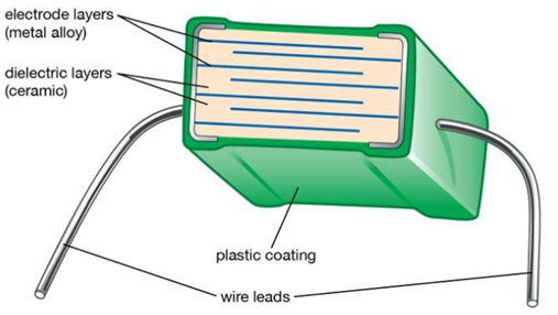
Dielectric constant also named relative permittivity specific inductive capacity, this is a property of the electrically insulating material and also equal of the capacitance of the capacitor filled with the given material of the capacitance of the identical vacuum capacitor without any dielectric material. Between the plates, the insertion of the dielectric, parallel plate capacitor always improves its capacitance, and ability to collect the opposite charges on every plate, also compared with this ability while the plates are separated from the vacuum.
If the capacitance value C filled with given dielectric and CO is the capacitance of the identical capacitor in the vacuum, this dielectric constant symbolized through the Greek letter Kappa, K, and expressed as K=C/CO.
Constant of the dielectric is a number without any dimensions.
In centimeter- gram- second system, the dielectric constant is identical to permittivity. It describes a large scale property of the dielectric without specifying electrical behavior on an atomic scale.
Dipole moment
When the charge is separate in any system the dipole moment arises. So, arise in the ionic bonds as well as in the covalent bonds. When the difference in the electronegativity between two chemical atoms is bonded, dipole moments occur.
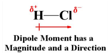
The dipole moment is the measure of the chemical bond polarity between two atoms in a molecule. This is the concept of the electric dipole moment, this the measure of the separation of the positive and negative charges in the system.
Dipole moment formula
Dipole Moment (µ) = Charge (Q) * distance of separation (r)
It is measured by the Debye unit which is denoted by the ‘D’, 1D=3.33564x10⁻³⁰ C.m.
Where C is Coulomb and m is meter.
The bond dipole moment arises in the chemical bond between two atoms of the different type of electronegativities can be expressed as follows-
μ = 𝛿.d
Where μ is the bond dipole moment
𝛿 = magnitude of partial charges 𝛿+ and 𝛿–
And d = distance between 𝛿+ and 𝛿–
Example
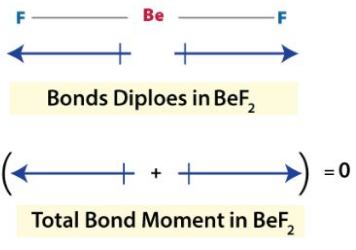
The dipole moment of the Bef2
Polarization
When every unit of dielectric volume has been its electrical moment polarization occurs. There are two kinds of polarization are-
- When it occurs in the electric field.
- Spontaneously
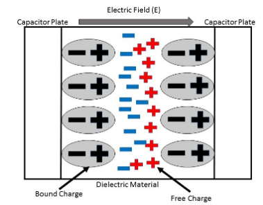
In some cases, mechanical stresses can also reason for the polarization. The dielectric constant is a parameter, qualities of the ability of some polarize materials. The term dielectric polarization explains the behavior of the material while an external electric field id applied to it.

Cd= dielectric capacitance of medium,
C= subscript
O= vacuum dielectric capacitance
Dielectric polarization is followed by coherent charges on the surface of the dielectric. These coherent charges decrease the electric field inside the dielectric. Polarity is the quantitatively defined by the dielectric polarization.
Polarity is the vector quantity and measured by the

Polarizability
This is the measure of the ability of the material to become polarized in the presence of the applied electric field.
Polarization has occurred in polar or non-polar materials.
Polar dielectric
These are made from the polar molecules. The mass center of the +ve charges does not coincide with the mass center of negative charges, in a molecule. When it is in a normal state, means no electric field applied every molecule has been some of the intrinsic permanent dipoles and contains an asymmetric form. The dielectric constant is considered as the permittivity ratio of the substance to free space permittivity. This is an expression of the extent to that a material concentration of the electric flux, is the electrical equivalent of the relative magnetic permeability.
Examples
Ammonia and HCI
Non-polar dielectric
These are made from the non-polar molecules. The center of the mass of +ve charges coincides with the mass center of negative charges in a molecule. When it is in normal state molecules contain zero dipoles and contains the asymmetric form.
Examples
Methane, benzene, etc.
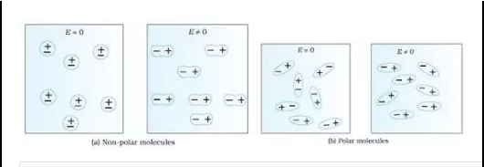
Polarization of mechanism on how to atom or molecule is reacting with the peripheral electric field. This can lead to the positioning of the dipoles. There are 4 types of polarization mechanisms.
Electronic polarization
Iconic or orientation polarization
Interfacial polarization
Iconic polarization
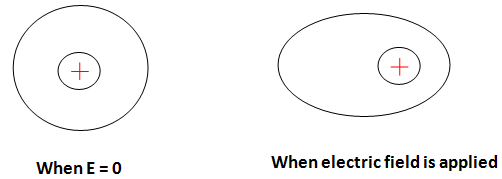
Electronic polarization
In these neutral atoms become polarized and it provides outcomes for electrons shifting. This is also known as the atomic polarization. To understand simply concerning the nucleus, the center of the electron is shifted. The dipole moment is shaped in below-
Orientation or iconic polarization
This is known as the dipolar polarization. The cause of the thermal equilibrium of the atoms, in the normal state dipoles, will be casually aligned. While the peripheral electric field is implemented, it outcomes in polarization. Dipoles will be again to some of the degrees as represented in below figure-
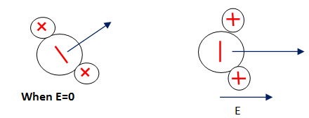
It generally occurs in liquid and gases like HCI, H2O, etc.
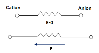
Iconic polarization
It is the ions polarization. It outcomes from the shifting of ions and forms of the dipole moment. It generally occurs in solid materials. For example, NaCl. The normal state has some dipoles and they void each other. It is shown in figure-
Interfacial polarization
This is also known as the space charge polarization. Cause of the peripheral electrical field, at the electrode interface and material the orientation charge dipoles take place. While a peripheral electric field is implemented, some of +ve charges movement to grain the boundary takes place and outcome in the assemblage. This shown in the below figure-
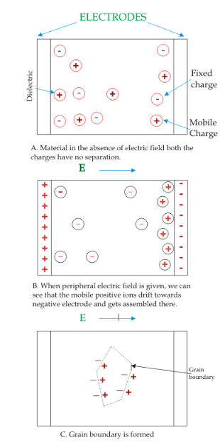
But, mostly one polarization will be present in only material. Also, electronic polarization is happening in almost all the materials.

As discussed above the polarization can be considered as the to arise from the 3 major aspects like electronic, iconic and orientational polarization which is-

So, materials may be categorized into 3 types based on the dielectric behavior of the solids are concerned.
- Elemental solid dielectric
These materials are consisting of single kinds of atoms like diamond and germanium. These all materials have neither ions nor permanent dipoles and so exhibit only electronic polarization.
Internal field Ei dielectric solids show an electric dipole moment P
Which is 
αe= electronic polarizability
n is consider the number of the molecules per unit dielectric volume, then polarization (P) is provided by
P=np
By substituting both equation
P=nαeEi (2)
Ei=E+P/3ε0 (3)
By the both equations put equation (3) in equation (2)
P=nαe[E+P/3 ε0] (4)
If £ is dielectric permittivity, D is displacement is given by
D= εE= ε0E+P
Or P={ ε- ε0)E
Or E=P/ε- ε0 (5)
By using equation (5) in equation (4), get
P=nαe[P/( ε- ε0)+ P/3 ε0]
= nαeP[2 ε0+ ε/3 ε0 (/ε- ε0)
Or 3 ε0/nαe= (ε+2 ε0)/( ε- ε0)
Or (ε- ε0)/(ε+2 ε0)=nαe/3 ε0 (6)
As ε0= εr ε0 (7)
By using equation (7) in (6), get
(εr ε0– ε0)/ (εr ε0+2 ε0)=nαe/3 ε0
Or ε0 (εr-1)/ ε0 (εr+2)= nαe/3 ε0
Or (εr-1)/ (εr+2) = nαe/3 ε0
This is the clausius Mossotti equation.
This equation displays the dielectric constants are determined by the n, αe, and γ.
Here γ=1/3.
These materials are the materials that produce an electric current when these are placed under mechanical stress.
There are three issues which are presently faced within attempting to tap into the piezoelectric as the viable electricity production methods.
- The big problem is that quantity of the electricity which is produced is so small, therefore unless huge installations were set up, it would easily not have the strength of the power of the latest gadgets.
- The present is only generated while there is mechanical stress being applied, therefore as soon as they stop compressing the material, so there is no charge generated.
- The last problem is that up to now, many of the beginning products required to generate piezoelectric materials are toxic and complex to work with.
Piezoelectricity is a pre-existing field of nanotechnology and there are already being tested run outside labs to attempt and harness this power form.
Pyro-electric materials
These materials produce electricity possible whenever cooled or heated. Examples of materials ammonium, quartz crystal, and phosphate. Their properties are unidirectional polarization and non-centrosymmetric.
This exhibits pyroelectricity while T>=Tc
Applications of the pyro-electric materials are IR detectors, temperature sensing components, and image tubes.
Ferro-electric materials
Ferroelectric materials exhibit electric polarization in the absence of an electric field. Examples of the materials lithium niobite and barium titanium. Properties are of these materials are they are both piezoelectric and pyro, easily polarized, and exhibit dielectric hysteresis.
Applications are it works as a memory device such as random-access memory, ultrasonic transducers and these are pressure transducers.
Dielectric loss is energy dissipation by the movement of charges in an alternating electromagnetic field as the polarization switches in direction.
Dielectric loss tangent is defined as the ratio of lossy reaction to electric field E in curl equation to the lossless reactions. For dielectric with the small loss, this angle is <<1 and tan δ ≈ δ.
Tan delta or dissipation factor is explained as reciprocal of the ratio between insulating materials capacitive reactance to the resistance at the specific frequency. The dissipation factor indicates insulation quality materials through the tangent ratio of resistive current IR to the capacitive current IC, negative tan delta factor would indirect a negative resistive current, that is physically impossible.
References
American Society for Testing and Materials. (1967). Measurement of dielectric properties under space conditions. Philadelphia.
Huff, H., & Gilmer, D. (2005). High dielectric constant materials. Berlin: Springer.