UNIT 2
Dielectric breakdown
Dielectric breakdown is failure of insulating material to the withstand an applied electrical stress or electrical field. This can be complete (such as spark break down) or partial (such as corona or series of the partial discharges). It occurs when electrical field become higher enough to reason some of the portion of the dielectric to sudden switch from the being an electrical insulator to the partial conductor. This occur along the interface between 2 dielectric or inside a single dielectric. It is important because intense ionization occurring at branch tips is sub-microscopic and high-speed in size, therefore this cannot be shown directly. Complete form, timing and growth pattern of streamer trees can be recoded. We replicate these features through a detailed probability model, this gives three dimensional graphical results suitable for the comparison against the high-speed shadow photographs provided in experiment.
Ionization
The process of the releasing electron from the gas molecule with the concurrent production of the positive ion is named ionization.
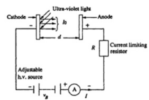
The ionization is reasoned through passing particle is primary ionization, the reason of the ionization is δ rays is the secondary ionization. The amount of the secondary ionization relies on materials, this can be up to the 10 times amount of the primary ionization.
Ionization process by simple collision in gases
When an electron kinetic energy (1/2mu²), in the collision with the neutral gas molecule surpasses ionization energy (Ei = e Vi) of molecule, then ionization occur.
When 1/2mu² > Ei.

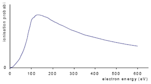
In normally, a +ve ion and two slow moving electron will give result. And the probability of this procedures is 0 for the electron energy equal to ionization energy Ei, however improves the almost linearly at the first and then slowly with the electron energy up to the maximum.
While gas molecules are attacked with the electrons, remaining electrons are bounded to the atoms may be release through collision with higher energy electron. The electrons ratio is provided by the collision to primary electrons rely, mainly on energy of primaries. This is the maximum at the primary electron energies of approximate 200-500 eV. For the lower energy value, energy is transferred may not be enough to reason electrons to get away from surface of molecule, and so the probability of the ionization is small. For the more highest values of the primary energies, impinging electron energy would be enough for this electron pierce the surface extensive into molecular, therefore this again the opportunity of escape of another electrons decrease. So ionization variation probability in air with the improve of the electron energy is shown in the below figure-
2.2.1 Breakdown voltage
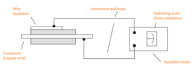
In insulating material atoms are tightly bounded electrons, free electrons are flow every well. But insulators materials cannot repel indefinite amount of the voltage. With applying sufficient voltage is applied, any of the insulating material will be eventually yield in to electrical “pressure”, and the flow of current will occur. But, far from situation with the conductors where current is in linear proportion to the applied voltage which is provided a fixed resistance, through an insulator current is quite nonlinear, for the voltages below a fix threshold, in fact no current will be flow, however if applied voltage is exceeds which threshold voltage and known as breakdown voltage or the dielectric strength, so there will be a current rush. Cause of the dielectric breakdown, dielectric strength is required voltage, which is to force current by an insulating material. After the dielectric breakdown, material may or may not act as an insulator any more, the structure of the molecular having been changed by breach. There is generally a localized “puncture” of insulating medium the current flowed breakdown time. Material thickness of an insulating materials determine its breakdown voltage.
2.2.2 Dielectric strength
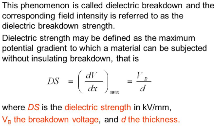
Dielectric strength of the materials is a measurement of electrical strength of an insulator. This is defined as maximum voltage needed to produce a dielectric breakdown by the material and is indicated in terms of the volts per unit materials thickness. The highest dielectric strength of the material the better an electrical insulator it develops. IEC 60243 is a standard mentioned for a way of the testing dielectric strength of the material.
Primary ionization of the gases
By the some external means electrons are produced, when electrons are traveling towards the anode due to the field applied, develop a collisions with the neutral atoms and liberate electrons and +ve ions. The liberated ions develop further collisions and the procedures continue. The electrons and ions constitute the current. This all procedures called primary ionization.
Primary ionization coefficient
Average number of ionizing collisions develop by an electron per centimeter travel the electron in field direction is called town sends first ionization co-efficient. It relies on gas pressure and E/P.
Secondary ionization of gases
The positive ions, time of primary ionization procedures migrate towards cathode. Excited atoms, got the exciting during collision of the starting electrons, emitting the bombard and emission of the secondary electrons from cathode. Photons are that bombard towards cathode and metastable bombard cathode metal surface. Emit the secondary electrons and develops the secondary electrons.
When the secondary electrons free as above make the ionization collision and develop additional electrons. Electrons again develop the ionization collisions and the process is repeats. This is named secondary ionization. This electronic discharge is self sustained cause of the once secondary electron are developed. These are take care of the situation. Where are start electron at the cathode or not ionization proceeds. This is called self sustained the discharge.
Breakdown voltage, this is the minimum applied voltage which would cause a provided insulator or electrode to the breakdown.
Dielectric strength
Dielectric strength is described as electrical strength of an insulating materials. In an enough strong electric filed insulating insulator properties break down allow the flow of charge. Dielectric strength is measured by the maximum voltage needed to develop a dielectric breakdown by a materials. It is explained as volts per unit thickness. Dielectric strength of plastic material varies form the 1 to 1000MV/m. High dielectric strength corresponds to the better insulation properties. ASTM D149 and IEC 60243-1 are standard test process to measure dielectric strength of the materials.
There are factors given below which affects the breakdown in the solid dielectrics
- Ambient temperature
- Impurities, gaseous inclusion, water and moistures
- Permittivity
- Chemical deterioration
- Mechanical strength
There are some factors which are affected by the liquid breakdown strength
Dust
Carbon and sulphur ions
Water particles
Water vapor
Iconic particles
Dissolved gases such as co2
Factors that are affect the breakdown in gases dielectric
When the voltage is applied, large , the current flow by the insulation and increases too sharply and an electrical breakdown happens. Factors are affects in the breakdowns in the gaseous dielectric are
Low dielectric strength, chemical and thermal instability, bad heat transfer and flammability and hazardous.
Unit 02 (B)
- Measurement of dielectric loss tangent (tan δ) by schering bridge-IS 13585-1994.
AIM
Measurement of dielectric loss tangent ( tan delta) by Schering Bridge.
Apparatus:
Sharing bridge kit, Digital multimeter, Patch cords,
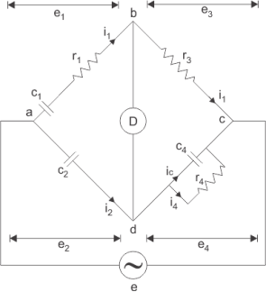
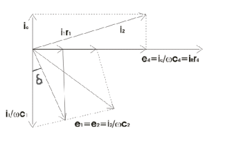
Procedure and theory
When time varying electric field, current density Jc is utilizing ampere law is given by

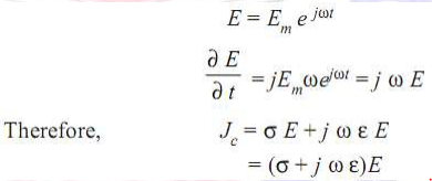
In general for harmonically varying field, conduction losses, polarization losses, and ionization also happen and so the dielectric constant ε = ε0 εr is longer, real quantity rather it is a complex quantity. Dissipation factor tan δ is ratio of real component of the current Iω to the reactive component Ir.

Here, δ is angle between reactive component of the current and total current flow through dielectric at the fundamental frequency. While δ is too small tan δ= δ.
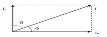
Dielectric loss keeps three components corresponding to three loss of mechanism. Pdiel=Pc+Pp+Pi and for an individual dissipation factor can be given like that tan δ= tan δc+ tan δp+ tan δi when only the conduction losses occur then


This provide information that dissipation factor due to the conduction loss alone is inversely proportional to frequency and can, be neglected when frequencies is high. But for the supply frequency every loss component will have been considerable magnitude. When all losses are include and existence of the loss current in addition to charging current through introducing the typical permittivity.
ε* = ε′ – j ε″
Total current I

C0 is the capacitance without any dielectric material.
For parallel circuit dissipation factor is given by

For series cuircuit
Tan δ = ω Cs Rs
For getting fixed frequency both equivalents hold the good and one can be acquired from other. But, frequency depend is just opposite in two cases and this provide limited validity of the equivalent circuits.
The information about the tan δ and complex permittivity is indication of quality of insulating materials.
- If tan δ is varies and changes with application of the high voltage, it shows internal inception of the partial discharge.
- Effect of the frequency on dielectric properties can be described and frequencies band where the dispersion occurs, where permittivity reduce with the rise in the frequency can be acquired.
2. Measurement of dielectric strength of solid insulating material-IS 2584.
AIM
To Measure Electric strength of solid Insulating Materials.
APPARATUS
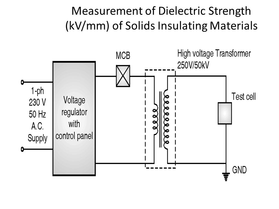
Test cell For Solid Breakdown, Single Ph 230v 50 Hz AC supply, MCB, High
Voltage Transformer.
Theory
Which is the basic breakdown mechanism in the solid dielectric materials?
Which are the various factors upon which the breakdown strength depends?
What is the need of the high voltage transformer?
Circuit diagram
Process
Make sure that oil level must be high enough so which both electrodes fully immersed in oil.
Make sure which there is physical contact of the H.V electrode with solid insulating materials.
Make sure that there is no sharp point at point of the connection between H.V bushing and H.V electrode of test cell set up.
Make sure that test cell is appropriately connected to ground.
Increased voltage at proper rate of the 2KV/sec. Note down exact value of the break dwon voltage.
Observation table
Sr. No | Solid Dielectric | Break Down Voltage(KV) | Thickness(mm) | Breakdown strength(KV/mm) | Mean Dielectric Strength |
1 |
|
|
|
|
|
2 |
|
|
|
|
|
3 |
|
|
|
|
|
4 |
|
|
|
|
|
5 |
|
|
|
|
|
Results
The Breakdown strength of solid insulating materials is…………….. KV/mm.
3. Measurement of the dielectric strength of liquid insulating material –IS 6798.
AIM
To Measure Dielectric strength of Liquid Insulating Materials.
APPARATUS
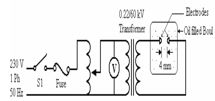
Test cell For Liquid Breakdown, Single Ph 230v 50hz AC supply, MCB and High Voltage Transformer.
Theory
Which is various theory for the liquid breakdown?
Which are various factors upon which breakdown strength depends?
What is the effect of the gap distance upon break down strength of the oil?
Circuit diagram
Procedure
Make sure that oil level must be high suffiecient so which both electrodes fully immersed in oil.
Apply the high voltage to the HV terminal to the test cell.
Make sure that test cell is appropariatley connected to ground.
Voltage is increased at the appropriately rate of the 2KV/sec. Note down the accurate value of the break down voltage.
OSERVATION TABLE:
Gap between electrodes is 2.5 mm
Sr. No. | Liquid Dielectric | Break Down Voltage(KV) | Breakdown strength(KV/mm) | Mean dielectric Strengh |
|
|
|
|
|
|
|
|
|
|
|
|
|
|
|
|
|
|
|
|
|
|
|
|
|
Result
The Breakdown strength of Liquid insulating materials is…………….. KV/mm
Conclusion
Break down strength of the oil is increases with the increment of the gap distance between electrodes. Impurities like gas bubbles solid fibrous particles remove the breakdown oil strength.
4. Measurement of dielectric strength of gaseous insulating material as per IS.
AIM
To Measure Dielectric strength of gaseous Insulating Materials.
APPARATUS
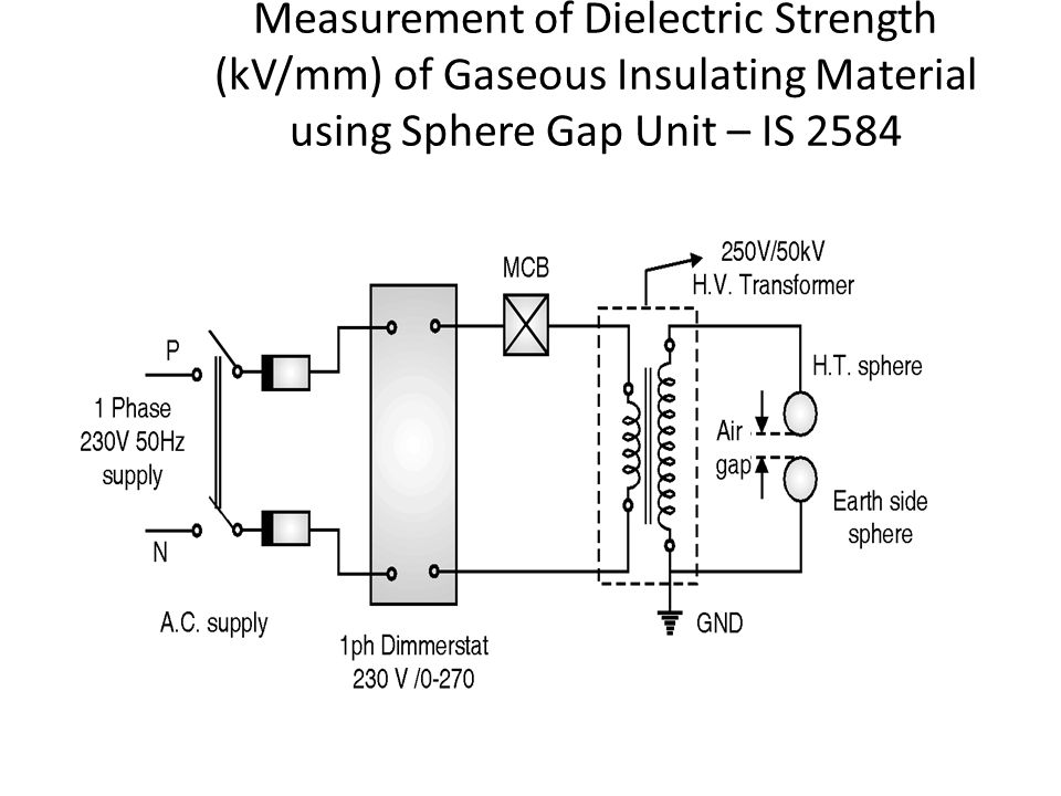
Test cell for gaseous Breakdown. Sphere gap unit), Single Ph 230v 50 Hz AC supply, MCB High Voltage Transformer.
Theory
Which is the various mechanism for the breakdown in gases?
Which are the various factors upon which the breakdown strength depends?
What is effect of the gap distance upon the break down strength of the gases?
Circuit
Processes
Connect with the HV terminal of transformer to upper sphere of the sphere gap unit and connect with the earth terminal corresponding to the lower terminal.
Apply the high voltage to upper terminal.
Hissing noise due to air ionization. At the specific voltage which is depending on environment condition appears sparks which is breakdown happens between 2 sphere. Note this voltage.
Repeat the procedures and note down readings.
OSERVATION TABLE:
Gap between the electrodes is 2.5mm
Sr. No | Gap between spheres in mm | Dielectric strength (KV/mm) |
1 |
|
|
2 |
|
|
3 |
|
|
4 |
|
|
Result: The Breakdown strength of gases insulating materials is…………….. KV/mm
Reference book
Whitehead, D. (1953). Dielectric breakdown of solids. Oxford: Oxford University Press.
Gaxiola, E. (1999). Dielectric breakdown in insulating gases. Eindhoven: Technische Universiteit Eindhoven.