Unit 5
Solar Energy
Solar Radiation at the Earth’s Surface-
Solar radiation is received at the earth’s surface in an attenuated form because is subjected to the mechanism of absorption and scattering as it passes through the earth’s atmosphere.33
Absorption occurs primarily because of the presence of ozone and water vapors in the atmosphere and to a lesser extent due to other gases (like ).
).
It results in an increase in the internal energy of the atmosphere.
The scattering occurs due to all gaseous molecules as well as particulate matter in the atmosphere.
The scattered radiation is distributed in all directions same going to back into space and some reaching at the earth’s surface.
Solar radiation received at the earth’s surface cut in out change of direction i. e. line called beam or direct radiation.
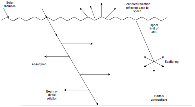
Fig 1: Schematic representation of
The mechanism of absorption and scattering and
Beam and diffuse radiation received at earth’s surface.
The radiation received at the earth’s surface from all parts of the sky’s hemisphere. (After being subjected to scattering in the atom) is called diffused radiation.
The sum of the beam and diffuse radiation is referred to as total or global radiation.
The rate at which solar energy arrives at the top of the atmosphere is called Solar constant ( ).
).
This is the amount of energy received in unit time on a unit area perpendicular to the sun’s direction at the mean distance of the earth from the sun.
Because of the sun’s distance and activity vary throughout the year; the rate of annual of solar radiation varies accordingly.
The so called solar constant, actual values vary up to about 3% in either direction.
Solar constant for earth is 1.353 kilowatts per square meter or 1357 watt per square meter.
The table below gives standardized values of solar constant for various planets.
Planet | Distance (  | Solar constant  |
Mercury | 57 | 9228 |
Venus | 108 | 2586 |
Earth | 150 | 1357 |
Mars | 227 | 586 |
Jupiter | 778 | 50 |
Solar Constant  -
-
The solar constant is defined as the energy released from the sun per unit time on the unit are of the earth surface, perpendicular to the direction of propagation of the radiation (at earths mean distance) from sun outside the atmospheric.
The latest value of  is 1395w/
 .
.
World radiation center (WRC) has adopted the value of I(on)= 1367w/ Based on the solar constant the total solar energy incident on the entire globe of earth can be calculated.
An approximate equation relating the variation of sinusoidal solar constant with time of the year is given as

Where,
Ion=Actual sinusoidal radiation measured on the plane normal to radiation
Isc=Solar constant taken as 1353w/ .
.
n = days of the year.
Concentration ratio (c):
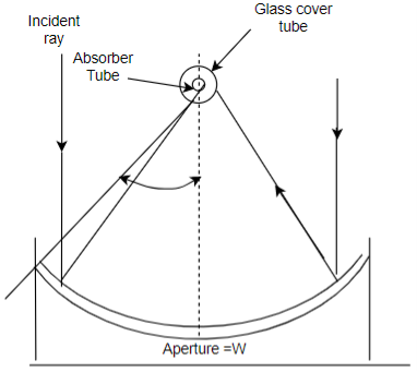
w = Aperture.
L = Length
 r =Rim angle
 = Outer diameter of absorber tube


Cloudy index

Measurement of Solar radiation is important because of the increasing number of solar heating and cooling applications and the need for accurate solar irradiation data to predict performance.
Two basic types of instruments are employed for solar radiation measurement: -
Pyrheliometer-which collimates the radiation to determine the beam intensity as a function of incident angle.
Pyranometer-which measures the total hemispherical solar radiation. The Pyranometer measurements are the most common.
1. Pyrheliometer-
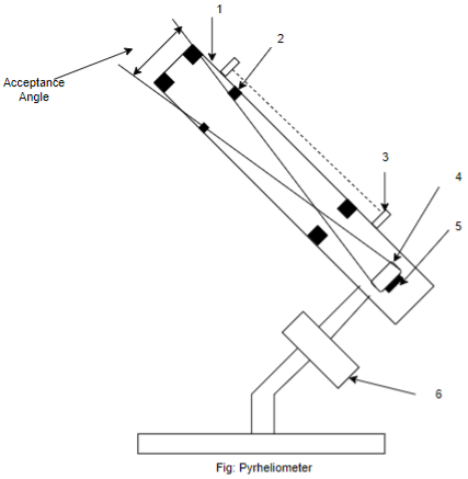
A Pyrheliometer is an instrument which measures beam radiation.
The Sensor disc is located at the base of a tube whose axis is aligned with the direction of the sun’s rays. Thus differs radiation is essentially blocked from the sensor surface.
The black absorber plate (with the hot junction of a thermopile attached to it) is located at the base if a collimating tube.
The tube is aligned with the direction of the tube sun’s rays with the help of a two axis tracking mechanism and an alignment indicator.
Thus the black plate receives only beam radiation and a small amount of diffuse radiation falling within the ‘acceptance Angle ‘ of the instrument.
Three types of Pyrheliometer have been use of measure normal incident beam radiation:
a) Angstrom Pyrheliometer
b) Abbot Silver disc
c) Eppley Pyrheliometer
2. Pyranometer:
A Pyranometer is an instrument which measures total or global radiation over a hemispherical field of view.
If a shading ring is attached, the beam radiation is prevented from falling on the instrument sensor and then measures only the diffuse radiations.
In most Pyranometer, the sun’s radiation is allowed to fall on a black surface to which the hot junction of a thermopile are attached.
Pyranometer consists of a black surface which heats up when exposed to solar radiation.
Its temperature increases until the rate of heat gain by solar radiation equals the rate of heat loss by convection, conduction and irradiation.
The hot junctions of a thermopile are attached to the black surface, while the cold junctions are located under a guard plate so that they do not receive the radiation directly.
As a result, an emf is generated. This emf which is usually in the range of 0 to 10mV can be read, recorded or integrated over a period of time and is a measure of the global radiation.
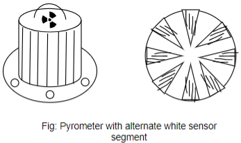
Fig – Pyranometer with alternate black and white sensor segments.
The Pyranometer shown in Fig is used commonly in India. It has its hot junctions arranged in the form of a horizontal circular disc of diameter 25mm and coated with a spherical black lacquer having a very high absorbituity in solar wavelength region.
The Pyranometer can also be used for the measurement diffuse radiation. This is done by mounting it at the centre of a semicircular shading ring.
The shading ring is fixed in such a way that its plane is parallel to the plane of the path of the sun’s daily movement across the sky and it shades the thermopile element.
Comparison between Pyrheliometer and Pyranometer
Pyrheliometer | Pyranometer |
Pyrheliometers measure beam radiation. | Pyranometer total radiations and can be modified to measure only diffuse radiation. |
The sensor disc is placed at the bottom of the tube whose axis is aligned to the sun rays. | The Sensor disc is placed with hemisphere field view. |
Pyrheliometers must track the sun to obtain beam radiations. | They do not require sun tracking. |
Collimators tubes are installed in pyrheliometers avoid diffuse radiation. | There is no Collimator tube to restrict the entry of radiations. |
The radiations falling on the sensor have a regular cone angle of about only 5%. | However, a shading ring may be installed to measure diffuse radiations only. |
The different types of pyrheliometers are: a) Angstrom b) Abbot Silver c) Eppley | The different types: a) Eppley, b) Yellow Solarimeter c) Moll-Gorczyneski d) Bimetallic action graph e) Thermoelectric, etc., |
It is a device which is used for collecting and absorbing the solar radiations on the surface called as absorber.
It transfers the part of gradient energy to the fluid like water or air in contact with it.
The surface of the collector (absorber) is defined for high absorption and low emissions.
Types of solar collectors
Flat plate solar collectors
These collectors are used for low temperature applications i.e up to 100 .
.
If the working fluid for absorbing heat energy is liquid such collectors are called as liquid flat plate collectors
Flat-Plate collectors are used for temperature application
Examples: Space heating and cooling Drying, low temperature, power generators.
Concentrating type collectors;
These are also called as focusing collectors.
These are used for medium to high temperature applications.
Cylindrical Parabolic collectors:
It is suitable for the applications in the range of 100 to 300
 .
.
Vapour engine and turbines
Process heating in industries.
Cooking
Refrigeration
Paraboloid:
This is high temperature arrangement (gives temperature above 200  ). It can be used for steam engines and turbines, sterling engines and thermo-electric generator.
These are passive type solar dryers, which do not use any external power for running a fan or blower.
Cabinet type solar dryer:
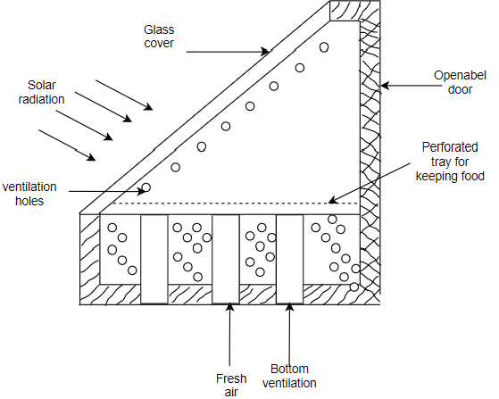
It has an enclosed cabinet having transparent glass covers at the top and insulation is provided at the bottom.
The perforated tray is provided for keeping the food.
The inner surface of the cabinet is coated black and door is provided at the rear of cabinet.
Ventilation holes are provided at the bottom for fresh air to enter the ventilation holes are also provided on the upper side of the dryer for hat moist air to escape by natural convection.
When hot air leaves on the upper holes, a partial vacuum is created bottom holes thus setting up natural convection.
Temperatures range 50 t0 80 are usually attained in the dryer 2 to 7 days depending on the type of food product.
Solar distillation:
The device which is used to convert saline water into pure water by using solar energy is called as solar, still generally known as “basin type solar still”.
It is a shallow basin with blackened surface called basin liner.
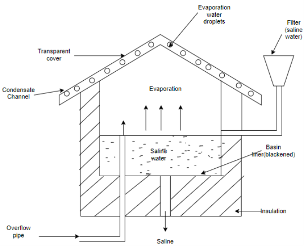
The saline water is supplied to the basin by filler
A overflow pipe allows excess water to flow out from the basin
The top of the basin is covered with a sloping air tight transparent cover that encloses the space above the basin.
The cover is made of glass or plastic the cover is roof like and the slope is provided toward a collection on trough.
Solar radiations are passed through the glass cover and these radiations are absorbed and converted into heat by the basin liner.
The saline water is then heated and water vapour is produced inside the solar still.
The water vapours come in contact with cooler vapour interior surface of the transparent cover and it gets condensed.
The condensed water vapour flows down the slopping roof and it is collected in a tray trough as distilled water.
The efficiency of solar still can be expressed as
Efficiency, 

Where,
m = mass of distilled water produced  day.
day.
 Enthalpy change of inlet cold water to water vapour
H = Intensity of solar radiations per  area/day, ks.
Solar cooking
A major portion of energy per year is consumed for cooking especially in rural areas.
The important application of solar energy is that of cooking solar cooker is a box type cooker having typical external dimensions as 60cm 60cm
60cm 20cm which can cook 4 dishes at a time.
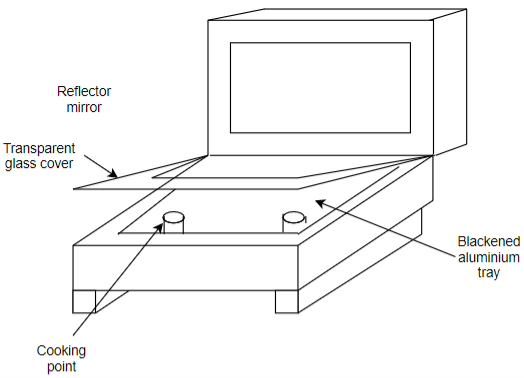
It consist of a rectangular enclose insulated on the bottom and sides.
The top surface of the box is made of blackened aluminum sheet and contains shallow utensils for heating the food to be cooked.
It has one or two glass covers on the top. The top cover has a mirror at required angle hinged on one side. It can be adjusted by guides.
The box receives the direct radiations from sun and also the reflected radiations from the mirror.
The glass cover traps the heat inside the box due to greenhouse effect.
The air temperature is in the range of 100 to 140
 can be obtained in these cookers on sunny days. It is enough to cook the boiling type food like rice, pulses, vegetables etc. it takes about 2 to 3 hrs to cook the food.
Comparison between Flat-Plate Collector and Concentric Solar Collector-
Flat – Plate Collector | Concentric Solar Collector |
Fluids temperatures upto 100  | Fluid temperature can reach upto 500  |
Suitable for low temperature applications like water and space heating | Suitable for power generation
|
Cost is low | Cost is high |
Heavy in weight | Lighter in weight |
Collector efficiently is low. | Collector efficiently is comparatively high |
Heat losses are high due to high collector are | Heat losses are low due to less collector area. |
It has negligible maintenance cost | High maintenance cost. |
In case of solar thermal power plants, the solar energy is first collected by using solar ponds, solar flat plate collectors, etc. The collector solar energy is transferred either directly to the working fluid or to the heat exchanger to operate a power plant.
Advantages of solar thermal power plants:
It saves costly depleting fossil fuels.
It is a pollution free
Do not require fuel transportation
Can be installed for away from fuel sources and in remote areas.
Disadvantages of solar thermal power plant:
Cost of power generation is high
Needs standby power
Need very large collector area for installation
Cannot supply continuous electric power
Only suitable where favourable sunshine conditions are available.
Low thermal efficiency
Needs thermal storage system.
Types of solar thermal power plant:
Low temperature solar power plant using flat-plate collector
Medium temperature solar power plant using power plant concentrator solar collector.
High temperature solar power plant using tower system
Low temperature solar power plant using flat-plate collector solar power system
Since the water can be only heated 80 in flat plate collectors the system needs to use a working fluid having low temperature like a butane gas.
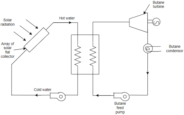
The system consists of an array of flat plate collectors. The cold water is circulated into the collector with the help of a circulating pump.
The water gets heated in the solar collector due to solar radiations upto a temperature of about 80 .
.
The heated water is circulated in a heat exchanger called butane boiler, where it generates the butane gas at high pressure
The butane gas is supplied to butane turbine to produce mechanical power due to expansion of butane gas.
The vapour coming out of the turbine is condensed in a condenser and sent back for recirculation with the help of butane feed pump.
Medium temperature solar power plant
This systems employ an array of parabolic trough concentrating collectors spread over a large area. The general range of working temperature are between 250 to 400 .
.
This system work on Rankine cycle
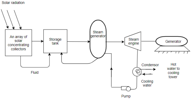
This system consist of an array of large parabolic trough collector duty installed with sun tracking device to collect the solar radiations which is used to heat the fluid.
This heat is transferred to storage tank and finally to feed water where the steam is generated in the steam generator
This steam is utilized to run a turbine coupled to a electric generator. The turbine is converted into electric power by the generator.
The exhaust of steam turbine is condensed in a condenser with the help of cold water circulated in the condenser.
The hot water leaving the condenser is either sent to cooling tower or its heat energy can be used as process heat if the plant is used in an industry.
High temperature solar thermal power plants
For efficient utilization of solar energy into electrical energy, the working fluid has to be supplied at high temperatures large power plants can be built in the capacity of 50Mw to 200Mw.
1) Solar thermal power plant using dish collector
The solar dish collectors receive solar radiations which are collected at a common focusing point.
Small volumes of the fluid are heated at this point to high temperature.
This heat is utilized to run a prime mover based on the sterling cycle
Due to limitations of size and small quantity of fluid, dish type solar power plants are not suitable for generation of power beyond few Kw.
2) Central tower receiver power plant using heliostats
Such power plants use central tower receiver
It uses an array of plane mirrors called heliostats which are individually controlled and tracked to reflect the solar radiations an a receiver kept on a tower of about soon height
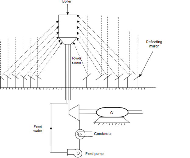
The feed water in the boiler is converted into high temperature steam about 600 - 700
- 700 .
.
This steam is supplied in a conventional steam power plant coupled to an electric generator to generate electrical power as shown.
Solar Photovoltaic system:
In solar photovoltaic system solar energy is directly converted to electric power.
Advantages:
It converts solar energy directly into electrical energy without having to go through other terminal thermal processes
Solar cells are reliable, molecular, durable and generally maintenance free
These are compatible with all environments and their response is instantaneous.
Can be installed at the place of utility, hence avoids the problem of transmission of power as in case of conventional and solar power system.
Grater amount of flexibility in power capacities and hence selection is very easy.
They are more long lasting with stable performance for a life span of more than 20 years or more.
Disadvantages:
Conversion efficiency of solar cells are very low and is of the order of only 30%.
Larger area is needed to generate sufficient power
Solar cell materials are very costly
Solar energy is intermittent. It varies with place and time of the day and ay of the year.
Pair of positive and negative charges called electron hole pairs are created in the solar cell by absorbed solar radiations.
The suitable materials for absorbing energy of photons of sunlight are semiconductors like silicon, gallium and arsenide with dopants.
In a semiconductor the valence band has electrons at lower level of energy which is fully occupied.
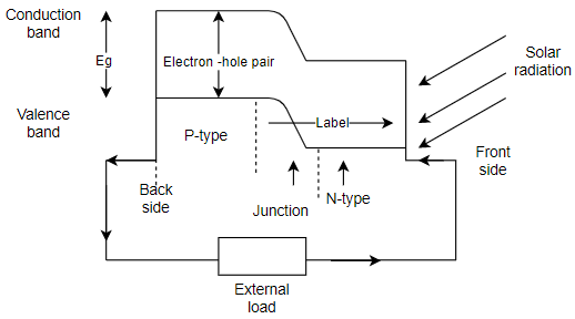
Comparatively, electrons at conduction band have higher level of energy and they are not fully occupied.
The difference in the minimum energy of electrons in conduction band and the maximum energy electrons in valence band is called band gap energy 
When solar energy fall, the difference of photon energy of sunlight, E and the band gap energy,  are absorbed by the cell material it excites some of the elements and they jump across the band gap across valence band to conduction band.
It leaves behind holes in the valence bands therefore electron holes pairs are created.
Therefore electrons in the conduction band can be made to flow in an external circuit if the potential difference exists within the cell.
Energy of photon is proportional to the frequency of radiation

Where
 Photon energy
 Planck’s constant
 Frequency of radiations
 Speed of light (
 )
)
 Wavelength radiations in
A simple equivalent circuit model for a photovoltaic cell consists of a real diode in parallel with an ideal current source as shown in figure. The ideal current source delivers current in proportion to the solar flux to which it is exposed.
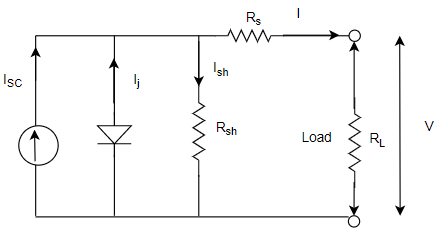
 Supply current from source
 Internal shunt resistance
 Internal sense resistance
 Junction current at p-n junction
 Current passing through the load having resistance
 Voltage drop across the load.
i) Since the internal series resistance ( ) is negligible compared to load resistance
  due to load, the power loss in series resistance can be neglected.
Ii) Usually the shunt resistance much higher than the load resistance  .
.
Iii) Therefore, the current  is negligible and most of the current passes through the load.
I –V Curve for a Photovoltaic Cell-
Numerical-1 Consider a 100  photovoltaic cell with reverse saturation current
 . In full sun, it produces a short-circuit current of
  at 25◦ C. Find the open-circuit voltage at full sun and again for 50 % sunlight.
Solution-
The reverse saturation current I0 is  .
.
At full sun  is
is 
The open-circuit voltage is


Since short-circuit current is proportional to solar intensity, at half sun  and the open-circuit voltage is


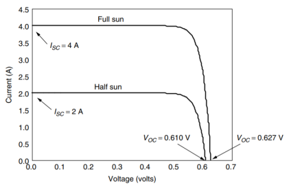
Voltage and Current from a PV Module-
Numerical-2 A PV module is made up of 36 identical cells, all wired in series. With 1-sun insolation ( ), each cell has short-circuit current
  and at 25◦ C its reverse saturation current is
  . Parallel resistance is
  and series resistance
 .
.
a. Find the voltage, current, and power delivered when the junction voltage of each cell is 0.50 V.
Solution-
Using Vd = 0.50 V in along with the other data gives current:


Under these conditions the voltage produced by the 36-cell module:


Power delivered is therefore


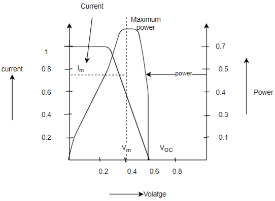
The load might be a dc motor driving a pump or it might be a battery, for example. Before the load is connected, the module sitting in the sun will produce an open-circuit voltage Voc, but no current will flow.
If the terminals of the module are shorted together (which doesn’t hurt the module at all, by the way), the short circuit current Isc will flow, but the output voltage will be zero.
In both cases, since power is the product of current and voltage, no power is delivered by the module and no power is received by the load. When the load is actually connected, some combination of current and voltage will result and power will be delivered.
At the two ends of the I–V curve, the output power is zero since either current or voltage is zero at those points.
The maximum power point (MPP) is that spot near the knee of the I–V curve at which the product of current and voltage reaches its maximum.
The voltage and current at the MPP are sometimes designated as Vm and Im for the general case and designated VR and IR (for rated voltage and rated current) under the special circumstances that correspond to idealized test conditions.
Impacts of Temperature and Insolation on I–V Curves-
As insolation drops, short-circuit current drops in direct proportion. Cutting insolation in half, for example, drops Isc by half. Decreasing insolation also reduces Voc, but it does so following a logarithmic relationship that results in relatively modest changes in Voc.
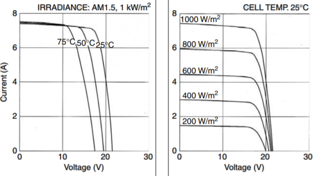
As cell temperature increases, the open-circuit voltage decreases substantially while the short circuit current increases only slightly. Therefore Photovoltaic performs better on cold, clear days than hot ones.
Cells vary in temperature not only because ambient temperatures change, but also because insolation on the cells changes. Since only a small fraction of the insolation hitting a module is converted to electricity and carried away, most of that incident energy is absorbed and converted to heat.
The system designers take in to account for changes in cell performance with temperature. Therefore manufacturers provide an indicator called the NOCT, which stands for nominal operating cell temperature.
The NOCT is cell temperature in a module when ambient is 20◦ C, solar irradiation is 0.8  , and wind speed is 1 m/s.
Shading Impacts on I–V curves-
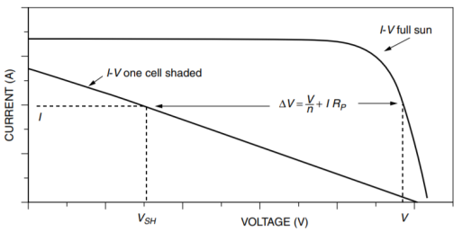
The output of a PV module can be reduced dramatically when even a small portion of it is shaded. Even a single shaded cell in a long string of cells can easily cut output power by more than half.
External diodes, purposely added by the PV manufacturer or by the system designer, can help preserve the performance of PV modules.
The main purpose for such diodes is to mitigate the impacts of shading on PV I –V curves. Such diodes are usually added in parallel with modules or blocks of cells within a module.
In Figure a, all of the cells are in the sun and since they are in series, the same current I flows through each of them.
In Figure b, the top cell is shaded and its current source ISC has been reduced to zero. The voltage drop across  as current flows through it causes the diode to be reversed biased, so the diode current is also zero. That means the entire current flowing through the module must travel through both
  and
and  in the shaded cell on its way to the load. That means the top cell, instead of adding to the output voltage, actually reduces it.
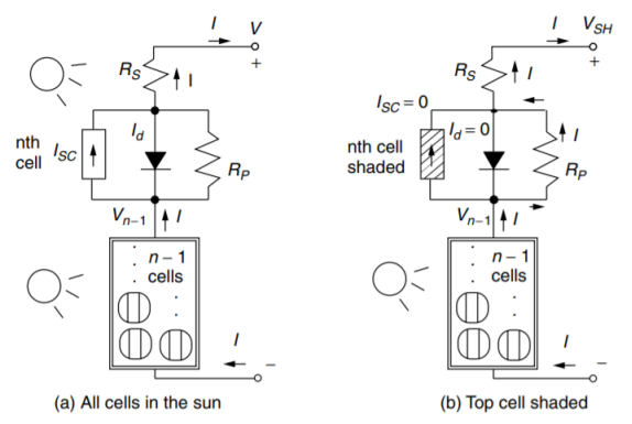
Consider the case when the bottom n − 1 cells still have full sun and still somehow carry their original current I so they will still produce their original voltage . This means that the output voltage of the entire module
  with one cell shaded will drop to

With all n cells in the sun and carrying I, the output voltage was V so the voltage of the bottom n − 1 cells will be


The drop in voltage  at any given current I, caused by the shaded cell is given by,


Since the parallel resistance  is so much greater than the series resistance

At any given current the I –V curve for the module with one shaded cell drops by .
.
System: Introduction to the Major Photovoltaic System Types-
Types of major photovoltaic systems
a) Standalone system
b) Grid connected system (interactive).
A] Standalone system
Characteristics:
The supply power to a system independently without use of any common grid or connection to any other system.
Operates autonomously and independently
Commonly used for backup powers where connecting to grids are very costly.
May or may not use energy
Can be used to power DC loads also the AC loads using inverter.
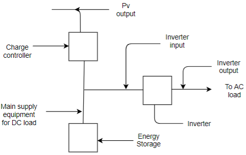
Standalone system has following types
Direct coupled standalone system
Standalone system with batteries
Standalone system with batteries and charge control
Standalone system with AC and DC load.
Hybrid standalone systems.
B] Grid connected system:
In this system the power generated by the pv array is given to the grid or to AC loads directly.
When the power generation exceeds the requirements of loads it is supplied to a commercial grid.
Thus the system forms a part of large network.
The output from the inverter has to satisfy the norms in terms of the quality of the electrical standard so that it can match with grid system.