UNIT 2
Transformers; Three Phase Transformers
The polarity test of a transformer can be done by measuring only voltage at no load. The basic connections are shown in below circuit.
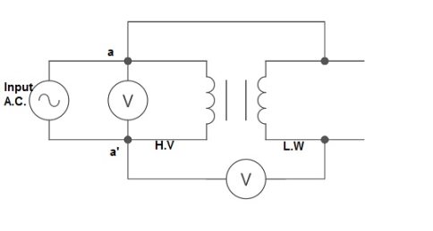
Fig. 1: Polarity Test
From above circuit input is applied for one winding. There is another voltage ‘V’ measured between one winding from each terminal. If voltage V’ > V, polarity is additive. If voltage V’ < V, polarity is subtractive.
If the present transformers are not capable of supplying any amount of additional load which is required, then the parallel connections are used to fulfil the requirement. The basic circuit for parallel transformer is shown below.
The condition required for parallel connections:
- The primary windings of the transformer should be suitable for supply voltage and frequency.
- The connections w.r.t. Polarity of transformer should be proper.
- The voltage ratings of both primaries and secondaries should be identical.
- In order to avoid circulating current the ratio X/R and percentage impendences should be equal in magnitude.
- The transformer that have different KVA ratings should have equivalent impendences inversely proportional to individual KVA rating.
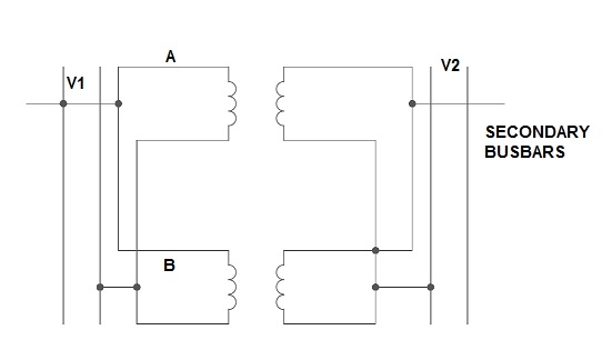
Fig. 2: Parallel Connection of 1-ØTransformer
Key takeaway
The voltage ratings of both primary and secondary should be identical.
1) Ideal Case:
Here both the transformers are considered to have same voltage ratio and impedance voltages triangles identical in size and shape.
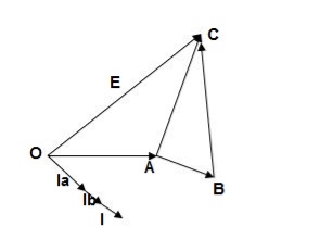
Fig. 3: Phasor for ideal Case
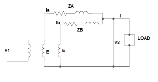
Fig. 4: Ideal Case
I = IA + IB
V2 = E - IAZA
IAZA = IBZB
IA = 
IB = 
E – No load secondary voltage
V2 – Terminal voltage
IA, IB – Currents of each Transformer
2) Equal Voltage Ratio:
Let No-load voltage of each secondary be same E = EA = EB. The change in the secondary is shown below.
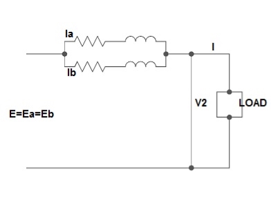
Fig. 5: Equal Voltage Ratio
All values are considered referred to the secondary.
ZA, ZB = impedances of transformer
IA, IB = currents of transformer
V2 = common terminal voltage
IAZA = IBZB = IZAB
ZAB = ZA || ZB
ZA = IZABZA,
IA = 
V2IA = 
V2IB = 
Let V2I × 10-3 = S (Combined Load KVA)
SA = 
SB = 
3) Unequal Voltage Ratios:
Here the no load secondary voltages are unequal.
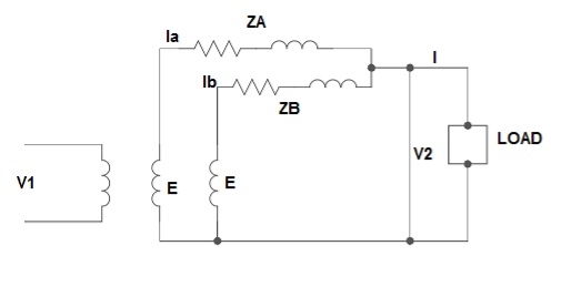
Fig. 6: Unequal Voltage Ratios
EA, EB = no-load secondary emp
Z1 = load impedance across secondary.
Here circulating current exist as the voltage are unequal (IC).
IC = 
EA = IAZA + V2
EB = IBZB + V2
V2 = IZL = (IA + IB)ZL -----------------(1)
EA = IAZA + (IA + IB)ZL -----------------(2)
EB = IBZB + (IA + IB)ZL -----------------(3)
EA – EB = IAZA – IBZB
IA = 
If ZA and ZB are smaller than ZL.
Substitute IA in equation (3) and solve
IA = 
IB = 
Neglecting ZA ZB in comparison with ZL(ZA + ZB)
We get above equations.
I = IA + IB
I = 
V2 = EA - IAZA and V2 = EB – IBZB
Key takeaway
SA = 
SB = 
I = 
V2 = EA - IAZA and V2 = EB – IBZB
These transformers are used in AC machines to change the a.c. Current from the line into a low-voltage, high amperage current in the secondary winding.
Que 1. Two 1-Ø transformers A and B rated at 200 kVA each are operated in parallel on both sides. % impedance for A and B are (1 + j5) and (1.2 + j4.8) respectively. Calculate load showed by each when total load is 500 kVA at 0.8 lagging?
→ 
= 
= 0.507 ∠1.34˚

= 0.49 ∠-1.38˚
Finding combined load
SA =  = 500∠ -36.9˚ × 0.49∠ -1.38˚
SA = 245∠ -38.28˚
SB =  500∠-36.9˚ × 0.507∠1.34˚
= 253.5∠ -35.56˚
Transformer B is overloaded (253.5 - 200) × 
= 26.75 %
Que 2. Two 1-Ø transformers, one of 800 kVA and 400 kVA are connected in parallel to the same bus bars on primary side. Their no load secondary voltage 500 V and 510 V respectively. The impedance voltage of first is 8% and that of second is 5%. Assume ratio of resistance to reactance is same and equal to 0.4 in each. Calculate the cross current when secondaries are connected in parallel?
→ The X/R is same for both, hence they do not have any phase difference.
Let secondary be 480 V
For full load IA = 800 ×  A
A
IB = 400 ×  A
A
ZA = 
ZB = 
The cross current is given as
IC =  A
A
Star – star or Y/Y connection: -
The below figure shows transformers connected in Y/Y on both primary and secondary sides. The ratio of line voltage and transformation ratio of line voltage and transformation ratio of both primary and secondary of each transformer in same. Hence the phase voltage VP =  . VLine (line voltage)
This connection works only if the load is balanced.
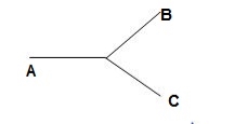
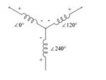
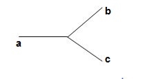
Fig. 7: Three phase transformer Y-Y connection
- The effect of unbalanced load can be balanced by placing single load between a and n on secondary.
- Power to load is supplied by primary side A.
- As, A is in series with B and C and has b and c open on secondary, so it cannot supply required power.
- Now, B and C acts as high impedance in this condition, allowing very less flow of current in A.
- A low resistance can be connected between a and n which is approaching to short circuit. So, small current flows.
- Hence, EAN will reduce to zero but EBN and ECN will rise to full primary line voltage.
- The above shown connection is most economical for small, high-voltage transformers because the number of turns per phase and the amount of installation required is minimum.
- One more advantage is that the installation is stressed to the extent of line to neutral voltage i.e. 58% of line voltage.
- For having a sine wave voltage at output it is necessary that sine wave of flux should be in the core. To fulfil this we require third harmonic component of exciting current.
- To attain this if primary neutral is isolated then triple current cannot be attained. So, the best way is to provide a territory winding to each transformer of 1000 kVA rating.
Delta – Delta or Δ – Δ connection:
- In this connection the ratio of transformation between both primary and secondary line voltage is same.
- There is no internal phase shift between phase and line voltages on either side as it was in Y-Y connection.
- The third harmonic component of current can flow in the Δ-connected transformer primaries.
- The balancing of load is easy unlike Y-Y connections.
- As the phases are 120˚ apart w.r.t. Third harmonic, the flux is sinusoidal which results in sinusoidal voltages.
- If anyone transformer becomes disabled. The system can continue to operate in open delta or V-V connection.
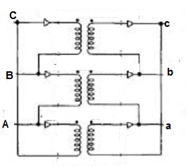
Fig. 8: Δ-Δ connection
Wye / Delta or Y/Δ connections:
- It is mainly used at the subtraction where the voltage is to be stopped down.
- Primary winding is Y connected and the ratio of secondary & primary line voltage is 1/
 .
. - There is 30˚Ø-shift between primary & secondary of line voltage.
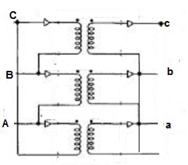
Fig. 9: Y/Δ connection
Delta/Wye or Δ/Y connection:
- It is used where we need to stop up the voltage.
- The primary and secondary line voltages and line currents are out of phase with each other by 30˚.
- The ratio of secondary to primary voltage is
 times of the transformation ratio of each transformer.
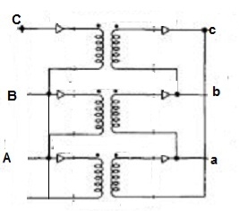
Fig. 10: Δ-Y connection
Key takeaway
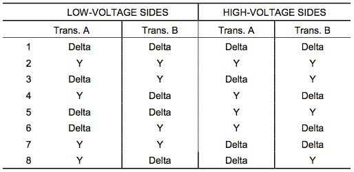
Que 1. A 3-Ø, 50Hz transformer has delta connected primary and star-connected secondary, the line voltage being 20,000 V and 500 V respectively. The secondary has a star connected balanced load at 0.8 lagging p.f. The line current of primary side is 5A. Determine the current in each coil of the primary and secondary line. Also find the output of the transformer?
→ Phase voltage on primary side = 20,000 V
Phase voltage on secondary =  V
V
K = 
Primary phase current = 
Secondary phase current = 
= 
= 200 A
Output =  VLILcosØ
= 
= 138.56 kW
Que 2. A 100 kVA, 3Ø, 50 Hz, 3500/500 V transformer is Δ – connected on the h. V side and Y-connected on the L.V. Side. The resistance of h.V. Winding is 3.5 Ω / phase and that of L.V is 0.02 Ω per phase. Calculate the iron losses of the transformer at normal voltage and frequency if its full load efficiently be 95.1 % at 0.8 p.f.?
→ Full load output = 100 × 0.8 = 80 kW
Input =  kW
kW
Total loss = Input – Output
= 83.2 – 80
= 3200 kW
K = 
K = 
= 
RO2 = R2 + k2R1
= 
= 0.044 Ωs
Full-load secondary phase current I2
= 
= 115.4 A
Total Cu Loss = 3I22RO2
= 3 × 0.044 × (115.4)2
= 1760 W
Iron Loss = Total loss – Cu Loss
= 3200 – 1760
= 1440 W
- The vector for the high voltage winding is taken as the reference vector. Displacement of the vectors of other windings from the reference vector, with anticlockwise rotation, is represented by the use of clock hour figure.
- IS: 2026 (Part 1V)-1977 gives 26 sets of connections star-star, star-delta, and star zigzag, delta-delta, delta star, delta-zigzag, zigzag star, zigzag-delta. Displacement of the low voltage winding vector varies from zero to -330° in steps of -30°, depending on the method of connections.
- Hardly any power system adopts such a large variety of connections. Some of the commonly used connections with phase displacement of 0, -300, -180″ and -330° (clock-hour setting 0, 1, 6 and 11).
- Symbol for the high voltage winding comes first, followed by the symbols of windings in diminishing sequence of voltage. For example, a 220/66/11 kV Transformer connected star, star and delta and vectors of 66 and 11 kV windings having phase displacement of 0° and -330° with the reference (220 kV) vector will be represented As Yy0 – Yd11.
- The digits (0, 1, 11 etc) relate to the phase displacement between the HV and LV windings using a clock face notation. The phasor representing the HV winding is taken as reference and set at 12 o’clock. Phase rotation is always anti-clockwise. (International adopted).
- Use the hour indicator as the indicating phase displacement angle. Because there are 12 hours on a clock, and a circle consists out of 360°, each hour represents 30°.Thus 1 = 30°, 2 = 60°, 3 = 90°, 6 = 180° and 12 = 0° or 360°.
- The minute hand is set on 12 o’clock and replaces the line to neutral voltage (sometimes imaginary) of the HV winding. This position is always the reference point.
- Example:
- Digit 0 =0° that the LV phasor is in phase with the HV phasor
Digit 1 =30° lagging (LV lags HV with 30°) because rotation is anti-clockwise. - Digit 11 = 330° lagging or 30° leading (LV leads HV with 30°)
- Digit 5 = 150° lagging (LV lags HV with 150°)
- Digit 6 = 180° lagging (LV lags HV with 180°)
- When transformers are operated in parallel it is important that any phase shift is the same through each. Paralleling typically occurs when transformers are located at one site and connected to a common bus bar (banked) or located at different sites with the secondary terminals connected via distribution or transmission circuits consisting of cables and overhead lines.
Phase Shift (Deg) | Connection | ||
0 | Yy0 | Dd0 | Dz0 |
30 lag | Yd1 | Dy1 | Yz1 |
60 lag |
| Dd2 | Dz2 |
120 lag |
| Dd4 | Dz4 |
150 lag | Yd5 | Dy5 | Yz5 |
180 lag | Yy6 | Dd6 | Dz6 |
150 lead | Yd7 | Dy7 | Yz7 |
120 lead |
| Dd8 | Dz8 |
60 lead |
| Dd10 | Dz10 |
30 lead | Yd11 | Dy11 | Yz11 |
- The phase-bushings on a three-phase transformer are marked either ABC, UVW or 123 (HV-side capital, LV-side small letters). Two winding, three phase transformers can be divided into four main categories
Group | O’clock | TC |
Group I | 0 o’clock, 0° | Delta/delta, star/star |
Group II | 6 o’clock, 180° | Delta/delta, star/star |
Group III | 1 o’clock, -30° | Star/delta, delta/star |
Group IV | 11 o’clock, +30° | Star/delta, delta/star |
Minus indicates LV lagging HV, plus indicates LV leading HV | ||
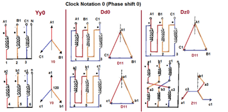
Fig. 11: Clock Notation: 0
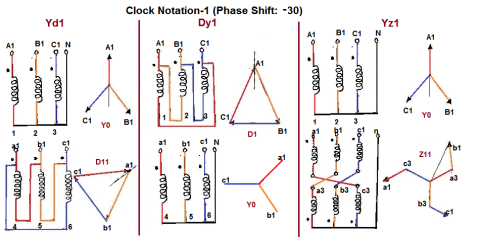
Fig. 12: Clock Notation: 1
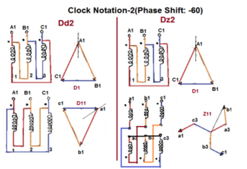
Fig. 13: Clock Notation: 2
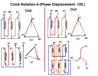
Fig. 14: Clock Notation: 4
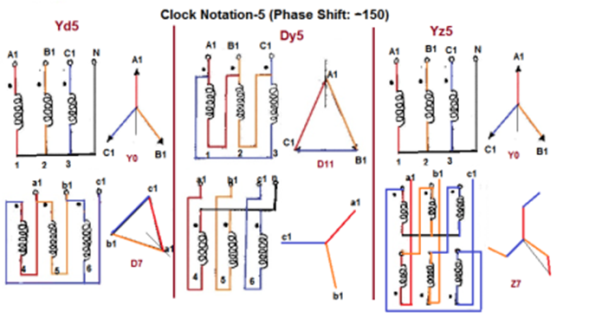
Fig. 15: Clock Notation: 5
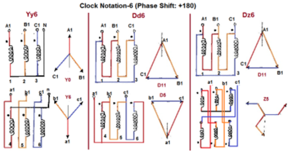
Fig. 16: Clock Notation: 6
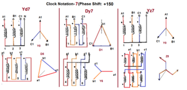
Fig. 17: Clock Notation: 7
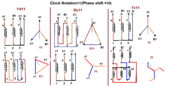
Fig. 18: Clock Notation: 11
Key takeaway
Vector Groups are the IEC method of categorizing the primary and secondary winding configurations of 3-phase transformers. Windings can be connected as delta, star, or interconnected-star (zigzag). Winding polarity is also important, since reversing the connections across a set of windings affects the phase-shift between primary and secondary.
The conditions are same as in case of 1-Ø transformer.
- The voltage ratio must refer to the terminal voltage of primary and secondary.
- The phase displacement between primary and secondary voltages must be same for all transformers.
- The phase sequence must be same.
- All three transformers in 3-Ø transformer bank will be of same construction.
For making 3-Ø to 3-Ø transformation from two transformers we use this connection.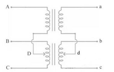
Fig. 22: Scott Connection
- The above figure shows that the centres of one transformer are tap, and has 0.866 tap and is known as Leaser Transformer.
- One ends of both the primary and secondary of Leaser transformer are joined to centre tap on both primary and secondary of main transformer.
- There is one transformer having its centre taps on both primary and secondary and is known as main transformer.
The voltage diagram is shown below
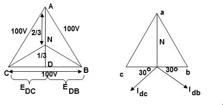
Fig. 23: Voltage and Phase diagram
- EDC and EDB are each 50 V and 180˚ out of phase because coils DB & DC are on same circuit but in opposition.
- EDA is equal to 86.6 V
 and lags behind the voltage across main by 90˚.
 - Idb lags behind voltage Edb by 30˚ and Idc leads Edc by 30˚.
- The teaser transformer and each half of the main transformer all operate at different power factors.
- Full rating of transformer is not utilized. The teaser transformer operate at 0.866 of its rated value and main transformer coil operates at cos 30˚ = 0.866 p.f
Key takeaway
- Used in an electric furnace installation where it is needed to operate two single-phase feeds and draw a balanced load from the three-phase supply.
- Used to supply the single-phase loads such as traction power. This helps to keep the load on the three-phase system as nearly balanced as possible.
- Used to link a 3-phase system with a two–phase system with the flow of power in either direction.
Que 1. What should be the kVA rating of each transformer in V-V bank when 3-Ø balanced load is 50 kVA. If a third transformer is connected for operation find % increase in rating?
→ kVA for each transformer has to be 15%
KVA per transformer = 
= 28.75
Δ-Δ bank rating = 28.75 × 3
= 86.75
Increase = 
= 72.5 %
Que 2. A balanced 3-Ø load of 120 kW at 1100V 0.866 lag p.f is supplied from 1500V, 3-Ø main through 1-Ø transformer connected – (i) Δ-Δ (ii) Y-Y
Find current in the windings of each transformer and p.F at which they operate in each case.
→ (i) Δ-Δ
 VLILcosØ = 120,000
 × 1100 × IL × 0.866 = 120,000
IL = 72.73 A
Secondary line current = 72.73 (= IL)
Secondary phase current =  = 41.99 A
K = 
Primary phase current =  = 20.99 A
(ii) Y-Y connection
 × 1100 × I × 0.866 = 120,000
I = 72.73 A
Secondary phase current = 72.73 A
Primary phase current =  = 41.99 A
Transformer p.f = 86.6 % of 0.866
= 0.75 (lag)
Que 3. Two transformers are required for a Scott connection operating from 410 V 3-Ø supply for supplying two 1-Ø furnaces at 200 V on the two-phase side. If total output is 130 kVA, calculate secondary to primary turn ratio and the winding of each transformer?
→ For main Transformer
Primary voltage = 410 V
Secondary voltage = 200 V

Secondary current =  = 325 A
Primary current = 325 × 
= 153.54 A
For teaser Transformer
Primary volts =  = 355 V
Secondary volts = 200 V

If only two transformers are used and 3-Ø supply is connected to the primaries as shown below in figure, then three equal 3-Ø voltage will be available at the secondary terminal on no-load.
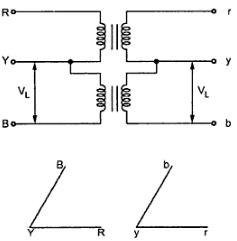
Fig. 19: V-V connection
As one transformer is removed, then the total load carried by V-V bank is not 2/3 of the capacity of Δ-Δ bank but only 57.7% of it. The reduction is of 15% from normal rating.
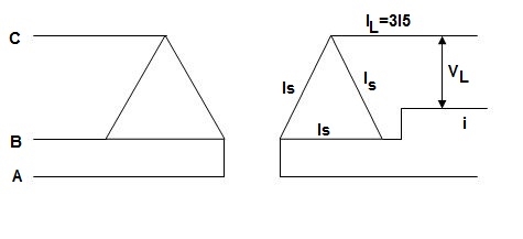
Fig. 20: Closed Δ
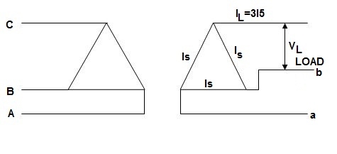
Fig. 21: Open Δ
Now from above figure we can mathematically prove that the capacity is 1/ for this connection.
For closed Δ:
Δ-Δ capacity =  VLIL =
  VL(
VL( IS)
IS)
= 3VLIS
For open Δ:-
V-V capacity =  VLIL =
  VLIS
VLIS

= 
Uses: -
1) When three phase loads are too small for the installation of full 3-Ø transformer.
2) When any one of the transformers in Δ-Δ is disabled.
3) When it is found that in near future can increases the change of closing of open delta.
Disadvantage: -
1) The average p.f at which the V-bank operate is less than that of the load.
2) If the load is balanced than also the secondary terminal voltage lend to become unbalanced.
Power supplied by V-V Bank
For V-V connection one transformer operates at p.f cos(30 - Ø) and other at cos(30 + Ø), which means they both does not have same voltage regulation.
P1 = kVA cos(30 - Ø)
P2 = kVA cos(30 + Ø)
1) When Ø = 0˚
Each transformer has p.f = 0.866
2) When Ø = 30˚
One transformer has p.f = 1, other has p.f = 0.866
3) When Ø = 60˚’
In this case only one will supply the entire load as, one has p.f = 0.866 and other has p.f = 0
Key takeaway
1) When three phase loads are too small for the installation of full 3-Ø transformer.
2) When any one of the transformers in Δ-Δ is disabled.
3) When it is found that in near future can increases the change of closing of open delta.
As the name suggests this transformer can be made by adding one additional winding. The main use of this type of transformer is for interconnections with the transmission line at various voltages, for measuring voltages of an H.V side transformer, synchronous condensers can be connected to this winding to inject reactive power in system for voltage control. Below is shown the figure which explains how the tertiary winding can be used for stabilization.

Fig. 24: Tertiary winding for stabilization
The unbalanced load cab be divided into three phase sets i.e. positive, negative and zero sequence component. The star-star connection unbalanced load provides high reactance between line and neutral. The zero-sequence current component on secondary side cannot be balanced by primary current and hence magnetic flux is developed on the secondary side. Then the delta connected tertiary allows the circulation of zero-sequence current in it, as shown in the above figure. The equivalent circuit of the three winding transformer is shown below. There are three terminals primary (1), secondary (2), and tertiary (3) and one common terminal, neglecting the exciting current.
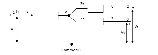
Fig. 25: Single phase equivalent circuit of three winding transformer
The impedance can be calculated by the short circuit test. If  is the short circuit impedance of winding 1 and 2 with winding 3 open, then we can write
 =
=  +
+


The above three equations can also be written as


The core loss, magnetizing loss and turn ratio can be determined by open circuit test on any one of the three windings.
Key takeaway
The main use of this type of transformer is for interconnections with the transmission line at various voltages, for measuring voltages of an H.V side transformer, synchronous condensers can be connected to this winding to inject reactive power in system for voltage control.
References
- [R1] A.E. Clayton and N. N. Hancock, “Performance and Design of Direct Current
- Machines”, CBS Publishers, Third Edition.
- [R2] A.E. Fitzgerald, Charles Kingsley, Stephen D. Umans, “Electrical Machines”, Tata McGraw Hill Publication Ltd., Fifth Edition.
- [R3] A.S. Langsdorf, “Theory and performance of DC machines”, Tata McGraw Hill.
- [R4] M.G. Say, “Performance and Design of AC. Machines”, CBS Publishers and Distributors.
- [R5] Smarajit Ghosh, “Electrical Machines”, Pearson Education, New Delhi.
- [R6] Charles I Hubert, “Electrical Machines Theory, Application, & Control”, Pearson Education, New Delhi, Second Edition.