Unit-2
Network Theorem
This theorem states that in a linear network containing several independent sources, the overall response at any point in the network equals the sum of responses due to each independent source considered separately with all other independent sources made inoperative.
Question 1. Find the current through  resistance.

Fig 1 Circuit Diagram
Solution:
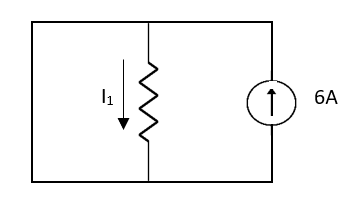
Fig 2 Short circuit 2V
 1 = 0
1 = 0
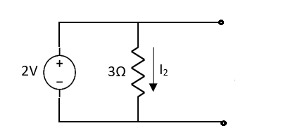
Fig 3 Open circuit 6A
 2 =
2 =
 1 +
1 +  2
2 
Key takeaway
Special Case
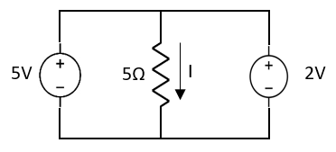
Fig 4 Circuit with two voltage source
Since two voltage sources with different magnitudes in parallel cannot be connected as in a single branch, two different currents are not possible (if 5V then I = zero).
Question 2: Find Value of current I
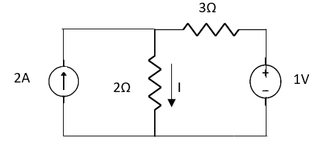
Fig 4 Circuit Diagram
Sol: Applying Superposition Theorem
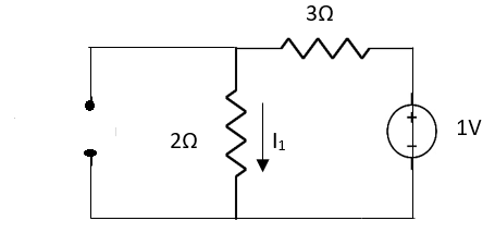
Fig 5 Circuit with 2A open circuit
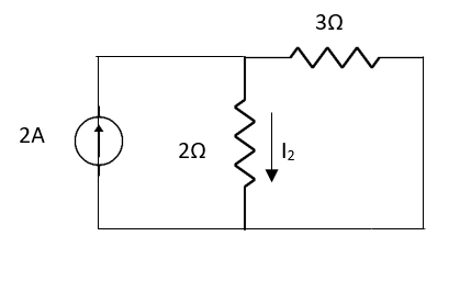
Fig 6 Circuit with 1V short circuit
 1 =
1 = 
 2 =
2 = 
=
 1 +
1 +  2
2
= 
THEVENIN’S AND NORTON’S THEOREM
Thevenin’s Theorem states that a two-terminal network containing sources and passive elements is equivalent to a voltage source in series with the network impedance with all independent sources removed.

Fig 7 Two-port network

Fig 8 Thevenin’s equivalent of A
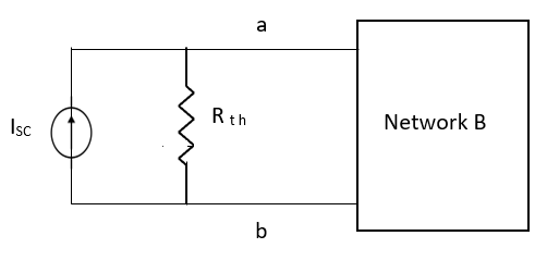
Fig 9 Norton’s equivalent of A
Norton’s Theorem states that a two-terminal network containing sources and passive elements is equivalent to an independent current source in parallel with the network impedance with all independent sources removed. The current of the current source has the same magnitude and reference direction as that of the current which would exist at the terminal in the original network if the terminals were short-circuited.
The short circuit current is then given as
 sc = Vth/Rth
CONDITIONS FOR APPLICATION
Firstly, open circuit terminal A and B.
2. If network A is operating with independent and dependent sources:
3. If the network is operating with only dependent sources:
Connect generation between A and B

First, open circuit terminal A and B.
Find out the voltage between A and B this is Vth
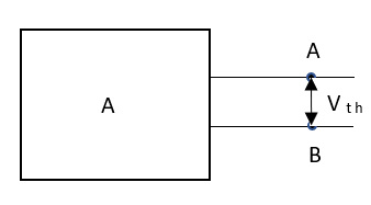
Fig 10 Terminal where we find Vth


Fig 11 Finding Isc
Key takeaway
For finding Rth we SC all voltage sources and OC all current sources.
For finding Isc Remove network B and S.C. the terminal A and B and current from terminal A to B Isc.
Question: Find Vth and Rth for the circuit shown below?
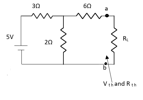
Fig 12 Circuit Diagram
Answer:
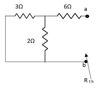
Fig 13 Circuit for finding Rth


Fig 14 Finding Vth across a and b


Finding Isc from circuit directly:
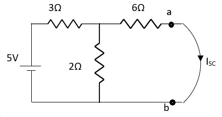
Fig 15 Finding Isc
By KCL,


Question: Find Vth and Rth across a and b?
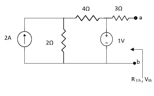
Fig 16 Circuit Diagram
Sol: Finding Rth
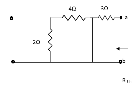
Fig 17 Circuit for Rth
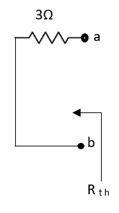
Also, clear from a circuit that Vth = 1V.

Fig 18 Circuit for Isc
By applying KVL we get,
1-3Isc=0
Isc= A
A
Que: Find Isc and Rth across terminal a and b?
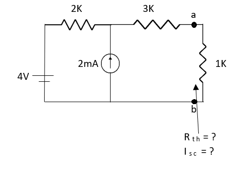
Fig 19 Circuit Diagram
Ans;

Fig 20 Circuit for finding RTh
Rth=3k+2k=5k
By applying KVL we get


Therefore, 
Question: Find the value of voltage Vx?
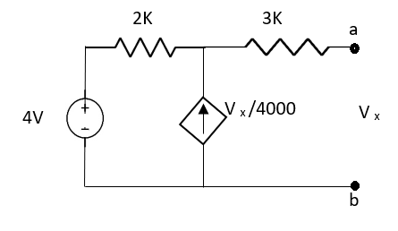
Fig 21 Circuit Diagram
Solution: For Rth
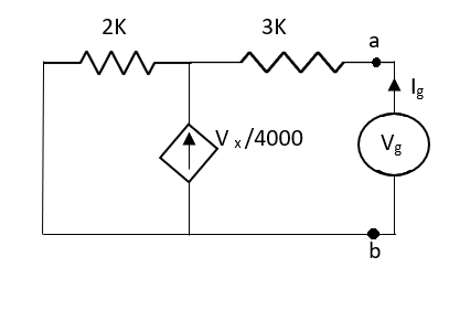
Fig 22 Circuit for finding Rth
By KCL,


But, 


By KVL,


Question: Find the value of current I in the circuit?
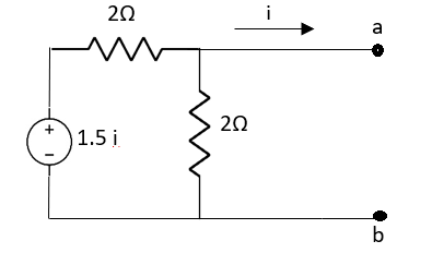
Fig 23 Circuit diagram
Solution: Since, no independent source is present so,
Isc = 0
And we know that,


Since Rth cannot be zero

Fig 24 Circuit for finding Rth


But 


Question: Find out Norton’s equivalent
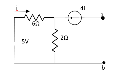
Fig 25 Circuit diagram
Solution:

Fig 26 Circuit for finding Isc
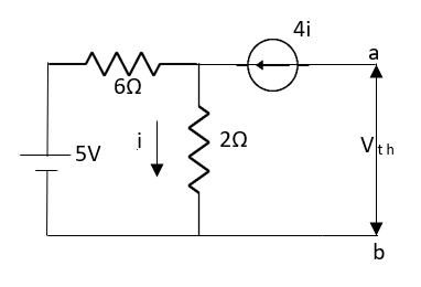
Fig 27 Circuit for finding Vth

Since there is no significance of the current source


 A
A
MAXIMUM POWER TRANSFER THEOREM
The maximum power transfer theorem states that to obtain maximum external power from a source with a finite internal resistance, the resistance of the load must equal the resistance of the source as viewed from its output terminals.
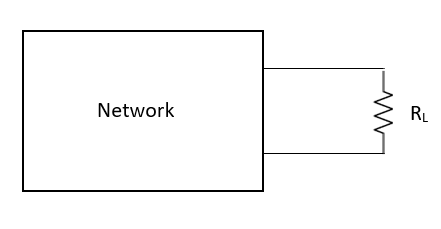
Fig 28 Network With load RL

where Rth is Thevenin’s equivalent resistance across a and b.
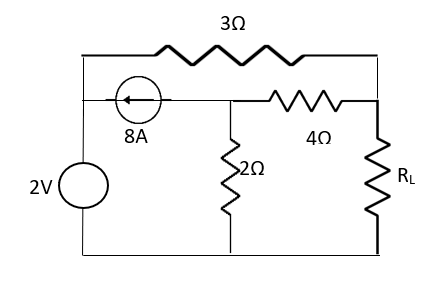
Fig 29 Circuit Diagram
Maximum power is absorbed by ZL when
Condition: 


Comparing real and imaginary parts


OR


Maximum power absorbed by ZL is


Key takeaway
For maximum power transfer 
Question: Find out the value of load resistance if power absorbed is maximum.
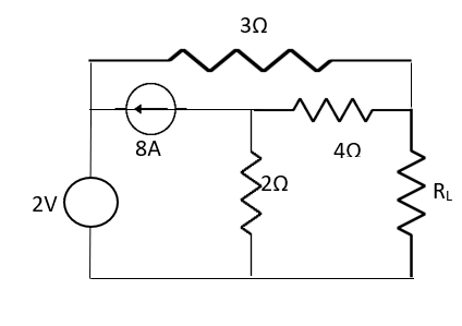
Fig 29 Circuit DIagram
Solution: find Thevenin’s equation

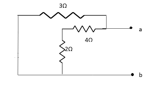
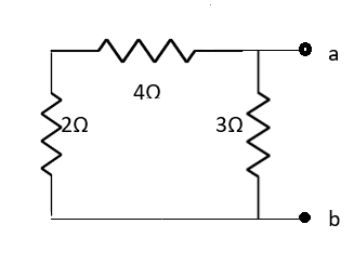
Fig 30 Finding Rth


Question: Find maximum power delivered is RL if its value is
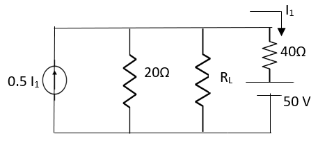

Solution

Fig 31 Circuit for finding Rth


Therefore, 
RECIPROCITY THEOREM
In a voltage source V (current source i) located at one point in a network produces current i (voltage v) at the second point in the network then the same voltage source V (current source) acting at the second point if produces the same current i at the first point the network is called as Reciprocal Theorem.
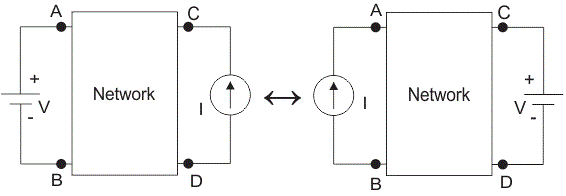
Fig 32 Network from which reciprocity is described
When the excitation is a voltage and response is current then short circuit conditions are implied at both ends. In this theorem, we can also apply the current source at one end and measure the open-circuit voltage at the other end, and open circuit conditions are implied at both ends. The assumptions for the theorem to apply to the network are
i) All initials conditions are zero.
ii) There is only one source of excitation in the network.
iii) The network is linear.
iv) The dependent sources are excluded in the network even if they are linear.
Q) Verify the Reciprocity theorem for the given network?
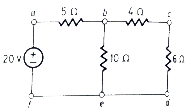
Fig 33 Circuit DIagram
Sol: The value of current Ix flowing due to 20V source is
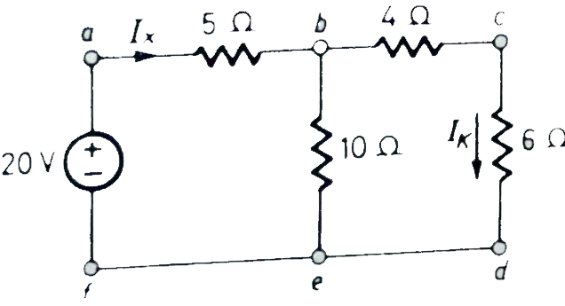
Fig 33 When 20V is at its place
Ix =  = 2A
= 2A
By current Division
Ik = Ix = 1A
= 1A
Now the voltage source of 20V is connected to branch cd. The current source now will be given as
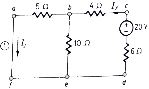
Fig 34 When 20V is connected to the cd
Iy=  = 3/2 A
Then Ij = Iy  = 1A
= 1A
From above we see that Ik = Ij = 1A
The reciprocity theorem is verified.
Milliman’s Theorem:
This theorem states that if n voltage sources having emfs E1, E2,……En and internal impedance Z1, Z2,…. Zn is connected in parallel as shown below. Then these voltage sources may be replaced by a single voltage source E in series with an impedance Z.
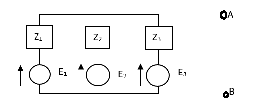
Fig 35 Millman Theorem Circuit
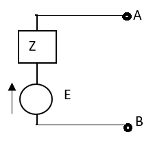
Fig 36 Equivalent Circuit for Millman Theorem


Dual of Milliman’s Theorem:-
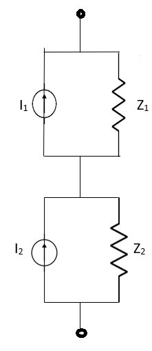
The equivalent circuit is shown below
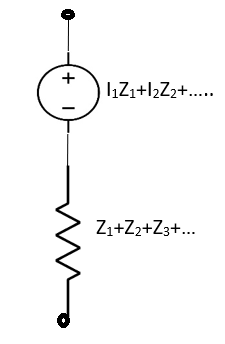
Fig 37 Equivalent circuit for Dual of Millman's Theorem
Key takeaway
The equivalent expression for Millman's theorem is given by 
Question: Calculate current I through the 2Ω resistor shown below using Milliman’s Theorem.
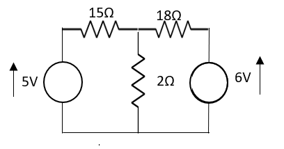
Solution: From Milliman’s Theorem, the equivalent circuit is
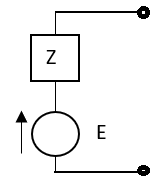
 ,
, 


The equivalent Milliman’s Network will now become as shown below
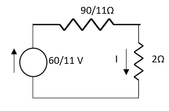
Fig 38 Mill man Equivalent Network
So, current I through 2Ω will be


Node: Node is a point joining two or more than two elements
n = no of nodes

Fig 39 Circuit with nodes
Branch: Element with nodes at both ends
b = total no of branches
b = 7
Graph: If all the elements (R, L, C) of any electrical Circuit are replaced by a line then it becomes a graph
Voltage source will be short-circuited and amount source will be open circuit
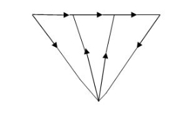
Fig 40 Graph of the above circuit
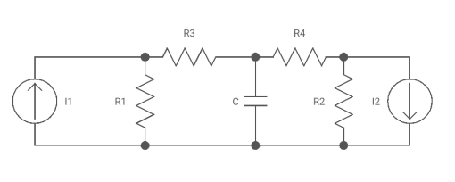
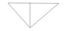
Fig 41 Graph for the above circuit
Tree: It includes all nodes of the graph and (n-1) branches without making any closed path
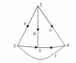
Fig 42 Graph of a circuit
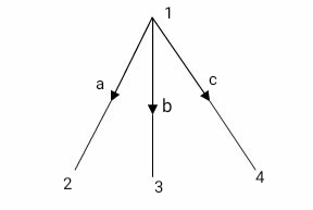
Fig 43 Tree of the above graph
Twig: Branches of free are called twigs. It is no. of nodes of a graph then no. of twigs are n-1
For any electrical at no. of twigs are equal to no. of possible nodal equations.
Cotree: Remaining part of free. Shown by dotted lines.
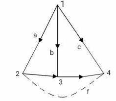
Fig 44 C-tree of the above graph
Links or chords: Branches of cotree are called links or chords. If n is no. of nodes and b is no. of branches of the graph then no. of links or chords denoted by L.
L = b – n + 1
For any electrical circuit, no. of loop equations are equal to no. of twigs
Que. Find the total possible no. of trees?
T = n (n-2)
n = no. of nodes
T = 6 (6-2) = 6 4
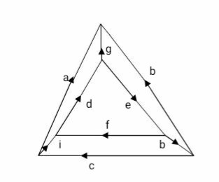
The orientation of f- cut set as same as the direction of current in twig associated with cut – set
It gives information about branch voltage
Tie – set: It is a collection of branches that includes only one link and some twigs
f- tie set: It is a mathematical representation of the f-tie set in form of a matrix with all the branches of the graph as columns and all the T-Set (loop) as rows.
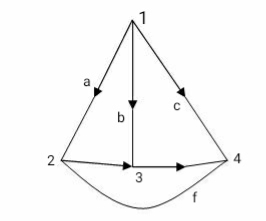
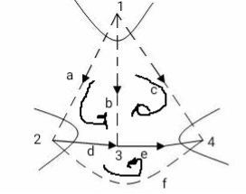
Fig 45 Cut set for the above graph
The orientation of T-Set is the same as the direction of current in the link associated with T-Set
Incidence Matrix
Mathematical representation of the graph in form of a matrix that includes all the branches as columns and all the nodes as rows.
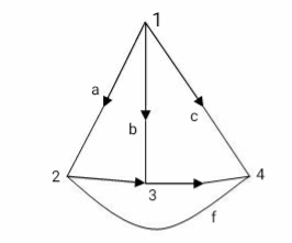
Fig 46 Graph
The Sum of all the elements for any column of the incidence matrix is zero.
Reduced Incidence Matrix:
If we remove any one of the rows from the incidence matrix then it becomes reduced incidence matrix is (n-1) X b
Cut set: Collection of branches that includes only one twig and number of links.
Fundamental Cut set / f- cut set :-
It is a collection of branches that includes one and only one twig and a minimum number of links.
f- cut set matrix:-
It is a mathematical representation of the f-cut set in form of a matrix with branches of the graph as a column and cut set as rows.
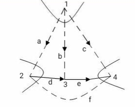
Fig 47 Fundamental cut set
Va Vb Vc Va Ve Vf
a b c d e f
C1 (Vb) 1 1 1 0 0 0
C2(Vd) -1 0 0 1 0 -1
C3(Ve) 0 0 1 0 1 -1
Vb-Vd Vb Vb+Ve Vd Ve -Vd-Ve
Key takeaway
L = b – n + 1
Reference
[1] Network Analysis Third Edition by M. E. Van Valkenburg, Prentice Hall of India Private Limited.
[2] Network Analysis & Synthesis by G. K. Mittal, Khanna Publication.
[3] Network Analysis and Synthesis by Ravish R Singh, McGraw Hill.
[4] Introduction to Electric Circuits by Alexander & Sadiku, McGraw Hill.
[5] Introduction to Electric Circuits by S. Charkarboorty, Dhanpat Rai & Co.
[6] Fundamentals of Electrical Networks by B.R.Gupta & Vandana Singhal- S.Chand Publications
[7] Electrical Circuit Analysis 2nd Edition by P. Ramesh babu, Scitech Publication
India Pvt Ltd.