Unit-3
Transients in RLC circuit
3.1.1 Solutions of differential equations
General and Particular Solution
A linear differential equation that describes any circuit has two parts in its solution, one is a complementary function and the other is a particular solution. The complementary solution gives the transient response and the particular solution deals with a steady-state response. The complete or total response of the network is the sum of the transient response and steady-state response which is represented by the general solution of the differential equation.
First-order homogenous differential equation.
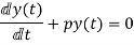
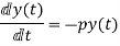
Integrating both sides
y(t)=k
First-order non-homogenous differential equation
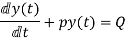
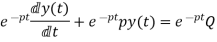
Integrating the above equation we get
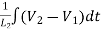
y(t) =∫ Q
=∫ Q 
y(t)= ∫ Q
∫ Q 
The first term of the above solution is known as particular Integral and the second is known as a complementary function.
FOR RL Circuit
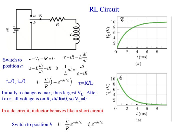
Fig1: Series RL circuit
After the switch is closed applying KVL
 =0
=0
This is a first-order homogeneous differential equation so
 dt
dt
Integrating both sides
ln i=  t+K
t+K
taking the antilog of both sides
i=k
At t=0
i(0)= =I0
=I0
 =ke0
=ke0
The particular solution is given as
i=  for t≥0
= for t<0
FOR RC Circuit
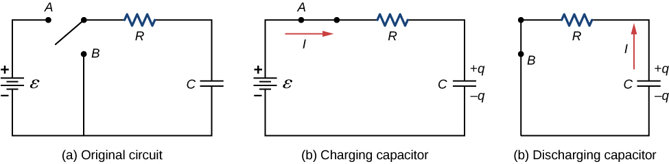
Fig 2: Series RC circuit
 =V
=V
For t>0 applying KVL
Ri(t)+ +V=0
+V=0

Hence the general solution of the above equation is calculated the same as for the RL circuit
i=k
i(0)=- 
Hence, a particular solution for the network is given as
i=-  tfor t≥0
= for t<0
Time Constant
The time constant for the RL circuit
From the above section for RL circuit at t≥0
i= 
i=I0
I0=
Time taken for current to drop from unity to zero is called the time constant T.

 sec
sec
FOR RC Circuit
It can be calculated in the same manner as for series RL circuit
The time constant is given as 
T=RC
Key takeaway
y(t)= ∫ Q
∫ Q 
The first term of the above solution is known as particular Integral and the second is known as a complementary function.
For RL circuit Time constant  sec
sec
For RC circuit Time constant  = RC sec
3.1.2 Network equations using the classical method for R-L, R-C, and R-L-C circuits
The network equations can be written for knowing the current or voltage of any branch or element in the given circuit. The equations can be voltage equations or current equation for the circuit given.
The voltage equations are written as
Fig 3 Circuit for loop analysis
For Loop 1 with il

For Loop 2 with i2

For Loop 3 with i3

The current equations are written as
For these, we assume every node as a voltage point and write the current equation for every element. For the current source, the current entering is negative.
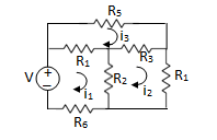
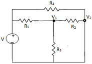
Fig 4 Circuit for Node analysis
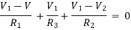
For node V1
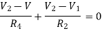
For node V2
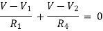
For V
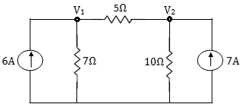
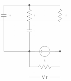
Example: Using nodal analysis find the voltage across 5resistor.
Solution:
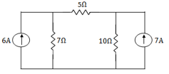
For V1
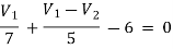
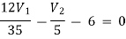
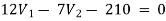 1
1
For V2
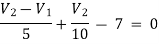
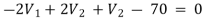
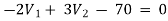 2
2
Solving 1 and 2:

For 5 voltage = 
= -50.9 + 57.27
= 6.37V
Que Write the loop equations for the given circuit below?
Solution:
For loop 1
For loop 2
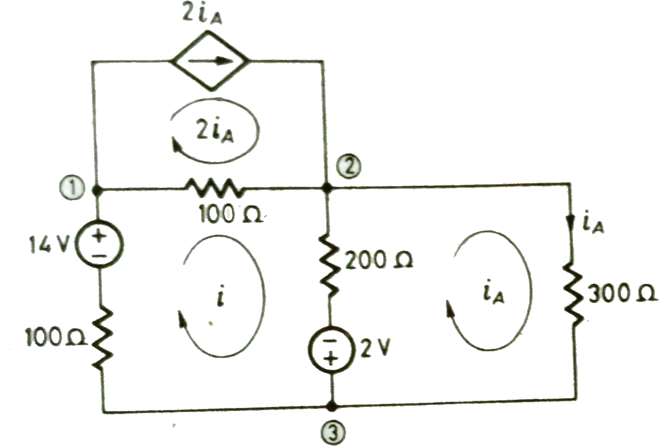
Q) Use mesh equations to find iA for the circuit given below?
Sol: For loop with current I the equations will be
100i+100(i-2iA)+200(i-iA)-2-14=0
400i-400 iA=16……….(1)
Equation for loop with current iA
2+200(iA-i)+300 iA = 0
-200i+500 iA= -2………(2)
Solving above equations we get
i=60mA
iA = 20mA
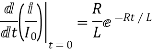
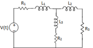
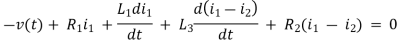
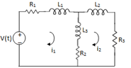
Q) Write the integro-differential equation for the loop currents shown below.
Sol: Equation for loop 1 with current i1
v(t)=(R1+R2+R4)i1 +L -R2 i2+ R5i3
The equation for loop 2 with current i2
-R2i1+(R2+R3) i2 + +R3i3 = 0
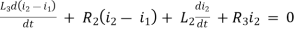
Equation for loop 3 with current i3
V(t) = R1i3+R3i3+(R1+R3+R5) i3+
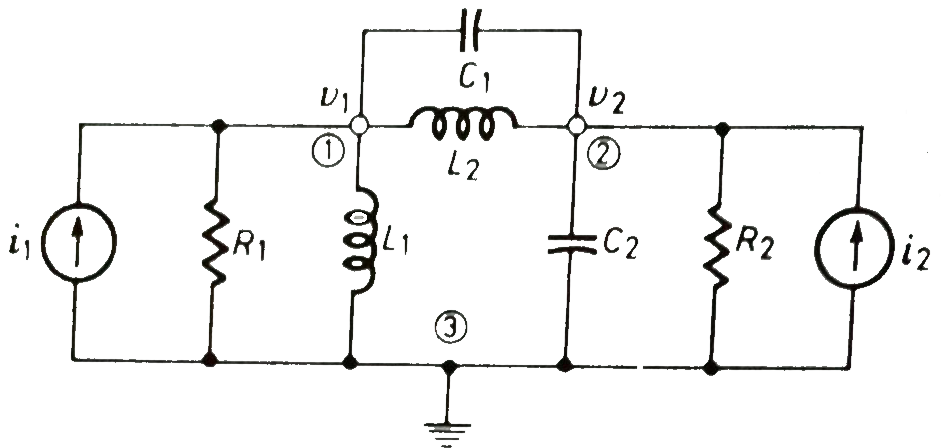
Q) For the given network write the integrodifferential equation?
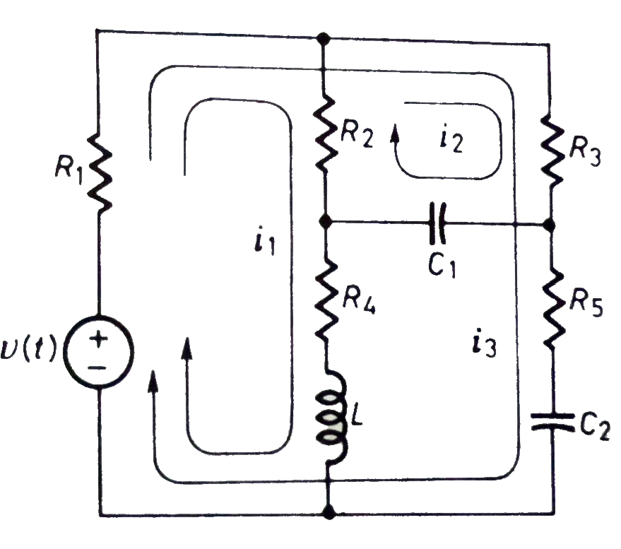
Sol: Let V1 and V2 be the node voltages.
The equation for node v1 will be
 +
+ +
+ +C1
+C1 = i1
= i1
 + C2
+ C2 + C1
+ C1 +
+ = i2
= i2
INTIAL CONDIONS:
For R:
Time t=0- , time t=0-1 time t= infinity
 Fig 5 Behaviour of R for t=0-, t=0+ and t= infinity
# In the case of the capacitor:-
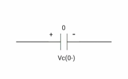
At time t= 0-
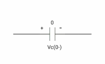
:. The capacitor is initially uncharged
Q (0-) =0
Q=cv
Q(0-) = cvc (0-)
Vc (0-) =0
At time t= 0+
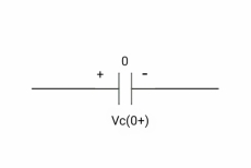
By low of conservation of charges
Q(0-) = Q(0+)
Cvc(0-) =cvc(0+)
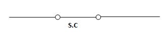
Vc (0+) =0
Hence acts as

Fig 6 Capacitor when charged for t=infinity acts as SC
If the capacitor is initially uncharged at t= 0- then the voltage across the capacitor is zero at t=0+ capacitor will follow low of conservation of charges and Vc(0+) =0 it means at t=0+ capacitor behaves as a short circuit, in other words, the voltage across the capacitor cannot change instantaneously.
At time t= infinity,
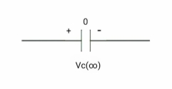
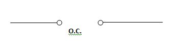
Fig 7 Capacitor fully charged behaves as OC
i = cdvc/dt constant and maximum
hence , i= 0
At t= infinity, the capacitor will be fully charged or voltage across the capacitor is constant and current through the capacitor is zero so, the capacitor will behave as open –circuit
Say capacitor is initially charged
Q(0-) = Q(0+)
Cvc(0-) =cvc(0+)
V1 = Vc (0+)
at time t= 0-,

at time t= 0+,

at time t= 0+
It capacitor is initially charged at t= 0- as voltage across capacitor is V1 than at t=0+ inductor behaves as a voltage as a voltage source with value V1
At t=infinity

Fig 8 Capacitor fully charged behaves as OC
If the capacitor is initially charged and it is connected to any independent source for a long time than the current through the capacitor is zero and the capacitor will be fully charged and it behaves as o.c
For L
At t=0- the inductor is initially unenergized

Φ(0-) = 0
Φ = Li
Φ(0-) =L i(0-)
i(0-) = 0
At t=0+
By law of conservation of flux
Φ(0-) = Φ(0+)
L i(0-) = L i(0+)
i(0+) = 0
Hence acts as

If the inductor is initially unenergized or the initial flux is zero then the initial current through the inductor is also zero at t=0-. At t=0+ inductor will follow the law of conservation of flux and current through inductor at t=0+comes out to be zero which means that current through inductor changes instantaneously at t=0+ and it behaves as OC.
At time t = infinity
VL= Ldi/dt
VL= 0
At t= inductor will be fully charged or current through the inductor is maximum and constant and the voltage across the inductor is zero or inductor behaves as S.C.
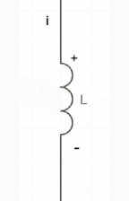
If initially energized or has some flux or some initial current
At time t= 0-
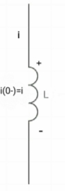
At t=0+
By law of conservation of flux
Ø= Li =0
Ø(0)= Li(0-)
i(0-)= i(0+)
i(0+) = i1
Hence acts as
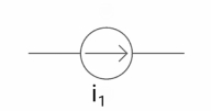
Fig 9 Behaviour of inductor for t= 
If the inductor is initially energized at t=0- then at t=0+ it behaves as a current source because the current through the inductor cannot change instantaneously.
At t=  inductor will be fully energized the current through it will be maximum and constant and the voltage across the inductor is zero and behaves as SC
Key takeaway
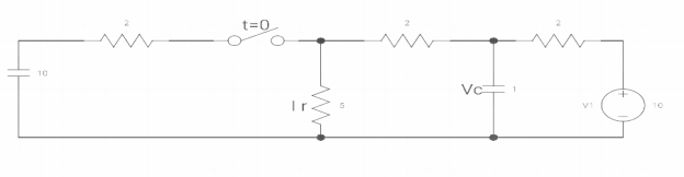
Q) In-network below switch is moved from 1 to 2 at t=0 a steady state is achieved already. Fond capacitor voltage Vc(t) and current i(t) through 200Ω?
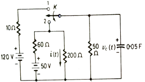
Fig 10 Circuit Diagram
Sol: The Voltage across the capacitor is given by
Vc(t)= K1+K2 
The steady-state is reached when t= the above equation becomes
Vc( )= Lt t-->
 K = K1
At t=0
Vc(0)= K1+K2
K2= Vc(0)- Vc( )
)
The final responsibility for the circuit is given as
Vc(t)= Vc( )-[Vc(
 )-Vc(
)-Vc( )]
)]
When the switch is at position 1
Vc(0)=  x 50 = 100V
So, voltage of capacitor at t=0 and t=0+ will remain same.
TO find Req we replace the voltage source with a short circuit
Req = 60||200||50 = 24 Ω
The time constant will be T = ReqC = 24x0.05 = 1.2sec
Switch at position 2
The steady-state voltage across the capacitor is given by
 =
=  +
+ 
Vc( ) = 20V
The complete response will be
Vc(t)= Vc( )-[Vc(
 )-Vc(
)-Vc( )]
)]
Vc(t)= 20 –[20-100]
Vc(t)= 20+ 80 
The value of current at switch position 1
I= 50/(200+60) = 0.192A
When switch is at 2
i(0+) = 100/200= 0.5A
i( ) = Vc(
 ) /200 = 0.1A
The complete response of current is
i(t)= i( )-[i(
)-[i( )-i(
)-i( )]
)]
i(t)= 0.1-[0.1-0.5]
i(t)=0.1+0.4
Ques Find the value of V0(t) for the circuit below?
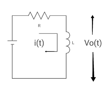
Sol:
Time constant, c= L/Req = L/R
V( ) = 0
) = 0
V(0) = VR
i( ) = VR/R
i(0) =0
By KVL,
VR=i(t) R + L di/dt(t)
On solving
V0(t)= VR e-tR/L
Ques Find iL(t) for the circuit below. For t>0?
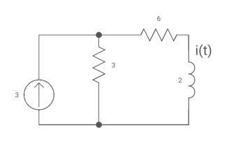
Sol: The circuit for Req will be
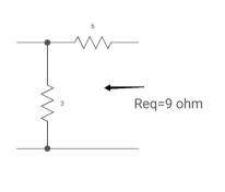
Fig 11 Circuit for Req
Req = 6+3
= 9ohm
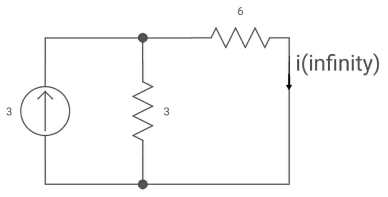
Fig 12 Circuit when inductor acts as short circuit
T= L/Req = 2/9 sec
i(0) =0
i( ) = 3*3/6+3 = 1A
i(t) = 1 [1-e4.5t]
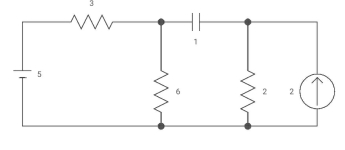
Ques Capacitor is initially uncharged find Vc (t); t >0
Sol:
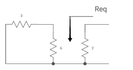
Fig 13 Circuit for Req
Req = (3116)+2
=2+2 = 4ohm
T= C Req= 2 sec
Clearly Vc(0) =0
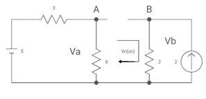
Fig 14 Circuit when the capacitor acts as an open circuit
By voltage divides, VA = 5*6/3+B = 30 v/9
Clearly by ohms low
VB = 2*2 = 4v
Apply KVL, VA-Vc-VB =0
Vc( ) = 30/9 – 4 = -2/3 V
Vc (t) = -2/3 [1- e0.25t]
CURVE:
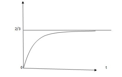
Vc(t) =2/3 [1-e-0.5t]
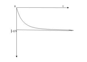
Fig 15 Response for the above circuit
Vc(t) = -2/3 [1-e-0.5t]
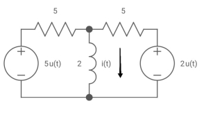
Ques Find i(t) for the given circuit below?
Sol: We know i(t) = i ( ) +[i(0)- i(
 )] e-t/T
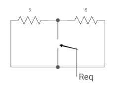
Fig 16 Circuit for Req
Req = 5*5/5+5 = 5/2 ohm
T=L/Req = 4/5 sec
Also
i(0) =0
i( ) = u(t) +2/5 u(t)
i(t) = 1.4 [1-e-5/4t)]u(t)
Ques: If switch ‘s’ closed for a long time before opening at t=0-. Find Vx (0+)?
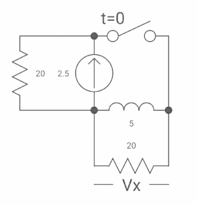
Fig 17 Circuit diagram
Sol: At t= 0- the switch was closed,
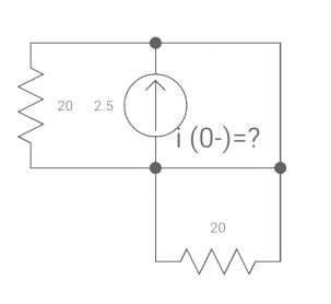
Fig 18 Switch is open
iL(0-) = 2.5A
At t= 0+
Inductor is initially charged so iL(0-) = iL(0+)
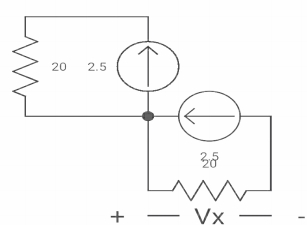
Fig 19 when switch is closed for long
-Vx = 20x2.5
Vx = -50A
Ques: Find VR(0+) and dil/dt(t) = 0+ If switch is opened at t= 0?
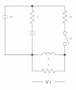
Sol: At time t=0-
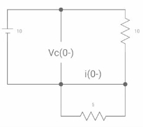
Fig 20 Capacitor SC switch closed for long
At t=0-
Vc(0-) = 10V
IL(0-) = 10/10 = 1 A
Also, iL(0-) = iL(0+) = 1A
VR(0+) = 5V
Ldi(t)/dt = VL (t)
diL(t)/dt = VL(t)/L
At t= 0+
d iL (0+) /dt = VL(0+)/L
-VL (0+)-VR =0
VL (0+) = -5V
diL(t)/dt at t=0+
VL(0+)/L =-5/2
dil/dt(o+) = 2.5 A/s
Ques: Find Vc(o+) and iR (o+) it switch ‘s’ is closed at t=0?
Soln:- At t=0-
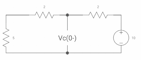
Fig 21 When switch opened at t=0
Sol As the capacitor is fully charged so acts as an open circuit
Vc (0-) = 7*10/7+2 = 70/9v
At t=0+
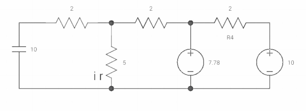
Fig 22 At t=0+ circuit
Vc(0+) = Vc (0) = 40/9v
By applying kcl at A,
VA-10/2+ VA/5+VA-7019/2 =0
VA [1/5+1/2+1/2] = 5+35/9
Va [6/5] = 80/9
Va= 400/54v
IR (0+) = Va/5 = 400/54*5 = 80/54 A
Q) Find diL(t)/dt and dVc(t)/dt at t=0+. If switch is opened at t=0?
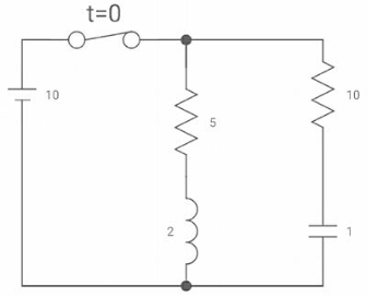
Sol: At t=0-
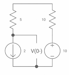
Fig 23 Switch closed for long
Vc(0-) =10V = Vc(0+)
iL(0-) = 2A
diL(t)/dt = VL(t)/L
At t=0+
diL(0+)/dt = VL(0+)/L
Similarly, C = ic(t)
 = ic(t)/C
At t=0+
 = ic(0+)/C
ic(0+) = -2A
Reference
[1] Network Analysis Third Edition by M. E. Van Valkenburg, Prentice Hall of India Private Limited.
[2] Network Analysis & Synthesis by G. K. Mittal, Khanna Publication.
[3] Network Analysis and Synthesis by Ravish R Singh, McGraw Hill.
[4] Introduction to Electric Circuits by Alexander & Sadiku, McGraw Hill.
[5] Introduction to Electric Circuits by S. Charkarboorty, Dhanpat Rai & Co.
[6] Fundamentals of Electrical Networks by B.R.Gupta & Vandana Singhal- S.Chand Publications
[7] Electrical Circuit Analysis 2nd Edition by P. Ramesh babu, Scitech Publication
India Pvt Ltd.


