Unit 2
Major Electrical Equipment's in Power Station & Underground Cables
The power station under study is made up of 65 solar panels over a surface area of 136 m2 with a storage reservoir of 4,000 litres. Each solar panel is made up of eight emerge sources the main ones of which are copper, glass and aluminium as well as the work element.
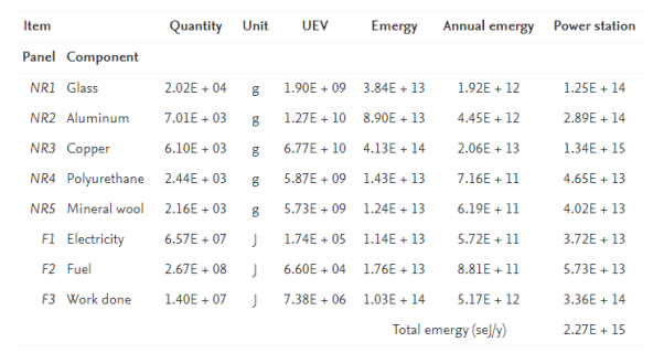
Special features
- It is an industrial facility for generation of electric power.
- Power stations are connected to electrical grid.
- Most of the power stations contain one or more generators , rotating machine to convert mechanical power into three phase electric power.
- The relative motion between magnetic field and conductor creates electric current.
Key Takeaways:
In a natural gas power station, simple cycle gas turbines inject compressed air into a combustion chamber, along with fuel, to produce a high pressure hot gas stream that is expanded in a turbine to produce electricity.
Alternators
- Each alternator is coupled to a steam turbine & converts mechanical energy of the turbine into electrical energy.
- The electrical output from the alternator is delivered to the bus bar through transformer.
- The alternators may be hydrogen or air cooled.
Transformers
A generating station has different types of transformers, are as follows:
- Main step-up transformer which are used for generation voltage for transmission of power.
- Station transformation which are used for general service in the power station.
- Auxiliary transformer which supply to individual unit auxiliaries.
Switchgear
Switchgear sense the abnormal conditions in the electrical network & isolate faulty part from the healthy section. It contains circuit-breakers, relays, switches & other control devices.
Exciter
- Exciter is a dc compound generator and mounted on the same shaft of the steam turbine and generator.
- It continuously supply the field winding of the alternator.
Necessity of exciters
Excitation system is required to provide the necessary field current to the rotor winding of a synchronous machine. Availability of excitation always important. Larger the load currents, lower the speed and lagging power factor which require more excitation.
Types
1. DC Excitation System
2. AC Excitation System
3. Static Excitation System Exciters
Key Takeaways:
The DC excitation system has two exciters – the main exciter and a pilot exciter. The exciter output is adjusted by an automatic voltage regulator (AVR) for controlling the output terminal voltage of the alternator.
DC excitation
DC excitation system has two exciters – the main exciter and a pilot exciter. The exciter output is adjusted by an automatic voltage regulator (AVR) for controlling the output terminal voltage of the alternator. The current transformer input to the AVR ensures limiting of the alternator current during a fault.
When the field breaker is open, the field discharge resistor is connected across the field winding to dissipate the stored energy in the field winding which is highly inductive.
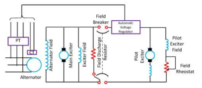
Figure 2. DC excitation
The main and the pilot exciters are driven either by the main shaft or separately driven by the motor. Direct driven exciters are usually preferred as these preserve the unit system of operation, and the excitation is not excited by external disturbances.
AC excitation
The AC excitation system consists of an alternator and thyristor rectifier bridge directly connected to the main alternator shaft. The main exciter may either be self-excited or separately excited.
Rotating Thyristor Excitation System
The rotor excitation system is shown in the figure below.
The rotating portion is being enclosed by the dashed line. This system consists an AC exciter, stationary field and a rotating armature. The output of the exciter is rectified by a full wave thyristor bridge rectifier circuit and is supplied to the main alternator field winding.
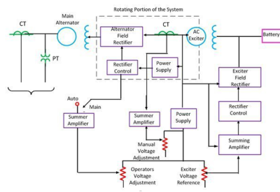
Figure3. Rotating thyristor excitation system
The alternator field winding is supplied through another rectifier circuit. The exciter voltage can be built up by using it residual flux. The power supply and rectifier control generate the controlled triggering signal. The alternator voltage signal is averaged and compare directly with the operator voltage adjustment in the auto mode of operation. In the manual mode of operation, the excitation current of the alternator is compared with a separate manual voltage adjustment.
b. Brushless Excitation System
This system is shown in the figure below. The rotating portion being enclosed by a dashed line rectangle. The brushless excitation system consists an alternator, rectifier, main exciter and a permanent magnet generator alternator. The main and the pilot exciter are driven by the main shaft. The main exciter has a stationary field and a rotating armature directly connected, through the silicon rectifiers to the field of the main alternators.
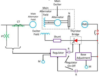
Figure4. Brushless excitation system
The pilot exciter is the shaft driven permanent magnet generator having rotated permanent magnets attached to the shaft and a three phase stationary armature, which feeds the main exciter field through silicon rectifiers, in the field of the main alternator.
The system eliminates the use of a commutator, collector and brushes have a short time constant and a response time of fewer than 0.1 seconds. The short time constant has the advantage in improved small signal dynamic performance and facilitates the application of supplementary power system stabilising signals.
3. Static Excitation System
In this system, the supply is taken from the alternator itself through a 3-phase star/delta connected step-down transformer. The primary of the transformer is connected to the alternator bus and their secondary supplies power to the rectifier and feed power to the grid control circuit and other electrical equipment.
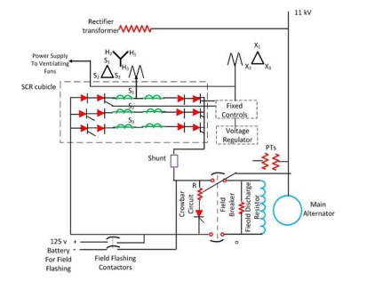
Figure 5.Static excitation using SCRs
This system has small response time and provides excellent dynamic performance. This system reduced the operating cost by eliminating the exciter windage loss and winding maintenance.
Key Takeaways:
The excitation system provides the DC voltage to the field winding of the generator and modulates this voltage for control purposes. There are many different configurations and designs of excitation systems.
Power transformers voltage regulators
- A power transformer is a static machine used for transforming power from one circuit to another without changing frequency.
- Since there is no rotating or moving part the transformer is a static device. Transformer operates on an ac supply.
- A transformer works on the principle of mutual induction.
The measure of how well a power transformer maintains constant secondary voltage over a range of load currents is called the transformer’s voltage regulation. It can be calculated from the following formula:
Regulation percentage – E no-load – E full-load/ E full-load (100%)
Bus Bars
A bus bar is defined as a conductor or a group of conductors used for collecting electric power from the incoming feeders and distribute them to the outgoing feeders. In other words, it is a type of electrical junction in which all the incoming and outgoing electrical current meets. Thus, the electrical bus bar collects the electric power at one location. The bus bar system consists the isolator and the circuit breaker.
Current limiting reactors
The current limiting reactor is an inductive coil having a large inductive reactance in comparison to their resistance which is used for limiting short circuit currents during fault conditions.
Current-voltage reactors reduce the voltage disturbances on the rest of the system. It is installed in feeders and ties, in generators leads, and between bus sections, for reducing the magnitude of short circuit currents and the effect of the respective voltage disturbance.
The main purpose of the current limiting reactor is that its reactance should not decrease when large short current flows through its windings.
Circuit breakers
A circuit breaker is a switching device that interrupts the abnormal or fault current.
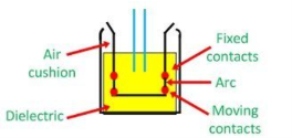
Figure 6. Circuit Breakers
Circuit breaker essentially consists of fixed and moving contacts. These contacts are touching each other and carry the current under normal conditions when the circuit is closed.
When the circuit breaker is closed, the current carrying contacts, called the electrodes engage each other under the pressure of a spring.
During the normal operating condition, the arms of the circuit breaker can be opened or closed for a switching and maintenance of the system. To open the circuit breaker, only a pressure is required to be applied to a trigger.
Protective relays
Protective relays detect abnormal conditions like faults in electrical circuits and automatically operate the switchgear to isolate faulty equipment from the system as quick as possible. This limits the damage at the fault location and prevents the effects of the fault spreading into the system.
The switch gear must be capable of interrupting both normal currents as well as fault current. The protective relay on the other hand must be able to recognize an abnormal condition in the power system and take suitable steps so that there will be least possible disturbance to normal operation.
Key Takeaways:
A power transformer is used to transfer power from one circuit to another through electromagnetic induction.
Current transformers
Current transformers are used to measure currents of high magnitude. These transformers step down the current to be measured, so that it can be measured with a normal range ammeter.
A Current transformer has one or few numbers of primary turns.
The primary winding is just a conductor, or a bus bar placed in a hollow core as shown in the figure.
The secondary winding consists of large number turns accurately wound for a specific turn’s ratio. Thus, the current transformer steps up (increases) the voltage while stepping down (lowering) the current.
The secondary current is measured with the help of an AC ammeter.
The turns ratio of a transformer is
NP / NS = IS / IP
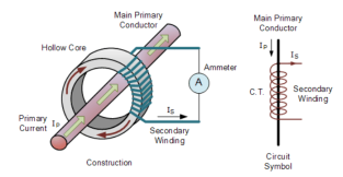
Figure 7. Current transformer
A bar-type current transformer which has 1 turn on its primary and 160 turns on its secondary is to be used with a standard range of ammeters that have an internal resistance of 0.2Ω. The ammeter is required to give a full scale deflection when the primary current is 800 Amps. Calculate the maximum secondary current and secondary voltage across the ammeter.
Secondary Current:
Is = Ip (Np/Ns) = 800 (1/160) = 5A
Voltage across Ammeter:
Vs = Is x RA = 5 x 0.2 = 1.0 volts
Potential transformer
Potential transformers known as voltage transformers are basically step down transformers with extremely accurate turns ratio. Potential transformers step down the voltage of high magnitude to a lower voltage which can be measured with standard measuring instrument. These transformers have large number of primary turns and smaller number of secondary turns.
A potential transformer is typically expressed in primary to secondary voltage ratio.
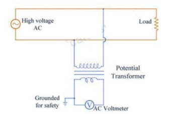
Figure 8. Potential Transformer
Lightning arresters:
The device which is used for the protection of the equipment at the substations against travelling waves, such type of device is called lightning arrester or surge diverter.
When travelling wave reaches the arrestor, its sparks over at a certain prefixed voltage as shown in the figure. The arrestor provides conducting path to the waves of relatively low impedance between the line and the ground.
The lightning arrester provides a path of low impedance only when the travelling surge reaches the surge diverter, neither before it nor after it. The insulation of the equipment can be protected if the shape of the voltage and current at the diverter terminal is like the shape shown below.
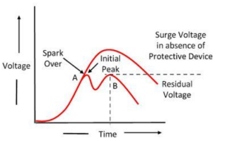
Figure 9. Voltage characteristics
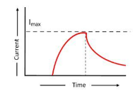
Figure 10. Current characteristics
Earthing switches
Earthing switches are safety devices which are integrals part of circuit breakers. When circuit breaker is removed and racked out the sections of the bus bar adjacent to circuit breaker are automatically earthed by means of these switches.
Earthing switching are usually in conjunction with isolators. When the isolator isolates the circuits the earthing switches make contact with bus bar and discharge any charges which gets accumulated here.
Isolators
The isolator is a mechanical switch which isolates a part of the circuit from the system as when required. Isolators are used to open a circuit under no load. Its main purpose is to isolate one portion of the circuit from the other and is not intended to be opened while current is flowing in the line. Isolators are generally used on both ends of the breaker so that repair or replacement of circuit breaker can be done without any danger.
Key Takeaways:
The primary winding of the current transformer carries the current which is to be measured whereas the primary of the potential transformer carries the voltage.
Carrier current equipment’s PLCC
Power Line Carrier Communication, often called PLCC, is used for speech data transmission as well as protection of Transmission Lines.
PLCC is mainly for telemetry and telecontrol in modern electrical Power System.
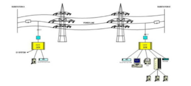
Figure11. PLCC
Power Line Carrier Communication is used for the Carrier Tripping and Direct Tripping in case of Distance Protection.
Whenever there is a fault in the line, it is important to isolate the fault. Merely tripping of breaker at one end of line cannot isolate the fault. Breaker at the other end of line should also open.
Let us consider a simple diagram as shown below.
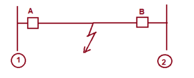
Figure 12. Fault
In case of fault, breaker A and B should open.
Let us assume that, the fault is being sensed by relay at station 1. This relay should issue trip command to breaker A and send trip signal to the remote end. This trip signal to remote end is called Direct Trip(DT) signal.
On reception of DT signal, master trip relay at Remote station 2 actuates which in turn actuates breaker B. This trip signal that is DT signal is sent through PLCC.
Control panels
Control panel is a cabinet which contains electrical components to control the motors and equipment’s.
Electrical control panels carry out these functions within manufacturing equipment.
Battery rooms
The Battery Room is a crucial element of warehouse and distribution operation.
A battery room is a facility that is used to house batteries for backup or uninterruptible power systems.
Battery rooms are found in telecommunication central offices, and to provide standby power to computing equipment in data center’s.
Metering and other control room equipment in generating station.
Generating stations are connected to each other through the electrical system sometimes called the "power grid". If one generating station can't produce enough electricity to run all the air conditioners when it's hot, another generating station can send some where it's needed.
The equipment of the control rooms, consisting of telephones and automatic indicating equipment, control desks, system diagram, frequency and time control instruments
Key Takeaways:
The Power line carrier Communication (PLCC) uses the existing power infrastructure for the transmission of data from sending to receiving end
Construction of cables :
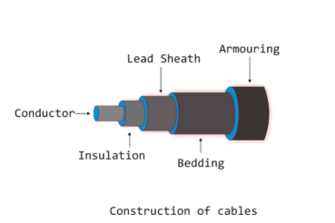
Figure13 . Cable construction
Core or Conductors
A cable contains one or more than one core conductor which depends upon the type of service intended. The conductors are made of tinned copper or aluminium and stranded to provide flexibility to the cable.
Insulators
Each core or conductor is provided with suitable thickness of insulation, the thickness of layer depends on the voltage withstood by the cable. The materials used for insulation are impregnated paper, varnished cambric or rubber mineral compound.
Metallic Sheath
To protect the cable from moisture, gases or other damaging liquids acids or alkalis in the soil and atmosphere, a metallic sheath of lead or aluminium is provided.
Bedding
Over the metallic sheath a layer of bedding is applied which consists of fibrous material like jute or hessian tape. The purpose of bedding is to protect the metallic sheath against corrosion and from mechanical injury due to armouring.
Armouring
Over the bedding, armouring is provided which consists of one or two layers of galvanised steel wire or steel tape. Its purpose is to protect the cable from mechanical injury while laying it and while handling.
Serving
To protect armouring from atmospheric conditions, a layer of fibrous material like bedding is provided over the armouring. This is known as serving.
Classification of cables:
The classification of Underground cables is done based on several criteria. Various aspects are taken while classification include:
- Number of conductors in the cable
- Voltage rating of the cable
- Construction of cable
- Type and thickness of insulation used
- Installation and Laying of the cables
Classification Based Upon Number Of Conductors In The Cable
- Single core cable
- Three core cable
Underground cable has either one, three or four cores. These cables are of course, constructed accordingly.
Underground cables are usually employed to deliver 3 phase power. A 3 cored cable is preferred up to 66 kV.
Classification Based Upon Voltage Rating of The Cable
- Low tension cables: These have a maximum voltage handling capacity of 1000 V (1 kV)
- High tension cables: These have a maximum voltage handling capacity of 11 kV.
- Super tension cables: These have a maximum voltage handling capacity of 33 kV.
- Extra hightension cables: These have a maximum voltage handling capacity of 66 kV.
- Extra super voltage cables: These are used for applications with voltage requirement above 132 kV.
Classification Based Upon Insulation Of Cable
Various insulating materials used in cable construction are Rubber, Paper, PVC, XLPE (Cross linked Polyethene) etc. Such classification is based upon operating temperature limitations.
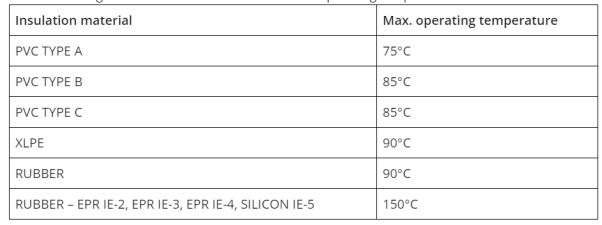
Classification Based Upon Installation and Laying Of The Cable
- Direct Buried: The conductors are buried underground in a trench without additional accessories. Sometimes cooling pipes are added if required. Once the cables are installed, there is no visible sign above the ground.
- Trough: Concrete troughs are dug, and cables are installed in them. They are visible on the surface. Maintenance is easier.
- Tunnels: Tunnels are dug up for this purpose. Such construction is mainly employed if a river needs to be crossed or if the intended power distribution is to a major city.
- Gas Insulated Lines: For cables operating at higher voltages and currents, and handling high power, such gas insulated line construction is safer. It is being employed nowadays for advanced projects.
Classification Based Upon Construction of Cable
1. Belted Cable
In such cables, the conductors are bunched together and then bounded with an insulating paper ‘belt’. In such cables, each conductor is insulated using paper impregnated with a suitable dielectric. The gaps between the conductors and the insulating paper belt are filled with a fibrous dielectric material such as Jute or Hessian. This provides flexibility as well as a circular shape.
2. Screened Cable
Further divided as H-type and S.L. - type cables.
- H-Type Cables: The three cores are individually insulated with paper and then covered by a metallic screen / cover. These metallic covers are perforated. As a result, such construction allows the three metallic screens to touch each other.
- S.L Type Cables: It is similar to the H type cables, with the difference that each of the three cores has its own lead sheath. With this provision, the need for the overall sheath used previously is eliminated.
H.S.L. Type Cables: This type of cable is combination of H type and S.L. Type cable. In these cables each core is insulated with impregnated paper and provided with separate lead sheaths.
3. Pressure Cables
For voltages beyond 66 kV, the electrostatic stresses in the cables exceed the acceptable values and solid cables become unreliable. This occurs mainly because voids are created when voltages exceed 66 kV.
XLPE cable means cross linked polyethylene insulated aluminium conductor armoured cable.In XLPE cable stranded aluminium conductor is first screened in the form of a semi conducting extrusion which provides a smooth conductor surface and prevents formation of cavities at the surface of the conductor when the cable is subjected to bending.
XLPE cable is made suitable for high voltage and extra high voltage application upto 132 kV. This cable can be used for long cable routes in high voltage transmission where the dielectric losses play a major role. This cable can easily be handled due to lighter in weight than any other high voltage cable.
Key Takeaways:
In transmission line ACSR ( Aluminium conductor steel reinforced )
AASR ( Aluminium alloy steel reinforced ) are used.
Capacitance of single core:
A single core cable is equivalent to two co-axial cylinders. The inner cylinder is conductor itself while the outer cylinder is the lead sheath. The lead sheath is always at earth potential.
Let d= Conductor diameter
D = Total diameter with sheath
The co-axial cylindrical form of cable and its section are shown in the figure.
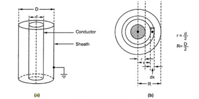
Figure 14. Capacitance of single core cable
Let Q = Charge per meter length of conductor in Coulombs
ε = Permittivity of material between core and sheath
Now ε = εo εr
Where εo = Permittivity of free space = 8.854 × 10⁻¹² F / m
εr = Relative permittivity of the medium
Consider an elementary cylinder with radius x and axial length of 1 m. The thickness of the cylinder is dx.
In Gauss’s theorem, the lines of flux emanating due to charge Q on the conductor are in radial direction and total flux lines are equal to the total electric charge possessed.
As lines are in radial direction, the cross-sectional area through which lines pass is surface area. For a cylinder with radius x, the surface area is (2 Π × axial length) m2.
Flux density = Q/surface area = Q/ 2πx C/m2
The electric field intensity at any point P on the elementary cylinder is giver by,
Gx = Dx/  where Dx = Electric flux density
= Q/ 2π x  = Q/ 2π x
  o
o  V/m
V/m
Hence the work done in moving a unit charge through a distance dx in the direction of an electric field is gx dx.
Hence the work done in moving a unit charge from the conductor to the sheath is the potential difference between the conductor and the sheath is given by,
V =  dx =
dx =  dx
dx
Q/ 2π x  o
o 
 dx /x = Q/ 2π x
  o
o  [ ln x] d/2 D/2
= Q/ 2π x  o
o  [ ln D/2 – ln d/2]
V = = Q/ 2π x  o
o  ln[D/d] = = Q/ 2π x
  o
o  ln[R/r]
The capacitance of a cable is given by,
C = Q/V = [Q/ 2π  o
o  ln (R/r)]
C = 2π  o
o  / ln[R/r] F/m = 2π
  o
o  / ln [ D/d] F/m
Capacitance of three core cable:
The Capacitance of 3 Core Cables is much more important than that of overhead line because in cables
(i) conductors are nearer to each other and to the earthed sheath
(ii) they are separated by a dielectric of permittivity much greater than that of air.
The Figure shows a system of capacitances in a 3-core belted cable used for 3-phase system. Since potential difference exists between pairs of conductors and between each conductor and the sheath, electrostatic fields are set up in the cable as shown in Figure
(i). These electrostatic fields give rise to core-core capacitances Cc and conductor-earth capacitances Ce as shown in Figure. The three Cc are delta connected whereas the three Ce are star connected, the sheath forming the star point

Figure 15. 3-core belted cable
The three delta connected capacitances Cc can be converted into equivalent star connected Capacitance of 3 Core Cables as shown in Fig. (ii).
The equivalent star capacitance Ceq is equal to three times the delta-capacitance Cc i.e. Ceq=3Cc.
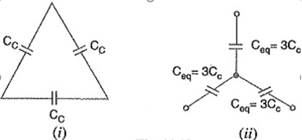
(iii) reduces to the equivalent circuit shown in Figure16.
Therefore, the whole cable is equivalent to three star-connected capacitors each of Capacitance of 3 Core Cables figure (ii)
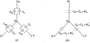
Figure 17. Delta configuration
CN = Ce + Ceq
= Ce + 3Cc
If Vph is the phase voltage, then charging current IC is given by ;
Ic = Vph / Capacitive reactance per phase
= 2π f Vph CN
= 2πfVph(Ce+3Cc)
Measurements of Ce and Cc
(i) In the first measurement, the three cores are bunched together that is common and the capacitance is measured between the bunched cores and the sheath. The bunching eliminates all the three capacitors Cc, leaving the three capacitors Ce in parallel.
Therefore, if C1 is the measured capacitance, this test yields :
C1 = 3 Ce
Ce = C1/3
Knowing the value of C1, the value of Ce can be determined.
(ii) In the second measurement, two cores are bunched with the sheath and capacitance is measured between them and the third core. This test yields 2Cc + Ce. If C2 is the measured Capacitance of 3 Core Cables, then,
C2 = 2 Cc + Ce
As the value of Ce is known from first test and C2 is found experimentally, therefore, value of Cc can be determined.
Key Take Aways:
A Capacitance of Single Core Cable can be equivalent to two long co-axial cylinders.
Under operating conditions, the insulation of a cable is subjected to electrostatic forces. This is known as dielectric stress. The dielectric stress at any point in a cable is in fact the potential gradient or electric intensity at that point.
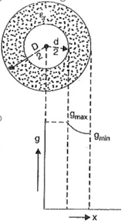
Figure 18. Single core cable.
Consider a Capacitance of Single Core Cable with core diameter d and internal sheath diameter D. The electric intensity at a point x metres from the centre of the cable is
Ex = Q/2π 
 x volts/m.
By definition, electric intensity is equal to potential gradient. Therefore, potential gradient g at a point x metres from the centre of cable is
g=Ex
g=Q/2π 
 x -------------------------------(i)
The potential difference V between conductor and sheath is
V = Q/ 2π 
 log e D/d
Q = 2π 
 V / log e D/d -----------------------------(ii)
Substituting the value of Q from exp. (ii) in exp. (i), we get,
g = = 2π 
 V / log e D/d / 2π
 x = V / x log e D/d -----------------(iii)
It is clear from exp. (iii) that potential gradient varies inversely as the distance x. Therefore, potential gradient will be maximum when x is minimum i.e., when x = d/2 or at the surface of the conductor. On the other hand, potential gradient will be minimum at x = D/2 or at sheath surface.
Maximum potential gradient is
Gmax = 2V / d log e D/d volts/m
Minimum potential gradient is
Gmin = 2V/ D log e D/d volts/m
Key Takeaways:
Under operating conditions, the insulation of a single core cable is subjected to electrostatic stress, called the dielectric stress.
Grading is defined as the process of equalizing the stress in the dielectric of the cable. Generally, the electrical stress is maximum at the surface of the conductor or the innermost part of conductor while it is minimum at the outermost sheath of the conductor.
If the stress is equal to all the dielectric of the conductor, then the thickness of the conductor is reduced. But if the stress is maximum at any of the dielectrics then it increases the thickness of the cable due to which the cost of the cable also increases. There are two methods of grading the cable
- Capacitance Grading
- Intersheath Grading
Key Takeaways:
Grading of cable is the process of achieving uniform distribution of dielectric stress or voltage gradient in a dielectric of cable.
Intersheath Grading
In this method, instead of using various dielectrics and having a composite dielectric, we use a homogeneous dielectric material. However, to distribute the stress properly, we use extra metallic sheaths between the conductor and the main sheath. These intermediate sheaths are called ‘intersheaths’. These intersheaths are then held at adequate voltage levels. This method improves voltage distribution in the dielectric of the cable and consequently uniform potential gradient is obtained.
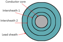
Figure 19. Intersheath grading
Capacitance grading
Capacitance grading is done by employing various layers of different dielectrics having different permittivity’s between the core and the sheath. Hence the dielectric insulation provided is no longer homogeneous, but composite.
The various layers are arranged so that the permittivity decreases from the surface of the conductor to the sheath of a cable that is the permittivity of dielectric is inversely proportional to the distance from the center.
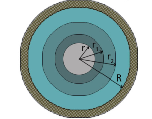
Figure 20. Capacitance grading
Key Takeaways:
Intersheath grading is the method of keeping the gradual voltage across the insulator by using the layers of the insulators.
The process of achieving uniformity in the dielectric stress by using layers of different dielectrics is known as capacitance grading.
References:
1. Power System Engineering Book by D.P. Kothari and I.J. Nagrath
2. Power System Analysis and Design Book by J. Duncan Glover and Mulukutla S Sarma
3. A Course In Power Systems Book by J. B. Gupta
4. Modern Power System Analysis Book by D.P. Kothari and I.J. Nagrath
5. Electrical Power Systems Book by Murty P.S.R
6. Elements of Power System Analysis Book by William D. Stevenson