Unit 3
Mechanical Design of Overhead lines and Insulators
An overhead line may be used to transmit or distribute electric power. The successful operation of an overhead line depends to a great extent upon the mechanical design of the line. In general, the main components of an overhead line are:
(i) Conductors which carry electric power from the sending end station to the receiving end station.
(ii) Supports which may be poles or towers and keep the conductors at a suitable level above the ground.
(iii) Insulators which are attached to supports and insulate the conductors from the ground.
(iv) Cross arms which provide support to the insulators.
(v) Miscellaneous items such as phase plates, danger plates, lightning arrestors, anti-climbing wires etc.
Key Takeaways:
An overhead power line is a structure used in electric power transmission and distribution to transmit electrical energy across large distances.
The different line supports used by transmission lines include,
(a) Wooden Poles
(b) Reinforced concrete poles
(c) Steel poles
(d) Latticed steel towers.
The choice of support depends upon the cost, span of line, atmospheric conditions and line voltage.
(a) Wooden Poles-Type of Electrical Poles
When compared to different types of line supports wooden poles are cheap and are used for lines of shorter spans about 50 meters, best suited for rural areas.They can withstand voltage up to 132 kV When, single or H type poles, are used whereas double pole structures of ’A or H type provide higher transverse strength and are usually used for terminal poles.
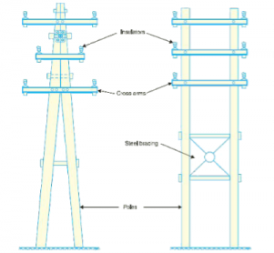
Figure1 . Wooden poles
(b) Reinforced concrete poles(RCC Poles)-Type of Electrical Poles
These poles are widely used because of their longer durability and are used for system 33 kV. They have greater mechanical strength, used for longer spans, longer- life and maintaining cost is very low. They also have good insulating properties am appearance. RCC pole structure is shown in the figure.
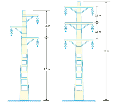
Figure 2. RCC poles
(c) Steel Poles-Type of Electrical Poles
These poles are used for distribution purposes along roadsides and developed areas. They need to be galvanized or painted periodically to prolong its life and prevent them from corrosion and hence maintenance cost is high. They are often used as the substitute for wooden poles.
(d) Latticed Steel Tower-Type of Electrical Poles
Where long span of lines are essential, steel towers are used for long-distance transmission at voltages above 33 kV, Owing to longer span, insulation cost and risk of interrupted service is reduced to a large extent. Lightning troubles and breakdowns are reduced considerably as the tower footing are grounded into the earth. These towers are made of‘steel, have longer-life, high mechanical strength and ability to withstand severe climatic conditions.
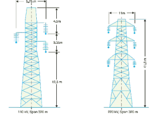
Figure 3. Lattice steel power.
.
Key Takeaways:
The different types of structure (poles or towers) used for supporting the overhead lines or wires, such types of structures are called line supports.
The spacing of conductors is determined by considerations, which are partly electrical and partly mechanical.
Usually conductors will swing synchronously (in phase) with the wind, but with long spans and small size of conductors, there is always possibility of the conductors swinging non- synchronously, and the size of the conductor and the maximum sag at the centre of the span are factors, which should be considered in determining the phase distance apart at which they should strung.
As a rule of thumb, minimum horizontal spacing between conductors should not be less than 1% of the span length in order to minimize the risk of phases coming into contact with each other during swing.
Key Takeaways:
The minimum distance between bottom conductor and ground of a 400KV transmission line is 8.84 meter.
The distance between the two adjacent poles is known as span length. It is generally denoted by 'l' (L) and specified in meters.
The location of the supports (towers) depends upon the profile of the land along which transmission line is to be run. This means the span length may not be equal.
When successive spans are unequal, changes in load or temperature will bring unequal changes in tension in the different span.
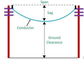
Figure 4. Length of span
Therefore, it is necessary to have calculations assuming uniform tension in the conductor between the two tension towers.
Equivalent span length L = √ l1 2 + l2 2 + l3 2 / l1 + l2 + l3
Where L1, L2, L3 are the lengths of the individual spans between the two tension towers.
Key Takeaways:
The distance between the two adjacent poles is known as span length
i)Sag calculation when supports are at equal levels:
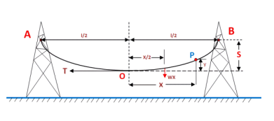
Figure 5. Equal sag
Let
A conductor is in the two equal level supports A and B.
O is the lowest point of the conductor.
l= length of the span.
w= weight per unit of length conductor.
T= Tension in the conductor.
A point has been considered on the conductor in the point P which is X length away from the point O & y length high from the bottom point of the conductor. It may be assumed that the curvature length ‘OP’ = x, and the following two forces will be acted on the portion ‘OP’ of the conductor.
- Weight of ‘OP’ portion conductor is WX which is acted at a distance x/2 from the point O.
- T tension is acted at point O.
The above two forces is equating movement about point O, we get
Ty = Wx X x/2
Y = wx 2 / 2T -----------------------------------------(i)
The value of y is the sag of conductor at point P.
As, at the support point A, x = l/2 and y = S,
Therefore, put the value of x and y in the equation (i), we get
Sag(s) = w(1/2) 2 / 2T = w l 2/ 8T
Ii)Sag calculation when support are at unequal level:
The unequal level suspension conductor is normal shown in hilly area.
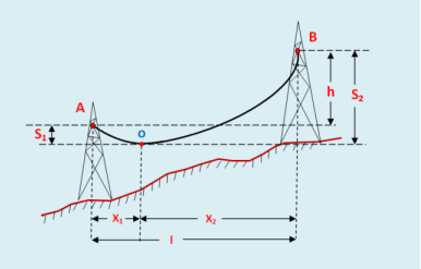
Figure 6 . Sag at unequal support
Let,
A conductor is supported at two point A & B.
O is the lowest point of conductor.
l = Span length of conductor.
h = Different in levels between two supports
X1 = Distance of support at higher level A from & point O
X2 = Distance of support at higher level i.e B from O.
T = Tension in conductor,
W= Wight per unit length of the conductor.
Sag, S1 = wx1 2 / 2T
Sag S2 = wx2 2 / 2T
Also x1 + x2 = l --------------------------(i)
Now S2 -S1 = w/2T( x2 2 – x1 2)
= w/2T( x2 +x1)(x2-x1)
S2 -S1 =wl/2T(x2-x1)
(x2-x1) = 2Th /wl -------------------------(ii)
Solving (i) and (ii) we get
x1 = l/2 – Th/wl
x2 = l/2 + Th/wl
After getting x1 & x2 value, the sag of conductor is easily calculated.
Effect of wind and ice loading:
The weight of ice acts in the same direction as the weight of conductor ( i.e vertically down wards ). The force due to the wind is assumed to act horizontally.
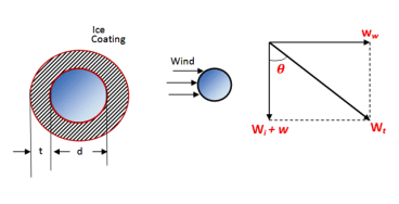
Figure 7. Effect of wind and ice loading
Lets,
w= weight of conductor per unit length
= conductor material density x volume per unit length
Wi = weight of conductor per unit length
= density of ice x volume of ice per unit length
= density of ice x π/4 [ (d + 2t) 2 – d 2] x 1
= density of ice x π/4 [ (d 2 + 2.d.2t + 4t 2 – d 2]
= density of ice x π/4(4 dt + 4t 2 )
= density of ice x πt(d + t )
W w = wind force per unit length
= wind force per unit area x projected area per unit length
= wind pressure x [(d +2t) x 1]
Therefore, the total force on conductor is the vector sum of the above two forces which is shown in fig.
Wt = √ (w+wt) 2 +(ww) 2
And tan  = w w / w + wi
So, when the conductor has wind and ice loading
i) the sag of the conductor will be:-
S = w t l 2 / 2T
This sag represents the slant sag in a direction making an angle θ to the vertical. We can easily calculate the value of slant slag by using the above formula.
ii) The vertical sag = S cos ϴ
Key Take Aways:
To Calculate the Sag in an overhead transmission line for two cases.
- Case1: When the conductor supports are at equal level.
- Case2: When the conductor supports are at unequal level.
There are several Types of Insulators in Transmission Lines but the most commonly used are pin type, suspension type, strain insulator and shackle insulator.
1. Pin Type Insulator:
The part section of a pin type insulator is shown in Fig.(i). The pin type insulator is secured to the cross-arm on the pole. There is a groove on the upper end of the insulator for housing the conductor. The conductor passes through this groove and is bound by the annealed wire of the same material as the conductor.
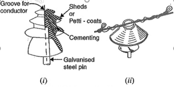
Figure 8. Pin type Insulator
Pin type insulators are used for transmission and distribution of electric power at voltages upto 33 kV. Beyond operating voltage of 33 kV, the pin type insulators become too bulky and hence uneconomical.
2. Suspension Type Insulator:
The cost of pin type insulator increases rapidly as the working voltage is increased. For high voltages (>33 kV), it is a usual practice to use suspension type insulators shown in Figure. They consist of several porcelain discs connected in series by metal links in the form of a string. The conductor is suspended at the bottom end of this string while the other end of the string is secured to the cross arm of the tower. Each unit or disc is designed for low voltage, say 11 kV. The number of discs in series would obviously depend upon the working voltage. For instance, if the working voltage is 66 kV, then six discs in series will be provided on the string.
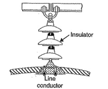
Figure 9 . Suspension Type Insulator
Strain insulators:
When there is a dead end of the line or there is corner or sharp curve, the line is subjected to greater tension. In order to relieve the line of excessive tension, strain insulator9s are used.
For low voltage lines (< 11 kV), shackle insulators are used as strain insulators. However, for high voltage transmission lines, strain insulator consists of an assembly of suspension insulators as shown in Figure. The discs of strain insulators are used in the vertical plane. When the tension in lines is exceedingly high, as at long river spans, two or more strings are used in parallel.
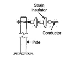
Figure 10. Strain insulator
4. Shackle insulators:
In early days, the shackle insulators were used as strain insulators. But now a days, they are used for low voltage distribution lines. Such insulators can be used either in a horizontal position or in a vertical position. They can be directly fixed to the pole with a bolt or to the cross arm. Figure shows a shackle insulator fixed to the pole. The conductor in the groove is fixed with a soft binding wire.
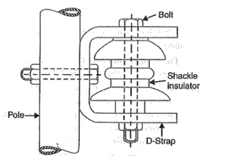
Figure11. Shackle insulator
Post insulator
These insulators are used in the substations because it is appropriate for different voltage levels. It is arranged in a vertical position and protects transformers, switch gear and other connecting devices. The mechanical strength of these insulators is strong.
Bushing:
In electric power, a bushing is a hollow electrical insulator that allows an electrical conductor to pass safely through a conducting barrier such as the case of a transformer or circuit breaker without making electrical contact with it.
Key Takeaways:
An insulator gives support to the overhead line conductors on the poles to prevent the current flow toward earth
A string of suspension insulator consists of number of porcelain discs connected in series through metallic links. Fig. (i) shows 3-disc string of suspension insulator. The porcelain portion of each disc is in between two metal links. Therefore, each disc forms a capacitor C as shown in Fig.(ii). This is known as mutual capacitance or self-capacitance.
If there were mutual capacitance alone, then charging current would have been the same through all the discs and consequently voltage across each unit would have been the same i.e., V/3 as shown in Fig.(ii).
However, in actual practice, capacitance also exists between metal fitting of each disc and tower or earth. This is known as shunt capacitance C1. Due to shunt capacitance, charging current is not the same through all the discs of the string [fig. (iii)].
Therefore, voltage across each disc will be different. Obviously, the disc nearest to the line conductor will have the maximum voltage. Thus, referring to Fig. (iii), V3 will be much more than V2 or V1.
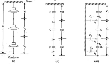
Figure 12. Potential distribution
Key Takeaways:
The suspension insulator separates the line conductors and supports them electrically.
String efficiency
The ratio of voltage across the whole string to the product of number of discs and the voltage across the disc nearest to the conductor is known as string efficiency i.e.,
String efficiency = Voltage across the string / n x Voltage across disc nearest to conductor
Methods of improving string efficiency
The various methods for this purpose are :
1.By using longer cross-arms. The value of String Efficiency of Insulator depends upon the value of K that is ratio of shunt capacitance to mutual capacitance.In order to reduce shunt capacitance, the distance of conductor from tower must be increased that is longer cross-arms should be used.
2.By grading the insulators. In this method, insulators of different dimensions are so chosen that each has a different capacitance. The insulators are capacitance graded that is they are assembled in the string in such a way that the top unit has the minimum capacitance, increasing progressively as the bottom unit that is nearest to conductor is reached. Since voltage is inversely proportional to capacitance, this method tends to equalize the potential distribution across the units in the string.
3.By using a guard ring. The potential across each unit in a string can be equalized by using a guard ring which is metal ring electrically connected to the conductor and surrounding the bottom insulator. The guard ring introduces capacitance between metal fittings and the line conductor.. The guard ring is contoured in such a way that shunt capacitance currents i1,i2 etc. are equal to metal fitting line capacitance currents i′1,i′2 etc. The result is that same charging current I flows through each unit of string. Consequently, there will be uniform potential distribution across the units.
Key Takeaways:
The string efficiency is defined as the ratio of voltage across the string to the product of the number of strings and the voltage across the unit adjacent string.
References
1. Power System Engineering Book by D.P. Kothari and I.J. Nagrath
2. Power System Analysis and Design Book by J. Duncan Glover and Mulukutla S Sarma
3. A Course In Power Systems Book by J. B. Gupta
4. Modern Power System Analysis Book by D.P. Kothari and I.J. Nagrath
5. Electrical Power Systems Book by Murty P.S.R
6. Elements of Power System Analysis Book by William D. Stevenson