Unit 4
Resistance and Inductance of Transmission Line
The conductors of the transmission lines have small resistance. For short lines, resistance plays an important role. As the line current increases so do the ohmic loss (I2R loss). When the current exceed a certain value the heat generated due to ohmic loss starts to melt the conductor and the conductor becomes longer that results in more sag.
The current at which this condition of conductor is irreversible is called thermal limit of conductor.
The resistance R of a conductor of length 'l' and cross section 'a' is given by the formula
R = ρl/a ----(1)
Here ρ is the resistivity of the conductor material which is a constant.
Key Takeaways:
Resistance in this parameter of any transmission line relies on the cross-sectional area of the conducting material.
When an Alternating Current flow through a conductor, it is not distributed uniformly throughout the conductor cross-section. AC current tends to concentrate near the surface of the conductor. This phenomenon in alternating currents is called as the skin effect.
The alternating flux in a conductor is caused by the current of the other nearby conductor. This flux produces a circulating current or eddy current in the conductor which results an apparent increase in the resistance of the wire and thus, more power losses in the windings. This phenomenon is proximity effect.
Factors responsible for production of these effects:
The skin effect depends upon the following factors:
- Conductor material: Better conductors and ferromagnetic materials experience higher skin effect
- Cross-sectional area of the conductor: skin effect increases with increase in the cross-sectional area
- Frequency: increases with increase in the frequency
- Shape of the conductor: skin effect is lesser for stranded conductors than solid conductors.
Following are the factors on which proximity effect depends on:
- This effect increases with increase in frequency.
- More the diameter of conductor, the more will be this effect.
- This effect also depends on the material of conductor. If the material is of ferromagnetic nature, proximity effect will be more.
- Proximity effect is more in case of solid conductor. This is the reason, stranded or ACSR conductors are used to reduce this effect.
Key Takeaways:
Skin effect is the tendency for high-frequency currents to flow on the surface of a conductor. Proximity effect is the tendency for current to flow in other undesirable patterns
Flux linkages due to internal flux:
In the figure (ii) where the X-section of the conductor is shown magnified for clarity. The magnetic field intensity at a point x metres from the centre is given by;
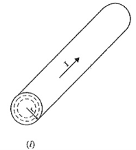
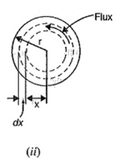
Figure 1. Flux linkage
*Hx = Ix / 2  x
x
Assuming a uniform current density,
Ix = π x 2 / π r 2 . I = x 2 / r 2 I
Hx = x 2 / r2 x I x 1/ 2 π x = x/ 2 π r 2 . I AT/m
If μ ( = μ0μr ) is the permeability of the conductor, then flux density at the considered point is given by;
Bx = μo μr Hx wb/ m2
= μo μr x / 2 π r 2 I = μo x I / 2 π r 2 wb/m2
Now, flux dΦ through a cylindrical shell of radial thickness dx and axial length 1 m is given by;
dɸ = Bx x 1 x dx = μo x I / 2 π r 2 dx weber
This flux links with current
Ix = I π x 2 / π r2
Therefore, flux linkages per metre length of the
dѰ = π x 2 / π r 2 dɸ = μo Ix 3 / 2 π r 4 dx weber-turns
Total flux linkages from centre upto the conductor surface is
Ѱ int =  I x 3 / 2 π r 4 dx
= = μo I / 8 π weber turns per metre length
Flux linkages due to external flux: To calculate the flux linkages of conductor due to external flux. The external flux extends from the surface of the conductor to infinity. Referring to Figure, the field intensity at a distance x metres (from centre) outside the conductor is given by ;
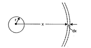
Figure 2. Flux linkage due to external flux
Hx = ½ π x AT/m
Flux density Bx = μo Hx = μoI/ 2πx wb/ m2
Now, flux dΦ though a cylindrical shell of thickness dx and axial length 1 metre is
dɸ = Bx dx = μoI/ 2πx dx webers
The flux dΦ links all the current in the conductor once and only once.
dѰ = dɸ = μoI/ 2πx dx weber- turns
Total flux linkages of the conductor from surface to infinity,
Ѱ ext =  I / 2 π x dx webers-turns
Overall flux linkages,
Ѱ= Ѱ int + Ѱ ext = μoI/ 8π +  / 2π x dx
Ѱ =  I / 2π [ ¼ +
  ] wb-turns/m length
Key Takeaways:
The inductance of a circuit is defined as the flux linkage per unit current. Therefore, to find the inductance of a circuit, the determination of flux linkage is of primary importance.
Consider a single phase overhead line consisting of two parallel conductors A and B spaced d metres apart as shown in Figure. Conductors A and B carry the same amount of current (i.e. IA = IB), but in the opposite direction because one forms the return circuit of the other.
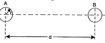
Figure 3. Inductance of single phase
IA +IB =0
In order to find the inductance of conductor A (or conductor B), we shall have to consider the flux linkages with it. There will be flux linkages with conductor A due to its own current IA and also due to the mutual inductance effect of current IB in the conductor B.
Flux linkages with conductor A due to its own current
= μoIA/2π ( ¼ +  --------------------------------(i)
Flux linkages with conductor A due to current IB
= μoIB/2π  ------------------------------------------(ii)
Total flux linkages with conductor A is
ѰA = exp(i) + exp(ii)
= μoIA/2π ( ¼ +  ) + μoIB/2π
= μo/2π [ ( ¼ +  ) IA + IB
  ]
]
= μo/2π [ (¼ + log e  - log e r ) IA + ( log e
  - log e d) IB ]
= μo/2π [ (IA/4 + log e ∞(IA+IB) – IA log e r – IB log e d)]
= μo/2π [ (IA/4 + log e r – IB log e d)] ( Since IA + IB=0)
IA + IB =0 or -IB = IA
-IB log e d = IA log e d
ѰA = μo/2π[ IA/4 + IA log e d – IA log e r] wb-turns/m
= μo/2π[ IA/4 + IA log e d/r ]
= μoIA/2π[ ¼ + log e d/r]
Inductance of conductor A,
LA = ѰA/IA
= μo/2π[ ¼ + log e d/r] H/m
= 4π x 10 -7 / 2 π [ ¼ + log e d/r ] H/m
LA = 10 -7 [ ½ + 2 log e d/r] H/m -----------------------------(i)
Loop inductance = 2LA H/m = 10-7 [ 1 + 4 log e d/r] H/m
Loop inductance = 10 -7 [ 1+4 log e d/r] H/m ------------------------(ii)
Note that eq.(ii) is the Inductance of Single Phase Two Wire System and is sometimes called loop inductance.
Key Takeaways:
When an alternating current flows through such a loop, a changing magnetic flux is set up. The changing flux links the loop and hence the loop (or single phase line) possesses inductance.
Transposition cycle is to change the arrangement of the transmission line cables every specific length (about100Km) to avoid unbalance due to the unsymmetric of the distances between the cables so the impedance will change and hence current in each phase which leads to unbalance so if we change the position of cables every100 Km the cables impedance will be symmetrical across the line and unbalance is avoided.
Key Takeaways
Transposition is the periodic swapping of positions of the conductors of a transmission line , in order to reduce cross talk and otherwise improve transmission
Inductance of symmetrical three-phase line
In symmetrical three-phase line, all the conductors are placed at the corners of the equilateral triangle. Such an arrangement of conductors is also referred to as equilateral spacing. It is shown in the diagram below
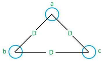
Figure4. Symmetrical three phase inductance line
Let the spacing between the conductors be D and the radius of each conductor, r. The flux linkages of conductor a is given by the equation:
λa=2x10 -7 ( Ia Iղ 1/Daa + Ib ղ 1/Dab + Ic Iղ 1/Dac )
In this case
Dab = Dbc= Dac = D
Daa = r’
λa=2x10 -7 (Ia Iղ I/r’ + Ib Iղ 1/D + Ic .1/D)
For a three-wire system, the algebraic sum of the currents in the conductors is zero.
Ia + Ib + Ic =0
Ia = -Ib -Ic
Ia = -(Ib+Ic)
So, the flux equation becomes
λa=2 x 10 -7 x ( Ia In 1/r’ +(Ib + Ic) In I/D)
λa=2x10 -7 ( Ia In 1/r’ – Ia In 1/D)
= 2 x 10 -7 x Ia( In 1/r’ – In I/D)
By using the formula ln m – ln n = ln m/n . The inductor of conductor, ‘a’ is
λa=λ/Ia = 2 x 10 -7 ln D/r’ H/m
The inductance of conductors b and c will also be the same as that of a. The inductance of the three-phase line is equal to the two-wire line.
Inductance of unsymmetrical three-phase line
Consider a three-phase unsymmetrical line, having different spacing between their conductors where the radius of each conductor is r. It is shown in the diagram below
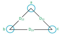
Figure 5.Unsymmetrical three phase line
Flux linkage in ‘a’ is expressed by the formula
λ a1= 2 x 10 -7 ( Ia ln 1/r’ + Ib ln 1/D12 + Ib In 1/D31)
Flux linkage in conductor ‘a’ due to ‘b’ is given by the formula
λ a2= 2 x 10 -7 ( Ia ln 1/r’ + Ib ln 1/D23 + Ic In 1/D12)
Flux linkage in conductor ‘a’ due to ‘c’ is given by
λ a3= 2 x 10 -7 ( Ia ln 1/r’ + Ib ln 1/D23 + Ic In 1/D23)
The average value of flux linkages of ‘a’ is
 a = 1/3 (λ a1+λa2+λc)
λa= 2/3 x 10 -7 [( Ia ln 1/r’ + Ib ln 1/D13 + Ic In 1/D31) +(Ia ln 1/r’ +Ib ln 1/D23+I12 1/ D12) + (Ia ln 1/r’ +Ib ln 1/D31+Ic ln 1/D23)]
λa=2/3 x 10 -7 [ 3Ia ln 1/r’ +Ib ln 1/D12D23D31+Icln 1/ D12D23D31]
λa=2/3 x 10 -7 [ 3Ia ln 1/r’ – Ia ln 1/ D12D23D31]
Since for balanced conditions
Ia + Ib + Ic =0
Ib + Ic = -Ia
λa=2 x 10 -7 [ Ia ln 1/r’ +1/3 Ia ln ( D12D23D31)]
By using formula
½ ln m = ln m ½
λa=2 x 10 -7 Ia ln ( D12D23D31) 1/3 / r’
The average inductance of phase a is
La = λa/Ia = 2 x 10 -7 x ln (D12 D23 D31) 1/3 /r’ H/m
Similarly,
Lb = Lc = 2 x 10 -7 x ln (D12 D23D31) 1/3 / r’ H/m
Thus, it is found that the values of the inductance for the three phases are equalized by transpositions.
Key Takeaways:
With asymmetrical spacing between the phases, the voltage drop due to line inductance will be unbalanced even when the line currents are balanced.
Refer …..5.4
• In extra high voltage (EHV) transmission line, bundle conductors (use more than one conductor per phase) are used to reduce the effect of corona.
• Figure below shows common EHV bundles consisting of two, three, or four conductors.
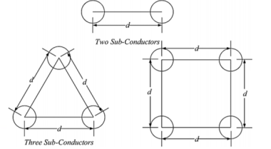
Figure 6. Inducatnce of bundled conductors
Where the small letter of 𝑑 is the bundle spacing.
• To calculate inductance of bundle conductor, the equation below is considered;
La = Ѱa/Ia = 2 x 10 -7 ( ln 3√ D12D23D1/ r’) H/m
La = 2 x10⁻⁷ ln Deq/Ds H/m
Where Deq= 3√D12D23D31; Ds =r’
Ds in above equation is replaced by GMR of the bundle which is denoted by DSL b
For two conductor bundle:
DSL b = 2 2 √ (Ds x d) 2 = 4√ (Ds x d 2 ) = √ (Ds x d)
For three conductor bundle:
DSL b = 3 2 √ (Ds x dxd) 3 = 9√ (Ds x d 2 ) 3 = 3√ Ds x d 2
Key Takeaways:
A bundled conductor reduces the reactance of the electric transmission line.
References
1. Power System Engineering Book by D.P. Kothari and I.J. Nagrath
2. Power System Analysis and Design Book by J. Duncan Glover and Mulukutla S Sarma
3. A Course In Power Systems Book by J. B. Gupta
4. Modern Power System Analysis Book by D.P. Kothari and I.J. Nagrath
5. Electrical Power Systems Book by Murty P.S.R
6. Elements of Power System Analysis Book by William D. Stevenson