Unit - 2
Substation and Earthing
The substations may be classified in numerous ways such as on the basis of
- Nature of duties
- Service rendered
- Operating voltage
- Importance
- Design
Nature of duties
A] Setup for primary substations: Such substations are usually associated with generating stations The generated voltage which is usually low is stepped up to primary transmission voltage so that the use blocks of power can be transmitted over long distances to the load centers economically.
B] Primary grid substation: Search substations are located at suitable load centers along the primary transmission lines. In the substations, the primary transmission voltage is stepped down two different suitable secondary voltages.
C] Step down or distribution substations: Search substations are located at the load centers where the sub-transmission/primary distribution voltage is step down to secondary distribution voltage. These are the substations that feed the consumers through a distribution network and service lines.
Service rendered:
A] T/F substation: T/F is installed on such substations to transform the power from one voltage level to another level as per needs.
B] Switching substations: such substations are made for switching operation of power lines without transforming the voltage point at such substations different connections are made between various transmission lines.
C] Converting substation: such substations are meant for either converting AC to DC or vice versa for converting frequency from higher to lower or vice versa.
Operating voltage:
A] High voltage substation: Involving voltage is between 11 kV & 66kV.
B] Extra High voltage substation: Involving voltage is between 1321KV to 400KV.
C] Ultra High voltage substation: Operating on voltage above 400KV.
Importance:
A] Grid substations: These are the substations from where bulk power is transmitted from one point to another point in the grid. These are important because any disturbance in the substation main causes the failure of the grid.
B] Town substations: The substation step down the voltages at 33/11 KV for further distributions in the towns and any failure in such substations results in the failure of supply for the whole of the town.
Design:
A] Indoor type substation: in such substations, the apparatus is installed within the substation building. Such substations are usually for a voltage up to 11KV but can be erected for the 33kV & 66kV.
B] Outdoor substations:
- Pole mounted substation: search substations are selected for distribution of power in localities. Single stout pole or H-pole and L-pole structures with suitable platforms are employed for T/F of capacity up to 25kVA,125kVA.
- Foundation mounted: For T/F of capacity above 250KVA the T/F are too heavy for pole mounting. Such substations are usually for voltages of 33,000 volts & above.
Indoor substations
- In these substations, the apparatus is installed within the substation building.
- Such substations are usually for a voltage up to 11000V but can be erected for 33000V & 66000V.
- The switchgear on supply or primary side will consist of oil circuit breakers only.
- The High voltage supply is given to the primary of the T/F through C.B.
- From the bus bar, various feeders emerged out. The panel for each feeder consists of an isolator switch and C.B.
- In addition to isolator and C.B., the panel is provided with the measuring instrument.
- As regards the protection of feeders usually reverse power relay is employed.
- For the protection of oil-filled T/F with Conservator tanks, Buchholz's relay is most common.
- The auxiliary of the indoor type of substations is storage batteries. Firefighting equipment such as water buckets, fire extinguishers, etc.
- The batteries are used for the operation of protective gear and switch operating solenoids. Emergency lighting in S/S in case of failure of supply.
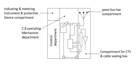
- The several compartments in which the indoor S/S is divided our control compartment, indicating and metering instruments and protective device compartment, C.B. & operating mechanism compartment, main busbar compartment and C.T. And cable sealing box compartment as shown in figure
Outdoor substations:
Pole mounted substation:
- Such substations are elected for mounting distribution T/F of capacity up to 250KVA search substations are the cheapest, simple and smallest type of substation.
- All the equipment is of outdoor type and mounted on the supporting structure of height distribution line
- Triple pole mechanically operated switch is used for switching on and off of height transmission line-height fuse unit is installed for protection of height side.
- To control the LT side ironclad look tension switch of suitable capacity with fuse is installed.
- Lighting arresters are installed over the height line to protect the T/F from surges substation is earth at two or more places.
- Generally, T/F of capacity up to 125 kVA is mounted on double pole structure, and for T/F of capacity above 125 kVA but not exceeding 260KVA 4 pole structure with a suitable platform is used.
- This type of pole-mounted substation is erected in a very thickly populated location.
Foundation mounted substation:
- These substations are built entirely in the open and such substation, all the equipment is assembled into 1 unit usually enclosed by a fence from the point of view of safety.
- The substation for primary and secondary transmission and secondary distribution are foundation mounted outdoor types.
- Since equipment required for such substation is heavy, therefore site selected for the substation must have a good SRS for heavy transport.
- Again, owing to expose bus bars and other associated equipment the clearance and spacing are not only to be governed by the operating voltage but also from the consideration of the enrollment from outside.
- Low-level type substations are designed except when the space available is limited as these provide the facility of easy inspection, cleaning, and maintenance.
- The switchgear consists of C.B. Of suitable type on both the side but with the increased reliability of the modern T/F the practice is to dispense with the C.B. On the incoming side from the economic consideration. The isolating switches thus serve the purpose.
SR. No. | Equipment | Location | Function |
1 | Bus bars | Supported on post insulator or strain insulator | To receive power from the incoming circuit and to deliver power to the outgoing circuit |
2 | Surge arresters | Connected between phase conductors and ground | To discharge overvoltage surges to earth. |
3 | Isolators | Located on each side of C.T. | To provide isolation from Life parts for maintenance |
4 | Earthing switch | Mounted on the frame of the isolators | For safety purpose, it discharges the voltage on the circuit to earth |
5 | Circuit Breaker | At every switching point. At both ends of protection zones. | Switching off the part during the abnormal condition and reconnect or normal condition. |
6 | C.T. | Protective or measuring C.T. Location decided by protective zone measurement requirement | Step down current measurement protection and control. |
7 | P.T. | Located on the feeder side of C.B. | Step down voltage is for measurement, protection, and control.
|
8 | Power T/F | At generating station, the receiving station. | To set up voltage for the transmission line, to step down for feeder line. |
9 | Shunt reactors | Transmission line | During a low load, period to control voltage of long extra High voltage lines. Also, to compensate shunt capacitance of transmission line during low load period. |
10 | Shunt capacitors | Located at receiving stations and distribution substations. | To improve P.F. By compensating reactive power point. |
11 | Series capacitors | Bank located at sending and/or receiving and offline | To improve power transferability in EV long line. |
12 | Carrier equipment | Mounted above CVT or a separate structure | Use for protection and communication signals. |
13 | Switchgear | Located inside switchgear building | To provide AC power to the auxiliary station lighting system. |
14 | Station earthing system | Connected to equipment earthing and neutral point earthing | To provide low resistance earthing for discharge current from search arresters earthing switches. |
15 | Insulators | On cross across | To support conductors. |
Busbar arrangements in the substations:
Single busbar system:
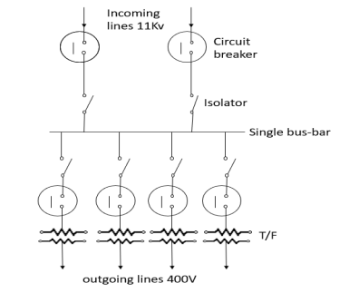
Incoming and outgoing lines are connected to a single bus bar. This is used in power stations and small indoor stations 11KV incoming lines are connected through C.B. To a single bus bar. Isolators are also connected as shown
Advantages:
- Low cost
- Less maintenance
- Simple operations
Disadvantages:
- For maintenance complete unit is to be shut off.
- If the bus bar becomes faulty the whole unit is disturbed.
- Large fault currents.
Sectionalized bus-bar system:
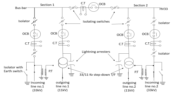
In large stations it is not advisable to keep the full system for the fault occurring in one of the sections. To avoid this, the system is divided into several sections so that the faulty section can be isolated, and the remaining section can give the service. This system is well suited for the 33KV HV line stepping down to 11 KV feeder lines.
Incoming H.V. Line of 33KV number 1 and number 2 are connected to the bus bar through standard equipment such as CT, PT, isolator, OCB. From the same bus bar outgoing feeder lines of 11KV are connected through the isolator, OCB, CT, LA, step down T/F, etc.
Advantages:
- In case of a fault occurring in one of the two sections, then the faulty section can be isolated, and the healthy section is not affected, and it remains in the system.
- In case of maintenance of one section, that section is shut off without disturbing other sections, so complete shutdown is avoided.
Main and transfer bus-bar system:
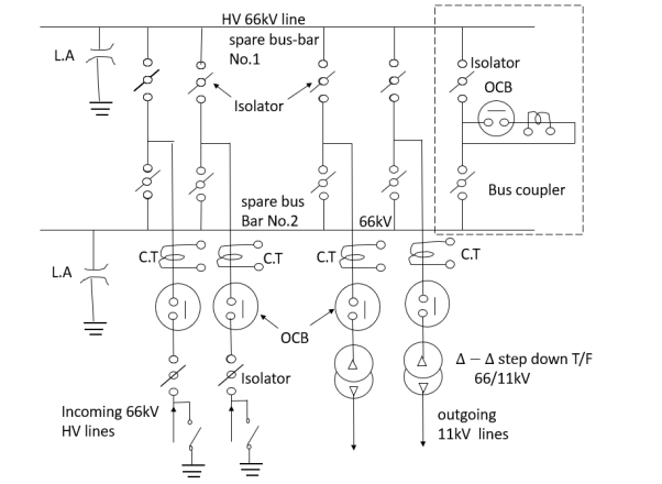
This type of bus bar is designed by combining the auxiliary type and the main bus bar by using a bus coupler to connect the circuit breaker and isolated switches. In case of overloading, the load is transferred from one to another bus bar by using a bus coupler. In this case, the potentials of the two bus bars should be the same to transfer the load and the main bar should be opened and should be kept closer to transfer the load.
HV lines of 66 kV can be connected to either of the bus bars through the bus coupler shown in the dotted line (The standard equipment like isolators, OCB, Earth switch, LA, T/F, CT, PT are connected as shown
Advantages:
- The main advantage is shifting the load from one type to another type if any fault occurs loss of continuity.
- The cost of repair and maintenance is less.
- Relays can be operated by using the bus potential.
- It is very easy to shift the load on any other buses.
Disadvantages:
- As the whole systems use two bus bars, the cost would increase.
- The whole system may breakdown if any fault occurs in any of the sections on the bus.
- To protect the operator and installation from electric leakage and to avoid electric shocks, the metallic parts of electrical installation are earthed by connecting it with the help a copper or G.I wire to earth. This is known as earthing.
- The earth wire from metallic parts is connected to the earth electrode which is buried underground systematically as per the I.S rules of electricity.
- Following simple sketch shows the earth wire connected to the electrode.
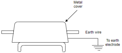
- The earth potential is zero. The earth wire and earth electrode’s resistance is very small and hence, leakage current passes to the earth quickly rather than to pass through the body of the operator as body resistance is very high in comparison with earthing system resistance and hence the operator is safeguard from leakage current shocks.
- Moreover, due to heavy leakage currents which passes through earthing system the fuses provided in the system immediately blow off and system as a whole is protected.
- So, earthing system safeguards the equipment’s as well as the operator and hence as per electricity rules the earthing is compulsory.
- In summer season, the soil becomes dry and this increase the earth resistance so to increase the earth resistance so to increase the moisture in the soil for better earthing, 3-4 buckets of water is poured in the tunnel provided at the top.
- The disadvantage of this system is that the fault, disconnection of earth wire and plate below the ground cannot be observed physically, hence repairing is costly.
International standard IEC 60364 distinguishes three families of earthing arrangements, using the two-letter codes TN, TT, and IT.
The first letter indicates the connection between earth and the power-supply equipment (generator or transformer):
T: Direct connection of a point with earth
I: No point is connected with earth (isolation), except via high impedance
The second letter indicates the connection between earth and the electrical device being supplied:
T: Direct connection with earth, independent of any other earth connection in the supply system
N: Connection to earth via the supply network.
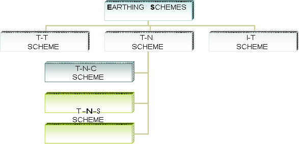
Earthing Schemes:
The earthing schemes are classified as shown in the following diagram.

TN Network:
In a TN earthing system, one of the points in the generator or transformer is connected with earth, "usually the star points in a three-phase system". The body of the electrical device is connected with earth via this earth connection at the transformer.
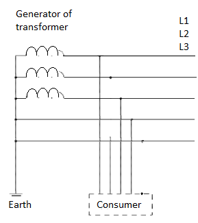
The conductor that connects the exposed metallic parts of the consumer is called protective earth (PE). The conductor that connects to the star point in a three-phase system, or that carries the return current in a single-phase system, is called neutral(N).
Three Variants of TN Systems:
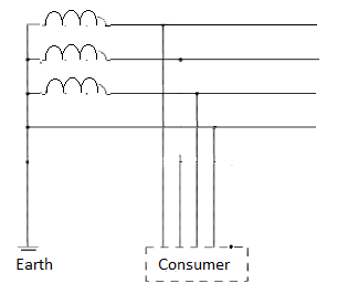
TN-S: PE and N are separate conductors that are connected together only near the power source.
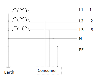
TN-S: separate protective earth (PE) and neutral (N) conductors from transformer to consuming device, which are not connected together at any point after the building distribution point.
TN-C: A combined PEN conductor gets the functions of both a PE and an N conductor.
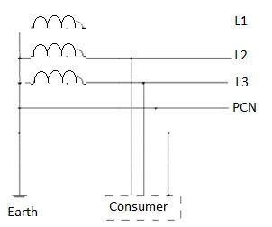
TN-C: combined PE and N conductor all the way from the transformer to the consuming device.
TN-C-S: Part of the system uses a combined PEN conductor, which is at some point split up into separate PE and N lines. The combined PEN conductor typically occurs between the substation and the entry point into the building, when the building separate PE&N conductors are used, this will reduce the risk of broken neutrals.
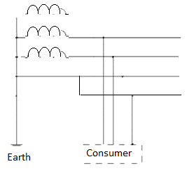
TN-C-S: combined PEN conductor from transformer to building distribution point, but separate PE and N conductors in fixed indoor wiring and flexible power cords.
It is possible to have both TN-S and TN-C-S supplies from the same transformer. For example, the sheaths on some underground cables corrode and stop providing good earth connections, and so homes where "bad earths" are found get converted to TN-C-S.
TT Network:
In a TT earthing system, the protective earth connection of the consumer is provided by a local connection to earth, independent of any earth connection at the generator.
Maintenance free earthing system:
1. Enhances earth conductivity & reduces earth resistance.
2. Ecological & prevents corrosion of earth electrodes (since no salt is used).
3. Maintenance free (1 pack of earthing gel may be applied per pit after every 5 years to maintain best soil condition).
4. Longer life of more than 20 years.
5. Terminals for direct earth termination to independent electrodes, though interconnected.
6. Earthing gel used is insoluble with water & stable up to 60 deg. C
7. Gel absorbs 15 times more water & hence offers least resistance
8. Space saving as compared to conventional earthing
9. Low earth resistance up to < 1 Ohm
10. Able to dissipate high fault/ leakage current instantly.
Significance of Good Earthing
1. Electric shock prevention.
2. Grounds leakage current/ lightening energy & prevents accidents & other hazards
3. Ensures that all exposed conductive parts don’t attain dangerous potential
4. Equipment’s work effectively without failure, as reference voltage is near to zero
5. Provides balanced 3 phase voltage
6. Helps increasing life of motor, electronic cards and other equipment
7. Efficiency of equipment increases due to balanced electrical circuit & reduced leakage current
8. To avoid frequent tripping of the overload relays, setting of motor relay is kept higher than actually required. Many a times motors can’t withstand this high current for long & burns out. This high current flows through relays/ contactors/ cables etc. resulting in failure of the same. Proper & good earthing avoid these kinds of instances.
i) Fall of potential methods:
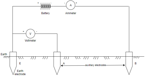
A source of current (battery) is connected between earth electrode ‘E’ and auxiliary electrode B. The auxiliary electrode ‘B’ which is usually an iron spike is inserted in earth at a distance away from the earth electrode. The current is passed through earth electrode E to an auxiliary electrode B. Second auxiliary electrode A is inserted in earth between E and B. The voltage between E and A is measured for a given current ‘I’. The resistance of earth is given by

The position of E and B is fixed and the position of electrode ‘A’ is changed and resistance measurement are done for various position of electrode ‘A’. The nature of graph plotted between earth resistance against distance between E and Ai.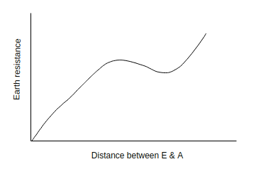
Initially the earth resistance rises rapidly, it then becomes constant and when the auxiliary electrode approaches electrode B, the resistance rises again. Hence placing of electrodes plays an important role. The flat portion of graph gives value of earth resistance  .
.
Ii) Earth tester:
The earth tester is special type of megger and it has some modifications in comparison to megger.
- Rotating current reverser
- Rectifier
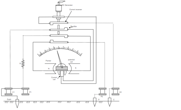
Both these additional features consist of simple commutators made up of ‘L’ shaped segments. They are mounted on the shaft of generator.
The earth tester has four terminals P1, P2 and C1, C2. Two terminals P1 and C1 are shorted to form a common point to be connected to earth electrode (E). The other two terminals P2 and C2 are connected to auxiliary electrodes P and C respectively.
The indication of the earth tester depends upon the ratio of the voltage across the pressure coil and current through the coil. The deflection of its pointer indicates the resistance of earth directly.
Iii) Earth Loop tester:
An earth loop tester is just an ohm meter, operated either by a.c. or d.c the test. Probs are connected between the earthing point under test and neutral conductor of the supply mains. Earth loop tester is connected for testing the earth pin of three pin plug.
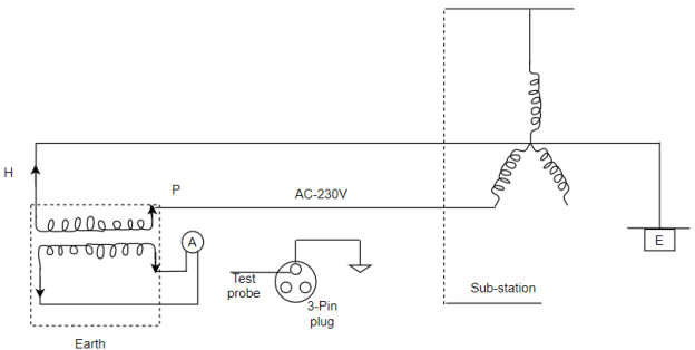
This method of earthing gives the total resistance of entire loop comprising the sub-station earth electrode, consumers earth electrode and all earthing leads.
1.Plate Earthing:
A copper or galvanized plate is used as electrode of earthing purpose, standard size of plate recommended.
For copper plate:  thick
thick
For G.I plate: thick
thick
Copper plate is very rarely used.
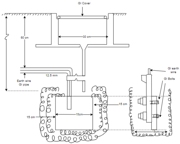
The G.I plate is kept vertically at a depth of 3m. It is embedded in coke layers of 15 cm around it to this the earth resistance decreases. The nut bolts used are G.I for the G.I plate.
The earth wire is bolted to the earth plate with nut, bolt and washer.
The nut bolts are also of G.I for G.I plate and if copper plate is used, then the earth wire, nut, bolts and washer should also be of copper.
2.Pipe Earthing:
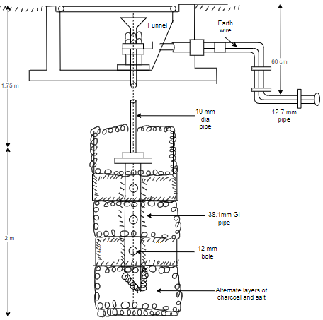
The G.I pipe of 38.1 mm in diameter and 2m long is used for this type of earthing. If the soil is rocky and dry, then the pipe length taken is 2,75m.
The pipe is placed vertically upright. The depth of pipe should be 4.75 m.
If the soil is wet, then the depth can be less than this alternate layer of charcoal and salt is provided 15cm around the pipe. This decreases the earth resistance.
The earth wire used must be G.I wire (not of copper) as the G.I pipe is used. The earth wire 19mm diameter is taken out through a 12.7mm diameter pipe, 60cm below the ground.
We can pour water whenever required to increase the wetness (moistures). This decrease the resistance and earthing is improved.
Tolerable step voltage:
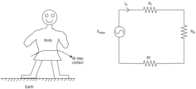
Figure shows the body of a person standing ground with separation of his feet by 1 meter the current through body is  and body resistance is
  .
.
The potential difference shunted by the body is limited to the maximum value between two accessible points, on the ground surface, separated by one space (assume ).
).
 is the earthing resistance of one foot in Ω.
 is the body resistance in Ω.
- Tolerate step voltage
 by referring to circuit diagram is given by
Tolerable touch voltage:
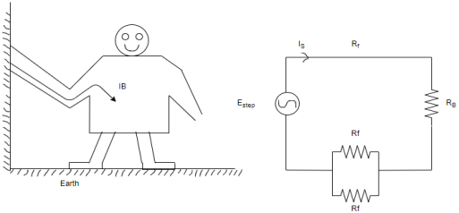
The maximum earth potential difference intercepted would be that which would occur over a distance along the ground equal to the maximum permissible possible horizontal reach.
Tolerable value of touch potential is,

 If,
If,  Ω
Ω
-  is resistivity of soil
99.5% of person of 50 kg weight can safely with stand the current of 0.116/  where ‘t’ is seconds.
Then,

 volts
volts


 volts
volts
● Step potential: The potential difference shunted by a human body between two accessible points on the ground separated by the distance of one space assumed to be equal to one meter.
Touch potential: The potential difference between a pint on the ground and a point on an object likely to carry fault current (e.g., frame of equipment and which can be touched by a person).
Steps involved in design of earthing grid:
i) Earth fault current: The maximum earth fault current constructs a major factor in the earthing system design this determines the cross section of the earthing system potential. The potential gradients are also a function of this current. It is common to consider the symmetrical value of the maximum single line to ground fault.
Ii) Soil Resistivity: The Resistivity of earth varies within extremely wide limits between 1 and 10000 . To design the most economical earthing system for a substation it is necessary to obtain accurate data on the soil resistivity and its variation of the station site. Even of the soil may vary considerably at different times of the year. It is therefore necessary that the measurement is made a number of times during different parts of the year. A number of test location should be chosen at each side to cover a wide area of the soil.
Iii) Fault clearing time: There are many considerations which influence the choice of fault clearing time such as the system stability, the type of switchgear and relaying used. The short time rating of switchgear as per Indian practice is based on 3 seconds. Therefore, 3 seconds time may be adopted as the fault clearing time for earthing calculations. However, the system design engineer has to use his judgement to adopt any lower value consistent with the operating times of circuit breaker and relays used on the system (0.5 to 1.5sec).
Iv) Area covered by sub-station: The area covered by the substation is governed by the number and types of equipment. After the layout has been decided and substation plan finalized it is a simpler matter to calculate the area covered by the substation. The next steps in the design procedure are Selection of earthing material.
v) Determination of size of earthing conductor.
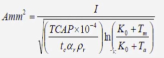

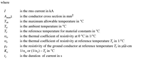
Vi) Preliminary arrangement of earthing conductors
Vii) Determination of conductor length required.
Viii) Calculation of resistance of earthing system.
Ix) Checking of design for various voltages.
References:
- P.S. Pabla –Electric Power Distribution, 5th edition, Tata McGraw Hill.
- S. L. Uppal, Electrical Wiring and Costing Estimation, Khanna Publishers, New Delhi.
- Surjit Singh, Electrical wiring, Estimation and Costing, Dhanpat Rai and company, New Delhi.
- Raina K.B. And Bhattacharya S.K., Electrical Design, Estimating and Costing, Tata McGraw Hill, New Delhi
- B.D. Arora-Electrical Wiring, Estimation and Costing- New Heights, New Delhi.
- M.V. Deshpande, Elements of Power Station design and practice, Wheelers Publication.
- S. Sivanagaraju and S. Satyanarayana, Electric Power Transmission and Distribution, Pearson Publication.