Unit - 3
Maintenance and Condition Monitoring
1) In order to increase the life of the machine and to keep it working satisfactorily, its maintenance is very important.
2) Maintenance work is to take care of the machine to obtain the satisfactory results from it.
3) Maintenance work is carried out to prevent the damage, obstacles and breakdown of the machine.
4) Maintenance prevents the ill effect in future.
5) The main objective of the preventive maintenance is to protect the insulation and to maintain it in good condition to increase the life of the machine.
6) Particularly in Electrical, where the machines are of rotating type and stationary type and which operate on or deals with higher voltages, are to be given due importance.
7) The insulation starts deteriorating due to the absorption of moisture (present in the surroundings) dirt, and dust a large amount of heat produced in the machine due to losses etc.
8) The periodic attention is therefore essential to remove moisture dirt, dust and keep the machine cool by carrying away the heat produced.
9) A panned and rigid system of periodic inspection and preventive maintenance
Will ensure undisturbed trouble-free service and prolong the life of the equipment.
10) Maintenance includes periodic and regular inspection, testing and reconditioning faulty parts etc.
11) The maintenance schedule depends on the type of the machinery, frequency of its use, climatic and environmental conditions, service use of the conductor and the machines load cycles.
12) If the due care is not taken then different types of faults may occur frequently.
Advantages of Maintenance:
1) Increases profitable uptime
2) Minimizes the machine's failure
3) Improves performance
4) Improves system reliability
5) Saves money on energy requirements
6) Save time
7) Increase plant capacity
8) Increases the ease of operation of the machine
9) Increase the machine's safety
10) Increase operator’s safety
Maintenance –
1) Routine Maintenance
2) Preventive Maintenance
3) Breakdown Maintenance (Corrective)
4) Planned Maintenance (Scheduled)
5) Condition-based Maintenance (Predictive)
1) Routine Maintenance: This kind of maintenance is a routine work i.e., daily work so routine maintenance is the overall daily maintenance of the machine.
After the stoppage of the machine on the earlier day, the next day the machine is to be neatly cleaned to remove dirt, dust near wastages scraps.
For cleaning, a soft cloth broom or a vacuum cleaner blower may be used.
Checking the switch starters indications neatly before starting the machine.
In daily routine work current, voltage, power may be periodically observed or noted and a record may be kept for a certain purpose.
Earth connection must be checked to avoid shocks from leakage current.
While the machine is working thermal conditions must be ascertained by checking temperature. Excessive temperature may damage the equipment insulation.
For mechanical stability of the machine, it is ensured that the working is noiseless, vibration less.
So routine maintenance is to check daily- the electrical and mechanical stable conditions.
2) Preventive Maintenance:
i) Preventive maintenance can be done by, conducting the different test, measurement replacement of parts, adjustments etc.
Ii) In order to ensure that major faults do not develop in the future and to prevent burning out damages, breakdowns etc., due care is given by preparing a planned schedule of maintenance which can be called as preventive maintenance schedule.
Iii) For different machines like the rotating machines and static machine (transformer) the maintenance schedule chore are prepared.
Iv) These charts are displayed and the maintenance schedule is exercised and followed.
Basic aspects of preventive maintenance:
- Inspection – what to inspect, how to inspect?
- Frequencies – How often to inspect?
- Schedule – when to inspect?
- Organization – who to inspect?
- Record keeping – what to record? How to record
The following points are firstly considered prior to a final preventive maintenance schedule.
i) Too frequent inspection – will be a waste of time and will not be economical.
Ii) Too less frequency will invite failure of operation the machine and disturbance in the continuity of operation.
Iii) So, during the frequency of inspection schedule, the following points are taken into consideration:
Age of the machine- Several days, months years of working the machine, its parts become incapable to give good service. It may become too costly to frequently repair these parts. Think of replacing the parts / replacing the machine. Also replace outdated the machine and bring latest the machine in the service.
Duty Cycle: The frequency of inspection Schedule depends on the duty cycle working of the machine. There are different frequencies for the different duty cycles such as continuous working, Intermittent working, very less period working.
Cost of the machine: If machine is too costly, then utmost care is to be taken and hence in its case inspections are frequent. In case of moderate and low-cost machines frequent inspections are not recommended.
Overload working of the machine: In such conditions, the inspections of temperature rise must be the frequent, cooling system must be taken care of by frequent inspection or the Air circulation ventilation must be taken care of.
3) Breakdown Maintenance: (Corrective)
As the name suggests this maintenance is essential in case of failure of activity /breakdown in the operation of the machinery.
Failure of the machine may take place due to serious electrical or mechanical faults.
Electrical faults may be due to short circuit, overheating, failure of insulation earth fault etc.
Mechanical faults may be due to damages of ports, bearing jamming, failure of cooling system, clogging ventilating ducts, much more deviation in the air – between rotating and static parts losing of stamping of an iron core, etc.
After such happenings, the machine is completely shut down and is to be taken for inspection fault finding and repairs. This is done so that continuity of work can be brought back in a shorter period to avoid further shutdowns
To avoid such happenings ensure that: a) Insulation is in tack (If not make necessary replacements) b) see force motion of routing parts c) check uniform air gaps between static and rotating gears d) Tighten the loose bolts nuts parts terminals etc. e) Air circulation system and cooling system should be repaired.
4) Placed maintenance (Scheduled Maintenance):
The Placed or Scheduled maintenance is carried out to a predetermined interval of time.
If neglected, it can result in a breakdown of equipment.
This maintenance is performed purposely and regularly in order to prevent a machine from breaking down.
Generally scheduled maintenance is followed by
- Overhunting of the machine (Inspection)
- Repairs, Cleaning of water & other tanks
5) Predictive or condition-based maintenance:
Maintenance performed based on known and expected behavior condition and the history of the machine is called as condition-based maintenance.
This maintenance is performed after one or more show that the equipment is going fail or when the performance of the equipment is deteriorating.
Condition-based maintenance was introduced to try to maintain the correct equipment at the right time.
By observing the state of the system known as “condition monitoring” this maintenance is performed.
Advantages:
i) Better product quality
Ii) The decrease in the process downtime
Iii) Improves worker and environmental safety
Iv) Improves workers morale
v) About 10% cost saving over preventive maintenance program
Vi) Increase component operational life
Vii) The decrease in costs for parts & labor
Disadvantages:
i) Increased investment in staff training
Ii) It increases investments in diagnostic equipment.
Iii) Saving potentials are not readily seen by management
Factors affecting Preventive Maintenance:
Considering the study of machine, cost of the machine, use of the machine, type of rating of machine i.e., continuous rating, intermittent rating etc. the maintenance schedule is prepared.
But there are core causes and situations in which the schedule cannot be followed due to the following factors:
i) Position of Machine in the plant:
There are various machine positions in the plants as per the sequence of operations and availability. In certain cases of machine, it is also possible due to constraints of space, the experts face difficulties in carrying out inspection /maintenance work. This factor affects maintenance schedule.
Ii) Age of the Machine:
Due to continuous running for several days /weeks months /Years, the parts are worn out and cannot be repaired and they cannot be maintained thereafter, which affects the main schedule. Replacement is the solution.
Iii) New technology in Machine:
The previous machine may be such that they run for more periods for the same work. The work can be completed with good quality within a short period of time by installing the new and latest technology in the machine. Hence, replacement is required and maintenance is charged for new machine.
Iv) Working Condition of the industry:
The industries are run to get more and more profit and hence sometimes accept heavy orders of manufacturing. To meet this order in a shorter time, the plant runs for longer hours. Hence Maintenance schedule is disturbed more emphasis is towards production rather than the schedule maintenance
v) Periodic orders:
Some industries have orders of production in a particular period of a month or a particular period in a year and in the rest of the periods there is little work or no work on the Machine. This ideal period is chosen for maintenance. This affects the regular maintenance schedule.
Vi) Unforeseen cause: due to accidents or fires, the workers are stuck, the work is holding up for a certain period. This is also a cause of disturbing maintenance schedule
Vii) Strategy of new management in industry: Sometimes the management is changed in the industry some sections have to be shut off and some sections have to be overloaded as per the new management decision. This also changes the maintenance Schedule
Viii) Failure of Machine: This point also affects the normal maintenance schedule.
Summarizing the points, the preventive maintenance schedule is affected due
Access to rescue machine
Mode of operation
Management decision
Unforeseen causes
Working not consistent
Failure of Machine
Replacement of Machine
i) Daily maintenance:
Examine visually earth connections and motor leads
Check motor winding for overheating.
Examine control equipment
In case of oil lubricated motors, examine bearings to see that oil rings are working and note the temperature of bearing
Ii) Weekly Maintenance:
Check belt tension in cases where this is excessive it should immediately be reduced
Blow out winding of protected type motors situation in a dusty location.
Examine starting equipment for a burnt contact where the motor is started and stopped frequently.
Examining oil in the case of oil ring lubricate bearings for contamination by dust. Grit etc. (This be roughly judged from the color of the oil)
Iii) Monthly maintenance:
Overhaul contractor
Inspect and clean oil
Renew oil in high-speed bearing in a dusty location.
Wipe brush holders and check bedding of brushes of slip – ring motors.
Iv) Half – Yearly Maintenance:
The windings of motors are subjected to corrosive or other elements, so cleaning is required and varnish if necessary
In case of slip –ring motors check slip – ring for grooving or unusual wear
Check grease in ball and roller bearings and make it up where it necessary taking care to avoid overfilling
Drain all oil-bearing wash with petrol to which a few drops of oil have been added.
v) Annual Maintenance:
Check a high-speed bearing and renew it if necessary.
Blow out a motor winding thoroughly with clean dry air. Make sure that the pressure is not high as to damage insulation.
Clean & varnish dirty & oily winding.
Check overworked motors which have been subjected to severe operating conditions.
Renew switch and fuse contacts if damaged.
Check the oil: Renew oil starters subjected to damp elements.
Check insulation resistance to earth and between the phase of motor winding control gear & wiring
Check resistance or earth connection
Check air gaps.
Vi) Records:
Maintain a register giving one or more pages for each motor and record there in as important inspections & maintenance work carried out from time to time. These records should include past performance, normal insulation level, air measurement nature of repairs and time taken for previous repairs and other important information which would be helpful for good performance maintenance.
Preventive Maintenance of Induction motor:
i) Provide adequate ventilation.
Ii) Lubricate oil as per schedule
Iii) Keep machine and the area around machine clean & dry
Iv) Observe the change in motors operating condition
v) Keeping records of the maintenance check of machine
Vi) Attend minor repairs before major repairs to faced
Vii) Measuring electrical characteristics of motor comparing them overtime to any changes.
Activities in the preventive maintenance of motors.
Sr. No | Activities | Daily | Weekly | Monthly | Half-yearly | Yearly | Five yearly |
1 | Visual Inspection | √ |
|
|
|
|
|
2 | Cleaning blowing |
| √ |
|
|
|
|
3 | Choking back –gears |
|
| √ |
|
|
|
4 | Slip – rings of motor |
|
| √ |
|
|
|
5 | Air – gap checking |
|
|
|
| √ |
|
6 | Bearing checking |
|
|
| √ |
|
|
7 | Measurement Ins resistance |
|
|
|
| √ |
|
8 | Cheak all nut –bolt fitting |
|
|
| √ |
|
|
9 | Vibration checking |
|
|
| √ |
|
|
10 | Starrer /Controller |
|
|
| √ |
|
|
11 | Bearing Maintenance |
|
|
| √ |
|
|
12 | Cooling System |
|
|
|
| √ |
|
13 | Overhunting |
|
|
|
|
| √ |
The maintenance schedule for synchronous machine (Alternators)
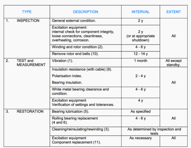
Maintenance Schedule for transformer 100KVA & above
Monthly Basis Maintenance of Transformer
The oil level in oil cap under silica gel breather must be checked in a one-month interval. If it is found the transformer, oil inside the cup comes below the specified level, oil to be top up as per specified level.
Breathing holes in silica gel breather should also be checked monthly and properly cleaned if required, for proper breathing action.
If the transformer has oil filled bushing the oil level of transformer oil inside the bushing must be visually checked in the oil gage attached to those bushing. This action also to be done monthly basis
If it is required, the oil to be filled in the bushing upto correct level. Oil filling to be done under shutdown condition.
Daily Basis Maintenance and Checking
There are three main things which to be checked on a power transformer on a daily basis:
Reading of MOG (Magnetic Oil Gauge) of main tank and conservator tank.
Color of silica gel in breather.
Leakage of oil from any point of a transformer.
In case of unsatisfactory oil level in the MOG, oil to be filled in transformer and also the transformer tank to be checked for oil leakage. If oil leakage is found take required action to plug the leakage. If silica gel becomes pinkish, it should be replaced.
Yearly Basis Transformer Maintenance Schedule
The auto, remote, manual function of cooling system that means, oil pumps, air fans, and other items engaged in cooling system of transformer, along with their control circuit to be checked in the interval of one year. In the case of trouble, investigate control circuit and physical condition of pumps and fans.
All the bushings of the transformer to be cleaned by soft cotton cloths yearly. During cleaning the bushing should be checked for cracking.
Oil condition of OLTC to be examined in every year. For that, oil sample to be taken from drain valve of divertor tank, and this collected oil sample to be tested for dielectric strength (BDV) and moisture content (PPM). If BDV is low and PPM for moisture is found high compared to recommended values, the oil inside the OLTC to be replaced or filtered.
Mechanical inspection of Buchholz relays to be carried out on yearly basis.
All marshalling boxes to be cleaned from inside at least once in a year. All illumination, space heaters, to be checked whether they are functioning properly or not. If not, required maintenance action to be taken. All the terminal connections of control and relay wiring to be checked an tighten at least once in a year.
All the relays, alarms and control switches along with their circuit, in R&C panel (Relay and Control Panel) and RTCC (Remote Tap Changer Control Panel) to be cleaned by appropriate cleaning agent.
The pockets for OTI, WTI (Oil Temperature Indicator & Winding Temperature Indicator) on the transformer top cover to be checked and if required oil to be replenished.
The proper function of Pressure Release Device and Buchholz relay must be checked annually. For that, trip contacts and alarm contacts of the said devices are shorted by a small piece of wire, and observe whether the concerned relays in remote panel are properly working or not.
Insulation resistance and polarization index of transformer must be checked with battery operated megger of 5 KV range.
Resistive value of earth connection and riser must be measured annually with clamp on earth resistance meter.
DGA or Dissolve Gas Analysis of transformer Oil should be performed, annually for 132 KV transformer, once in 2 years for the transformer below 132 KV transformer and in 2 years interval for the transformer above 132 KV transformer.
Maintenance of Transformer on Half Yearly Basis
The transformer oil must be checked half yearly basis that means once in 6 months, for dielectric strength, water content, acidity, sludge content, flash point, DDA, IFT, resistivity for transformer oil.
In the case of a distribution transformer, as they are operating light load condition all the time of day remaining peak hours, so there is no maintenance required.
Routine Preventive Maintenance of Transformer:
A) This Includes:
Over a Visual inspection without dissenting
Checking oil level through a glass window in conservator tank cooling system
Leakage brushing conservator
Breather silica gel color.
B) Following test are performed:
Measurement of insulation resistance
Tranformer oil breakdown voltage test
Gas sample from Buchholz relay
C) Mechanical Maintenance:
Tighter of fittings Due – bo Hs
Oil deposits, dust deposits
Silica gel removal if color is observed to be changed from blue to pink
To make up oil level in a tank by adding oil
D) Periodic Maintenance:
This includes the following test
i) Dilemmatic test
ii) Acidity Test
iii) Crackle Test
iv) moisture contain.
1) Electrical Stresses: The insulation is designed for a particular application. Overvoltage & under voltage causes abnormal stress with the insulation which can lead to the cracking or degradation of insulation. During lightening heavy impulse surge voltage can come across the insulation materials. Even switching produces voltage surges. Such transient voltage when greater than the breakdown voltage of insulation breaks the insulation material and the insulation material loses the insulation property.
So, for electrical stress can the given by formula Life 
E = voltage level n = constant value which varies from
2) Mechanical Stress: The Mechanical damage such as lifting or while digging. The Mechanical stress also assures running a machine out of blend for frequent start & stops. The resulting virus from machine operation may cause defects with the insulation. It develops very small craws in the insulating material. Hence reduce the life of insulation.
3) Thermal Stress: The heat is produced in the insulating material due to dielectric loss. Copper loss takes place in the conductor. The heat produced by copper loss in the conductor is also by nearby insulating material. If sufficient and proper ventilation and cooling is not provided then the insulating material loses its thermal stability which reduces the life of insulating material and thermal stability, which means the heat devoted in the insulating material should be equal to heat thrown out by the insulating material.
4) Absorption of Moisture: The absorption of moisture by insulating material decreases its surface resistance. It causes insulation failure or breakdown. The moisture affects the mechanical strength of insulating material.
5) Temperature: The insulation resistance decreases with temperature. The diction loss increases with temperature. The resistivity of the insulation material decreases by an increase in temperature
6) Deposition of dust dirt, oil: The surrounding atmosphere contains dust particles. These are accumulated over the electric machine and the dirt reduces the insulation resistance thus insulation becomes weak.
7) Impurities: Impurities present in the insulating material reduces the insulation resistance as well as the dielectric.
Insulation:
Insulating materials offer very high resistance to the flow of current. They have the resistivity of the order of 1012 Ωm. The heating element electrical iron is sand witched between mica sheet. The transformer tank is filled with mineral oil. The wires are coated with PVC insulation. The function of insulating material is to insulate live parts. The insulating materials exists in three:
Solid Insulation – wood, paper, plastic, mica, Bakelite, porcelain, asbestos
Liquid Insulation: Varnish mineral oil petroleum oils. Hydrocarbons
Gaseous Insulation – Air, SF6, Nitrogen, Neon, H2, CO2
1) Insulations fail due to moisture absorption.
2) Also due to impurities in the insulating material, some proportion of insulation deteriorates after some period of use.
3) Air pockets in the insulation also are the cause of insulation failure
Failure of gaseous insulation:
Due to humidity
Pressure
Failure of liquid Insulation (Transformer, oil):
The insulation gets disturbed when the following impurities are present as
Water
Dirt dust
Carbon Deposits
Sulphur
Acids
Gases
Grease
Alcohols
Acetone &
Ketones
Presence of sludge which is mainly an oxidation product whose formation is accelerated by temperature & contact with air.
Measurement of Insulation Resistance (Megger)
1) Megger tests are simple, useful common widely used non-destructive widely used insulation solid insulating components, subassembly complete equipment, and complete plant.
2) The insulation resistance test is applied before the first voltage endearing of the equipment during routine maintenance and after repair before decommissioning
3) Megger test is applied before and often high voltage high power teat
4) Insulation resistance Measurement is cortile by means of a portable Megger
5) Dielectric absorption ratio (DAR) test Polarization Index (PI) tests are also carried out by means a megger
6) Megger has a mega meter a built-in DC generator
7) The Scale of a megger is graduated from zero mega- ohm infinity
8) The rotor of a DC generator of a megger is h, and or motor-driven
9) Megger is a portable Dc insulation tester with a build-in dc generator having. Permanent magnet and h, and driven rotor mega ohm meter current coil and potential coil
10) Mega ohm meter graduated in terms of mega –ohms (0 to 00)
11) The mega ohm meter reads R = V/I
- Zero megger readings indicate the short circuit or failed insulation
- Low megger reading indicates high current & poor insulation
- High megger reading on the outsets suggest insulation is generally good but more forth high voltage tests are generous good but further high voltage tests may be necessary to confirm with gl and capability
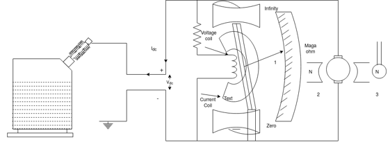
1- Mega ohm meter
2 – Dc Generator
3 – Test object
Rated voltage ckt. Under test | 220 v | 440 v | 1000V | 3. 3 & |
Test Voltage for InR test | 500 V | 1000v | 2. 5 kv | 5 |
The DA Test, or Dielectric Absorption Ratio (DAR), is the ratio of the megohms at 1 minute divided by the megohms at 30 seconds.
DAN = 
A DAN rating below 1.25 is a cause for investigating and possible repair of the electric apparatus.
Polarization Index test is a specialized application of the dielectric absorption test the polarization index is the ratio of the insulation resistance at 10 min. To the insulation resistance of 1 min on the application of continuous test VOLTAGE.
Polarization Index = 
A polarization index of less than 1 indicates equipment deterioration & the need for immediate maintenance and that the equipment should not be energized.
This test is for dry insulation systems such as dry transformer cables, rotating machines, etc.
Motor-driven megger is necessary InR – 10 is more than InR – 1 because competitive charge current is initially high and Inr = 
 = Component due to poor insulation & leakage Current
 = Capacitive charging current
 In Rl0 =
  as Ic = 0 at t = 10min
 InR 10 is more than In R1
1) Condition Monitoring of the machinery is the mean source of various parameters related to the mechanical condition of the machinery such as bearing term oil pressure. Vibration and performance tests which make it possible to determine whether the machinery is in good condition bad condition or medium condition.
2) Say if the machinery is in bad condition, then condition monitoring makes it possible to determine the cause of the problem.
3) Condition Monitoring is the major component of predictive maintenance.
4) The use of condition monitoring allows maintenance to be Schedule or other actions to be taken to avoid the consequences of failure before and also determine whether the item equipment is in serviceable condition
5) Condition monitoring in valves online measurement of several parameters relates to operating stresses aging & control which together help to diagnose the condition equipment.
Purpose:
1) To reduce cost with improved equipment utilization
2) To improve the reliability of power supply by reducing or eliminating force outage.
3) To extend the life of equipment with optimal loading.
4) To optimize cost i.e., to move from periodic or preventive maintenance to a condition-based (Predictive) maintenance.
5) To prevent sudden / Widespread failures that can result in costly and delayed remedial action and affect the safety to personas & environment
6) Residue’s life assessment to take investments to take invest marts decisions for replacement
7) Reliable Failure analysis that helps to improve the design of the equipment & the system
Benefits:
A) For the equipment:
Extends life of equipment
Use of equipment for maximum economical efficiency becomes possible.
Minimizes the severity of any damage & eliminates consequential repairs hence helps in the overall economy of plan
A volt’s destruction of peripheral equipment
B) Failures / Faults:
Confirmation of the presence of fault is done
Become possible to take protective steps immediately to avoid failure.
C) Maintenance strategies:
Preventive maintenance affected immediately
Predictable and reliable Maintenance schedule planned
Timely filed measurements were done
Reduction in maintenance is possible
D) Other Benefits:
Increment in system stability
Reduction of up – planned outage
Prevention of sudden failure
Minimizes severely accidents
Increases safe working environment
Future planning and uprating
Easier (safe)
Sr. No | Tools/Techniques | Application | Fault/ The machine |
1 | Scan angesis | Analysis of non-stationary signal | Fast runup /do
|
2 | Zoom | Separation of closely speed com proven Improvement of signal to noise ratio | Electrical Machine turbine general |
3 | Phase Balancing | The direction of developing a crack in shafts | Rotating the machinery |
4 | Time Signal | To. Identify distortion by waveform visualization | Cracked tec rubbing clipping |
5 | Dynamic arrest factor | Calculation of high pass filtered signal | Faults in low-speed Machine |
6 | Synchronous time averaging | Improving the signal to the noise level. Separating electrically & mech induced vibrations Separating effects of advancement Machine | Elle Machine gearbox reciprocating Machine |
7 | Impact testing | Resonance testing | Gears Found tic coupling |
8 | Envelop analysis | Amplitude demodulation objection of allow frequency amplitudes modulations happening at high frequency | E/e Machine gear Boxes Bearing |
- Failure due to structural defects:
Improper tightening of core bolts or clamps resulting in excessive vibrations of laminations and weakness of core insulation.
Improper solder joints and loose connections in the structural parts resulting in overheating and carbonization of oil.
Leaks in the tank causing oil leakage resulting in overheating and subsequent failure in the used gascates.
Blocking of cooling tubes result in reduced law of cooling medium and it is a result of overheating.
2. Failure due to over fluxing:
Flux density directly proportional to voltage and inversely proportional to supply frequency.
At higher flux density the core gets saturated and flux then passes through the core bolts.
The core bolts get heated resulting in the melting of core bolts and burning of core Bolt lamination.
Over fluxing relay generally provided for the protection of transformer to sustain higher voltage on the primary side of transformer.
3. Failure in insulation:
Moisture entering in oil at the time of breathing.
Deterioration of oil due to partial discharge.
Puncture in insulation.
Inadequate cooling ducts.
Fall of oil level.
4. Failure in the winding circuit:
Open circuit in the winding
Short circuit in the winding
Inter turn failure
Improper transportation
Heavy prolonged overload.
Thermal aging of winding due to short circuit.
Expansion and contraction of winding due to variation in load.
5. Failure due to cooling system:
Stoppage in the cooling medium due to failure in an auxiliary cooling plant.
The high temperature of water-cooled transformer this may be due to cooling tubes blocked due to deposits of lime matter reducing water supply.
Water-cooled transformer failure, due to leakage of water into the oil.
Moisture in oil of water-cooled transformer. This is due to condensed moisture on water pipes entering the oil.
6. Failure in the magnetic circuit:
It is nothing but failure of following components:
- Yoke, core, clamping structure
- Core Bolt failure
- Lamination insulation failure, local heating due to short circuit between laminating.
- Abnormal air gaps between joints of core and yoke.
- High inrush current
- Vibration in the core.
Characteristics of transformer oil:
The properties of transformer oil and switchgear oil are recommended in IS 335-1963.
The fresh dielectric oil has to be clear yellow color, dark color or cloudy appearance. Impurities have a bad effect on the properties of the oil.
The dielectric oil should never contain suspended particles, water-soluble acids, and bases, active sulphur or colloidal carbon.
these impurities accelerate deterioration of the insulating properties of the dielectric oil resulting in an internal flashover.
the dust particles, carbon particles, and sludge in the oil which is in the suspended form in the oil gather along the conductor and insulator surfaces in presence of electric field.
Thereby a thin conducting layer is formed gradually along with the internal insulation during service.
The flashover can occur along the surface of the insulation of the tank due to cracking.
Dust and other particles are removed by means of filters in the oil filtering unit.
Moisture in oil lowers the dielectric strength thereby causing internal flashover. Moisture is introduced in the circuit breaker through defective seals.
Sometimes oil fields in the breakaway itself have higher moisture content.
During the periodic maintenance, the moisture is reduced from say 30 parts per million to below 5 parts per million by filtering the same.
Viscosity indicates fluidity oil with low viscosity has more fluidity and gives better cooling.
At lower ambient temperature the viscosity sharply rises and the speed of the oil circulation reduces. Hence viscosity should be measured at various temperatures and the characteristics of contact travel should be plotted at various temperatures.
A higher flashpoint is preferred. Flashpoint indicates a tendency to evaporate. For flashpoint lower than 135 degrees Celsius the oil tends to evaporate rapidly, thereby the viscosity rises and the total volume of oil reduces.
Testing of transformer oil:
The transformer oil should be checked during periodic maintenance.
The moisture and dielectric strength are major, if necessary, oil should be filtered.
The oil sample is taken in a standard oil test cell [80×60mm cross-section area 100mm height]
Electrodes are polished brass spares mounted horizontally. The gap spacing is 6mm± 0.02mm.
A sample of insulation oil is taken from the bottom of the tank.
It is tested by means of portable oil testing which consists of a transformer volume tripping device etc.
The voltage can be gradually increased.
Oil in good condition should withstand 5KV r.m.s. For one minute in a standard testing Cup with a 6mm gap between electrodes.
A gap of 2.5 millimeters should have break down value above 45 kilovolt.
The oil should be tested during the periodic check and whenever the circuit breaker clears the fault.
Preferred minimum BDV (Breakdown Voltage) of Transformer oil
Oil samples | Upto 11 | 11-33 | 66-220 | 220 |
Fresh oil from a drum | 25 | 30 | 40 | 45 |
Used oil from Transformer | 20 | 25 | 35 | 40 |
Contamination of Oil due to moisture of solids can be dealt satisfactorily at sight. Centrifugal separators are effective in removing free water and find solid impurities.
Properties of Transformer oil
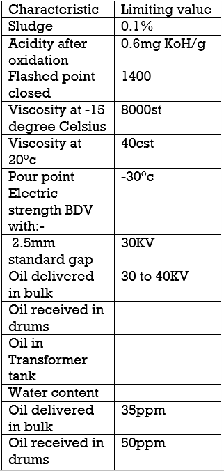
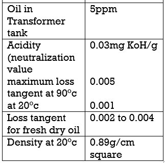
Flashpoint test:
In this test the transformer oil is heated continuously till a point is reached at which the vapor is formed on the surface of oil fires simultaneously. The temperature of the oil at this point should not be less than 130°C to 140°C.
Crackle test:
The objective of this test is to determine the presence of water or moisture in the oil. In this test sample of transformer oil under test is taken in a test tube. It is heated on a gas burner, if water or moisture is present in the oil, cracking noise is heard.
Another method, sample of oil taken in the glass beaker of 250 ml. An iron rod of 12.5 sizes is heated to red hot and then plugged into oil under test if a cracking noise is hearing it indicates the presence of moisture in oil.
This is done to remove all contaminations such as water, carbon deposits, dost, sludge dissolved moisture, and gases so that the dielectric strength of oil increases, also other properties are improved and oil again becomes usable safely.
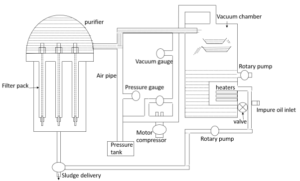
The following parts are mentioned below:
- Oil inlet pipe
- Heaters
- Fitter packs
- Motor
- Pure oil outlet
- Heating chamber
- Purifier chamber
- Vacuum tank
- Pump
- Sludge outlet
Through the inlet pipe, the oil is taken in the heating chamber.
In this chamber heater units are provided by which the oil is heated to a temperature of 60°c to 75°c.
the advantage of heating is to make the oil thinner which facilitates separation of impurities moreover to release dissolved gases and moisture.
the hot oil is pumped into the purifier chamber in this chamber the oil is pressed under high-pressure point pressure is about 6kg/cm square.
The oil then passes through several stocks of special prepared thin paper discs which are kept tightly packed and compressed by powerful springs.
the interfaces between the surface of the filter paper are so fine that even microscopic impurities cannot pass through.
All such impurities are accumulated on the outer surface of the filter packs.
The purified oil is withdrawn from the central holes in the papers track through which the holding down Bolt passes.
This operation is continued for some time. During this period a sufficient amount of sediments, dust, dirt, etc. is collected on the outer surface of the filter pack.
Compressed air is admitted in the central hole of the Pack by operating the value.
Compressed air forces out and releases deposits sediments/dust and carbon deposits and all the dirt of sludge and water are rejected out of the drain pipe.
The process is restarted after flashing out the dirty oil from the chamber.
The purified oil from the purifier enters the vacuum tank. Here it is dropped into the open trays. The coil is thus exposed to a dehydrating vacuum is maintained by an electrically driven high vacuum pump.
The reduction of atmospheric pressure above the liquid surface lowest its boiling point. Moisture is contained in the oil is therefore quickly liberated under reduced pressure. Hence explosion to vacuum the last race of dissolved moisture in air gas are received, the oil becomes preferably by with high dielectric strength.
A float value is provided in the tank outlet below, the vacuum pipe is collected back the purified oil outlet pipe is refuse for Transformer.
Bushing comprises a central conductor surrounded by graded insulation.
A brushing is necessary when a conductor is taken out through a metallic tank for a wall.
Simple porcelain insulator bushing can be used 1.1KV clan, such Bushing consists of a single porcelain housing through which single Central conductor purses.
The oil-filled bushing is used for 33kv applications. For making the bushing compact, synthetic resin bonded condenser bushing is used for 33 kV & 66Kv applications.
For 132 KV and above oil-impregnated paper, condenser bushing is used.
The condenser bushing consists of a central conductor surrounded by alternating layers of insulating paper and tin foil.
The capacitor formed by alternate layers of 10 file and paper insulation results in uniform electric stress distribution between the conductor surface and the earthed flange.
The bushing core is coated with a suitable resin. The assembly is enclosed in hollow porcelain and is provided with support flange and top hood.
The porcelain is filled with dielectric oil.
One end of the bushing goes into transformer tank, the other, and is in the outside air.
Condition monitoring:
- Check the proper tightness of the terminal provided on top of the bushing.
- Carry out a physical inspection of oil of that bushing.
- Check the condition of the earthlings.
- Check the condition of tap connection.
- Check the oil level in the bushing Conservator.
- Check any tracking mark on the oil end of the bushing.
- Check condition of Corona sheets it’s fitting
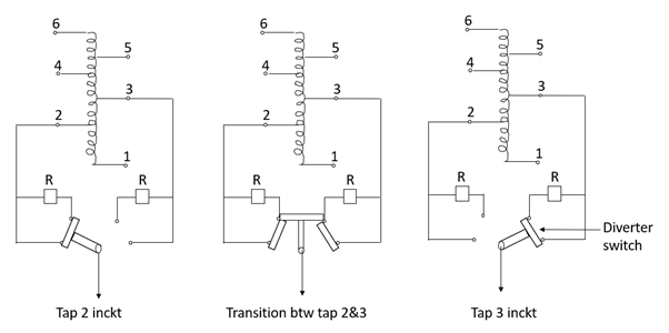
The voltage entry of transmission and distribution system is obtained basically by tap changing.
A winding is provided with several taps. The leads are connected through tap changer to terminal bushings.
By changing the taps, the turns ratio of transformer is changed.
Tap changers are either on load or offload. By changing the turns ratio of transformer, the voltage ratio and the secondary voltage is changed and voltage control is obtained.
The voltage ratio of a transformer can be varied by about ± 16% by means of an on-load tap changer.
OLTC is fitted with power transformer. The winding HV or LV is tapped.
The taps are connected to the diverter to switch off the tap changer.
Tap selector changes the tap. The diverters switch diverts the current.
During diverters operation two tabs may come in contact with each other, to avoid short circuit between two taps resistor is connected across it.
Common OLTC problems:
Open circuit in the diverters:
- The most likely fault in the tap changer is to burn out for disconnection of the resistor which will cause an open circuit inside the diverter resulting arcing in the oil which will cause the oil surge relay to disconnect the transformer.
Excessive wear and tear of diverter moving contacts:
- Modern tap changers are designed for a very large number of operations typically of 5 lacs without excessive wear and tear.
- However older the design, the wear and tear increase. Excessive contacts wear and tear will again cause arcing in oil or if not corrected it will cause the oil surge relay to disconnect the transformer.
The weakening of spring in the diverter or selector switch:
- It will result in poor contact pressure in the switches promoting overheating of contact and increase the contact resistance and degradation of oil.
Degradation of diverter compartment oil:
- If the degradation of diverter compartment oil is not connected in time, the coordinator insulation will break down causing serious damage to the diverter switch and hence disconnection of transformer.
Condition monitoring of OLTC:
Carry out a physical inspection of the selector terminal connection.
Check the proper tightness of leads connected to the selector.
Check the condition of fixed and moving contacts of the selector for arching/carbonization.
Check for proper alignment of the selected assembly.
Check the condition of the oil field in the diverter tank.
Check for any leakage through the diverter tank to the main tanks.
Check for any damage in diverter slow assembly.
Check the continuity of the diverter resistor.
Check the healthiness of copper braid connection.
4.15 Dissolved gas analysis
Transformer oil is known as mineral oil when this oil is proposed the gases are generated.
The composition process takes place due to thermal stress, electrical stresses produced in Transformer.
The electrical stresses of greater magnitude are induced due to the occurrence of the fault.
The decomposition of oil will be different for a different fault that is the gases generated will be different.
These gases get dissolved in transformer oil and oil is contaminated.
If the chemical analysis of the oil sample is done, the fault can be identified.
This process of finding, fault through chemical analysis of dissolved gas is known as dissolved gas analysis.
There is no need to shut down the Transformer. The oil sample can be taken out in live conditions using a suitable arrangement.
Chemical analysis of the oil sample is done in the laboratory analysis process is known as chromatography.
The gases generated during this process are oxygen, nitrogen, hydrogen, methane ethane, ethylene, carbon dioxide, carbon monoxide, acetylene.
For oil, the composition of the above gas in oil should within specified limits as specified in the respective standard.
During the phase of fault, the gases generated get dissolved in oil.
If fault for magnitude is greater and if it sustains greater time, the oil contains a lot of dissolved gases.
The oil is saturated if the generation of gas due to the fault is continuous and gas is released from the oil surface in the form of bubbles.
Normal dissolved gas is a healthy oil.
Types of gas | PPM (parts per million) |
Hydrogen | 100 |
Methane | 50 |
Ethylene | 50 |
Acetylene | 5 |
Carbon dioxide | 5000 |
Carbon monoxide | 200 |
The insulation system in transformer system uses liquid which should be of insulating material.
Solid insulating material inside transformer consists of resins cotton tape, paper.
The liquid insulating material is mineral oil.
The paper used in transformer is impregnated with mineral oil.
Due to thermal stresses, electrical stresses, the life of insulating paper is affected.
The aging effect on the decomposition of paper occurs due to hydrolysis, oxidation, pyrolysis. This is the result of thermal and electrical stresses.
The insulated paper used in transformer is made up of long cellulose fibers.
The cellulose is composed of polymerized glucose molecules. These glucose molecules when subjected to thermal and electrical stress break up into smaller chains.
The degree of polymerization is the count of polymerized glucose rings.
For healthy insulating paper, DP is between 900 to 1400.
For aged insulating paper, DP is between 150 to 200 which is the end of transformer life.
As the insulating paper undergoes the aging process, the glucose rings degrade into smaller units. This lowers the degree of polymerization.
The paper sample is tested to determine DP but it is not possible to take out the paper sample from transformer during live condition i.e., when transformer is energized and even in de-energized condition it is not practically possible to take out some part of the insulating paper for testing.
Because it may cause damage to the insulation system so some other method to determine DP is necessary.
The cellulose molecule of paper reacts with transformer oil and during the polymerization process chemical compound is formed in transformer oil.
This compound is known as furan.
The oil samples can be easily taken out from transformer in live conditions.
This oil is tested and furan analyses are carried out condition from furan analyses, the degree of polymerization is determined.
Table of Furan analysis:
Furan content in PPM | DP | Condition of Transformer |
Upto 0.1 | 700 to 1200 | Healthy |
0.1 to 1 | 450 to 700 | Deterioration in moderation |
1 to 10 | 250 to 450 | Deterioration is excessive |
Greater than 10 | Less than 200 | End of transformer useful life. |
Specification of Transformer oil recommended by IS, RS & IES
Characteristics | Density |
IS 335 at 95°c | 0.89gm/cm cube at 29.5°c maximum |
IES-296(Class I) | 0.895gm/cm cube at 20°c max |
IES-296(Class II) | 0.895gm/cm cube at 20°c max |
BS-148 | 0.895gm/cm cube at 20°c max |
Characteristics | Kon. Viscosity CST |
IS-335 | 27max at 27°c |
IES-296(class-I) | 16.5max at 40°c ,800max at 15°c |
IES-296(Class-II) | 11.0 max at 40°c max |
BS-148 | 16.5 max at 40°c ,800 max at 15°c |
Characteristics | Flashpoint°c |
IS-335(1995) | 140 |
IES-296(Class-I) | 140 |
IES-296(class-II) | 130 |
BS-148 | 140 |
Characteristics | Pour point°c |
IS-335 | -6 |
IES-296(Class-I | -30 |
IES-296(class-II) | -45 |
BS-148 | -30 |
IS specification of Transformer bushing:
The characteristics of a bushing shall be in accordance with IS:2009 & IS:3357
The Bushing insulators except for neutral bushing shall be provided with adjustable arcing arm and hidden shell furnish collaboration gap to decide the actual gap setting.
All-porcelain shall be free from defects and thoroughly verified with smooth hard and uniform brown glass.
It should be capable of satisfactory use under the climate condition.
The minimum specific page distance for condenser type bushing shall be 25mm/Kb or 3mm/kb as per requirement.
The delta value shall not be more than 0.004 at ambient temperature.
The short time current shall be 40kA for 3 sec.
In case of paper, insulation care shall be taken to prevent the ingress of moisture and the final coat of non-hygroscopic varnish should be given to them.
Under voltage leads to
Increase in load current to maintain the KW rating
Mechanical stresses in motors due to lower than normal, torque output is low, it is always safe if the load current is well within the rated current of the motor
Frequency
Increase in supply frequency overload the motor for centrifugal loads Centrifugal machine are governed by the general equation w.r.t pressure, flow, torque, speed & power.
Induction motor fault diagnostic Methods:
Following are the fault diagnostic methods:
1) Temperature measurement and diagnosis:
The temperature of the motor stator winding is measured by an appropriate sensor like RtD (Resistance temp detector) integrated chip like LM35 etc.
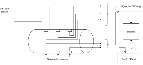
Temperature sensors are embedded in stator winding at different places. The temperature is sensed in different parts of stator windings using a number of temperature sensors.
The Sensor’s output is given to the signal condition block. The overall temperature is computed and displayed.
The temperature of I.M may rise due to voltages unbalance. If unbalance in voltage exceeds 5%, the motor performance deteriorates and temperature rise is more.
Following group shows Variation of temperature due to voltage unbalance
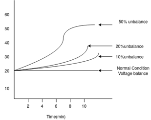
Beyond 10% unbalance, the temperature rise is more which is harmful for the insulation of motor. If the permissible temperature of insulation is exceeded by the life of insulation is reduced by 50% temperature monitoring is critical & important.
2) Vibration measurement & diagnosis:
The vibration occurs due to the following reasons:
a) Electrical Cause:
- The uneven air gap between stator and rotor causing uneven magnetic pau on the rotor
- Loose iron core loose rotor spider
- Shorted stator coil shorted rotor coil
- Open rotor bars defect in rotor wdg
b) Mechanical cause:
- Unbalance cause
- Defective bearing
- Incorrect leveling
- Misalignment
- Reflected vibrations from adjoining m/c, driven loads, etc.
- Bent in the shaft.
- Improper / Loose foundation.
Measurement of vibration:
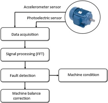
The vibration should be periodically measured and the preventive maintenance can be planned accordingly. The vibrations can be measured by an accelerometer or vibrometer. Accelerometers are fixed on each bearing, the vibrations are measured in two directions norm to the shaft.
The output signal from the accelerometer is proportional to vibrations and it is processed and displayed on the monitor in the form of vibration speed vs time.
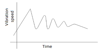
The condition of bearing can be predicted for the vibrations thus vibrations analyses are done.
The coupling to the shaft of machine is removed and machine is run on no load. The vibrations are measured in this no-load running condition.
Permissible values are given below:
Grade of Vibration | Speed of m/c in rpm | Permissible vibration (mm/sec) |
Normal | 600-800/3600 | 1.8 to 4.5 |
Reduced | 600-1800 | 0.71to 1.8 |
Specially reduced | 600-1800 | 1.12 to 2.80 |
Vibrometer: It is a handheld instrument. It consists of a stem and a dial. The stem is touched to the machine shaft in the direction of vibration (i.e., vertical or horizontal) The reading can be directory observes on the dial.
Methods of reducing vibrations:
i) Check mounting bolts, coupling properly. The mounting bolt should be tightened properly. Coupling should be tested using standard procedure.
Ii) The bearings can also become damaged if subjected to external vibrations over a period of time and should be adjusted properly.
Iii) Rubber bushings should be provided at foundation bolt and below foundation beams.
Iv) The shaft alignment between two machines (synchronous generator & turbine) should be checked by a straight edge and feeder gauge. The alignment should be properly adjusted.
3) Signature Analysis:
Motor Current Signature Analysis (MCSA) is a technique used to determine the operating condition of induction motors without interrupting production. Motor current signature analysis is that it is sensing an electrical signal that contains current components. MCSA detect the faults at an early stage and avoid the damage and complete failure of the motor. It uses current sensors like current transformer (CT) & potential transformer (PT) for sensing current and voltage of the motor.
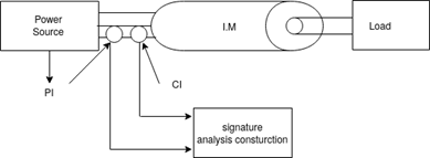
The response of motor in healthy condition and its response during faulty condition is different. The pattern of electrical responses i.e., current & voltage variations are detected and analyzed by the signature analysis instrument. The Fourier analysis of these signals is carried out to diagnose the fault.
The motor current signature analysis can effectively monitor and diagnose the following parameters of I.M
i) Stator winding condition
Ii) Rotor winding condition
Iii) Eccentricity in rotor
Iv) Mechanical coupling (gear, bolt, etc.)
v) Bearing condition
Vi) Load dynamics
The frequency spectrum of current is obtained from measured current. The frequency spectrum of current under healthy condition is treated as following
a) Healthy current frequency spectrum
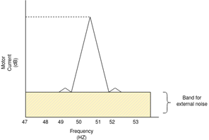
b) Motor current frequency spectrum
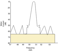
Damaged rotor (as shown in the figure below)
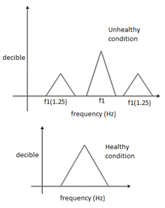
MCSA: (Motor Current Signature Analysis)
1) A FFT (Fast Fourier Transform) analyzer is required for converting the signal from the domain (signal change over time) to frequently domain to see how much signal lies within each give’s frequency over a range of frequency.
2) When a 3  supply is given to the I.M a forward rotating magnetic field is produced which rotates at synchronous speed (Ns).
3) The rotor rotates at Nr and the rotor always rotates at a speed less than Ns.
4) A measure of slipping back of rotor is termed as slip speed which is N2 = (Ns-Nr) = s Ns i.e., actual difference between rotating magnetic field and the actual speed of the rotor.
5) The frequency of rotor current is given as F2 =  = s
= s
6) When broken bars are present or an eccentricity in the gap courses, the magnetic field is no longer constant between rotor and stator creating a slight deviation from the fundamental field.
7) Those deviations induce a current in the rotor and stator with a frequency slightly out of the foundation frequency called sidebands.
8) Broken rotor bars produce a backward rotating magnetic field at negative slip speed w.r.t rotor.
9) That means this rotating magnetic field at that frequency cuts the stationary stator winding & includes current at that frequency i.e., fsb.
10) fsb = f1(1  2s) Hz
11) This gives  2sf sidebands around the supply frequency component f.
12) The speed and torque oscillations occur at 2sf1 & and an upper sideband current component at f1(1 + 2s) is induced in the stator winding.
Live-line working, also known as hot-line maintenance, is the maintenance of electrical equipment, often operating at high voltage, while the equipment is energized. Although this is more hazardous for personnel than working on electrical equipment with the power off, live-line maintenance techniques are used in the electric power distribution industry to avoid the disruption and high economic costs of having to turn off power to customers to perform essential periodic maintenance on transmission lines and other equipment.
Advantages of Hot-Line Maintenance
Greater flexibility of maintenance management
Uninterrupted and timely maintenance
Increase the reliability of the system
Increase the efficiency of the system
Optimize the generation facility
Reduce operating and maintenance costs
Increase safety of operation
Maintain continuity of service to customers
Reduce planned outage maintenance
Escape from regulatory penalty
Early attention to system problems
Methods and Materials used for Hot-Line Maintenance
Hot-stick or distance technique consists of an insulated glass stick to protect the line worker from a grounded source while working on live lines. Generally, this technique is suitable and widely adopted up to 220 kV potential.
Bare-hand technique permits linemen to be in direct contact with potential, being insulated from the grounded object. This live-line methodology is used above 132 kV level and up to 800 kV.
Rubber glove or contact method is a technique in which the person is fully insulated from the ground through an insulated elevated platform and performs live-line work using approved insulating gloves and sleeves. This technique is useful only for distribution networks up to 46 kV.
References:
- P.S. Pabla –Electric Power Distribution, 5th edition, Tata McGraw Hill.
- S. L. Uppal, Electrical Wiring and Costing Estimation, Khanna Publishers, New Delhi.
- Surjit Singh, Electrical wiring, Estimation and Costing, Dhanpat Rai and company, New Delhi.
- Raina K.B. And Bhattacharya S.K., Electrical Design, Estimating and Costing, Tata McGraw Hill, New Delhi
- B.D. Arora-Electrical Wiring, Estimation and Costing- New Heights, New Delhi.
- M.V. Deshpande, Elements of Power Station design and practice, Wheelers Publication.
- S. Sivanagaraju and S. Satyanarayana, Electric Power Transmission and Distribution, Pearson Publication.