Unit - 5
Installation and estimation of distribution system
The proper sizing of an electrical (load bearing) cable is important to ensure that the cable can:
- Operate continuously under full load without being damaged
- Withstand the worst short circuits currents flowing through the cable
- Provide the load with a suitable voltage (and avoid excessive voltage drops)
- Ensure operation of protective devices during an earth fault
All cable sizing methods more or less follow the same basic six step process:
- Gathering data about the cable, its installation conditions, the load that it will carry, etc.
- Determine the minimum cable size based on continuous current carrying capacity
- Determine the minimum cable size based on voltage drop considerations
- Determine the minimum cable size based on short circuit temperature rise
- Determine the minimum cable size based on earth fault loop impedance
- Select the cable based on the lowest of the sizes calculated in step 2, 3, 4 and 5
Step 1: Data Gathering
The first step is to collect the relevant information that is required to perform the sizing calculation. Following data has to be obtained:
Load Details: The characteristics of the load that the cable will supply, which includes: Load type- motor or feeder, three phase/single phase or DC, system /source voltage, full load current, full load power factor.
Cable Construction: The basic characteristics of the cable's physical construction, which includes:
- Conductor material - normally copper or aluminium
- Conductor shape - e.g., circular or shaped
- Conductor type - e.g., stranded or solid
- Conductor surface coating - e.g., plain (no coating), tinned, silver or nickel
- Insulation type - e.g., PVC, XLPE, EPR
Installation Conditions: How the cable will be installed, which includes:
- Above ground or underground
- Installation / arrangement - e.g., for underground cables, is it directly buried or buried in conduit? for above ground cables, is it installed on cable tray / ladder, against a wall, in air, etc.
- Ambient or soil temperature of the installation site
- Cable bunching, i.e., the number of cables that are bunched together
- Cable spacing, i.e., whether cables are installed touching or spaced
- Soil thermal resistivity (for underground cables)
- Depth of laying (for underground cables)
- For single core three -phase cables, are the cables installed in trefoil or laid flat?
Step 2: Cable Selection Based on Current Rating
Current flowing through a cable generates heat through the resistive losses in the conductors, dielectric losses through the insulation and resistive losses from current flowing through any cable screens / shields and armouring. The cable components (particularly the insulation) must be capable of withstanding the temperature rise and heat emanating from the cable. The current carrying capacity of a cable is the maximum current that can flow continuously through a cable. It is sometimes also referred to as the continuous current rating or ampacity of a cable.
Cables with larger conductor cross -sectional areas (i.e., more copper or aluminium) have lower resistive losses and are able to dissipate the heat better than smaller cables. Therefore a 16 mm2 cable will have a higher current carrying capacity than a 4mm2 cable.
Step 3: Voltage Drop
A cable's conductor can be seen as an impedance and as a result, whenever current flows in a cable, there will be a voltage drop across it as per Ohm’s Law (V=IZ). The voltage drop will depend on two things:
Current through the cable – The higher the current, higher the voltage drops
Impedance of the conductor – The larger the impedance, the higher the voltage drop
Step 4: Short Circuit Temperature rise
During a short circuit, a high amount of current can flow through a cable for a short time. This surge in current flow causes a temperature rise within the cable. High temperatures can trigger unwanted reactions in the cable insulation, sheath materials and other components, which can prematurely degrade the condition of the cable. As the cross-sectional area of the cable increases, it can dissipate higher fault currents for a given temperature rise. Therefore, cables should be sized to withstand the largest short circuit that it is expected to see.
Step 5: Earth Fault Loop Impedance
Sometimes it is desirable (or necessary) to consider the earth fault loop impedance of circuit in the sizing of a cable. Suppose a bolted earth fault occurs between an active conductor and earth. During such an earth fault, it is desirable that the upstream protective device acts to interrupt the fault within a maximum disconnection time so as to protect against any inadvertent contact to exposed live parts.
Ideally the circuit will have earth fault protection, in which case the protection will be fast acting and well within the maximum disconnection time. The maximum disconnection time is chosen so that a dangerous touch voltage does not persist for long enough to cause injury or death. For most circuits, a maximum disconnection time of 5s is sufficient, though for portable equipment and socket outlets, a faster disconnection time is desirable (i.e., <1s and will definitely require earth fault protection).
Conductor size calculation
Specification of cables: Before calculating size of conductor for a given load, Specification of cables are always taken into account
Cable having a no. Of stands of a given wire gauge are designated as for example, a cable having 3 strands each of gauge 20. S. W. G, it may be referred to as 3/20s. The other method is giving size of cable in terms of strands and diameter of earth strand in mm.
A cable having 3 strands and each strand of diameter 0. 736 mm may be termed as 3/0. 736 mm.
Size of conductor – Following points must be taken into account while determining size of conductor for internal wining for a given circuit
(a) Minimum size of conductor
(b) Current carrying capacity
(c) Voltage Drop
(a) Minimum size of conductor
Due to mechanical and other considerations minimum size of conductor in use as the following situations is given as under:
1. House wiring – The minimum size of conductor for base wiring sub-circuit shall be 1.5 mm2 or 1. 40mm diameter for aluminum conductor single strand.
2. Underground cable -The minimum size of aluminum conductor for two core cables should be 6mm2. For three core or four core cable it should not be less than 25mm2
3. Size of A. C. R conductor should not be less than 20. 71mm2
(b) Current carrying capacity
Wires are therefore selected keeping into consideration that size of wire (Conductor) is sufficient to carry maximum circuit current. Generally, for wiring work main circuit is divided suitable in different sub- circuits
Total current for each sub-circuit can be calculated as per the load connected to that sub- circuit which is the deciding factor of conductor size as per, ax current in that sub- circuit.
(c) Voltage drop
Before deciding a proper size of a cable to be used in a circuit due consideration must be given to the voltage drop. Fall of pressure or voltage in an eclectic circuit called voltage drop. The voltage drop will take place when current flows through wire and same should be as low as permissible and economical. As per ohms law voltage drop can be determined the resistance is inversely proportional to areas so voltage drop will be less if conductor cross – sectional area is more.
R = 
Metal of the conductor – The metal of the conductor is an important further for determining size of conductor. For instance, the conductor of copper will withstand more current as compared to aluminum due to their different conductivity. The copper conductor is not used due to higher cost of copper but aluminum conductors are in massive use due to economy factor ignoring its Combatively low conductivity.
The permissible voltage drops from supply terminals to any point a wiring system Should not exceed 2% +1 volt for light loads and 5% for declared supply voltage of power loads.
To determine the size of cable, multiply the load current of circuit by length of cable (length of cable for both ways i.e., lead and return for two wires supply and lead only for 3 phase 3 wire balanced load circuit)
Examples a conductor size
1) A single room house receives supply voltage of 200 volts length of wire from switch fuse unit to the working points is 33 meters. The current requirement is only 5 am per. Referring standard table find suitable size 50 that voltage drop is within the limits.
Solution:
The permissible voltage drops =  +1
+1
Referring to table, the minimum size of aluminum conductor of size of aluminum conductor of size 1. 5 mm2 or 1/1. 40 mm diameter having current carrying capacity of 10 amperes if used for installation bet energy meter and main switch let us calculate voltage drop.
Now referring to same table it is given that there will be I volt drop after every 2. 3m for 10 ampere load.
Voltage drop at 10 ampere = 
Voltage drop 1 ampere = 
Voltage drop at 5 ampere = 
= 7. 17 volts
The size is not suitable as it has more voltage drop than permissible values.
Now consulting same table let us take next higher size of 2. 5 mm2/1/1. 80 da wire
This wire has current carrying capacity of 15 ampere and voltage drop of 2. 5 for one volt drop.
Voltage drop at 15 ampere = 
Voltage drop at 1 ampere = 
Voltage drop at 5 ampere = 
This is within the limit of 5 volt drop It is therefore suggested that a cable of size 2. 5 mm2 is selected for installation between pole and energy meter.
2) A residential flat has to be provided wiring system by single phase 230 volts. The length of circuit is 42 meters and electric fittings and appliances require total current of about 40 amperes. Determine size of wire conductor. Refer standard table
Solution:
The permissible voltage
Drop for 230 V supply = 
= 5. 6 Volt
Referring to table, the minimum size of aluminum conductor of size 25 mm2 or 7/2. 24 mm da having current carrying capacity 59 amperes if used for installation between energy meter and main switch let us calculate voltage drop
Now referring to same table it is given that there will be 1 volt drop after every 6. 8 for 59 ampere load
Voltage drop at 59 ampere = 
Voltage drop at 40 ampere at 40 ampere =  = 4. 1874 volts
This drop is within permissible limit It is therefore suggested that a cable of size 25 mm2 is selected for installation.
3) In the section of industry, a main electric (metric) IM is to installed to operate a 400 volts 3 phase 3 wire supply. The distance between the main switch board / control panel to motor terminal box is about 45m select a suitable size of conductor wire standard cable. If motor total current of about 66. 35 ampere.
Solution:
The full load current of motor
Assuming full load p. f of motor = 0. 8
Il =  =
= 
= 6. 35 ampere
Let us selected a 3 C are cable 70 mm2 (19/2. 24) mm da pvc and to check the voltage drop whether it is in permissible limit or not
Permissible voltage drop = 
Now referring table for current rating and voltage drop for pvc, it is given that there will be 1 volt drop after every 14. 7 m for 82 ampere load
Voltage drop at 82 ampere = 
Voltage drop at 1 ampere = 
Voltage drop at 66. 35 ampere = 
= 2. 47 volts
This drop is within the limit and suitable size of 3 core conductor 70 mm2
i.e., area = 70mm2., stands = 19 and da of each conductor = 2. 24 mm
House wiring procedure – Before starting the wiring work a meeting of owner, architect and contractor must be called for discussing deciding the location of meter, points switches etc.
- Consideration must be taken for the future more demand of electric power.
- Electric installation in a new house / building must be immediately taken up after civil constructional work is over.
- For cancelled wiring it should be taken up before plastering as it is to be buried under plaster.
- Power circuit and lighting circuit be taken separate.
- Energy Meters should be installed outside the room so that electric company can inspect as and when required without disturbing house owner.
- Main switch be provided immediately often the energy meter.
- Proper fuse and switches at proper places be installed.
Wiring System
1) Caring capping system – The pvc wires are protected in pvc casing capping. This is popular system of wining
2) Conduit Wiring – The wires are run in metal conduit or pvc conduit. Generally concealed conduit system is used which is under the plaster of walls.
Materials used in wiring System
1) VIR – Vulcanized Rubber wires are used in conductor it wiring system. These are generally single core with one or three stands
2) PVC wire – In poly vinyl chloride wires thermoplastic material is used which resists chemicals venation and direct sunlight. Now a days these wires are extensively used for residential and commercial wiring
3) TRS or CTS Wires – These are tough rubber sheath or cab tyre sheath. These are covered with a tough rubber compound which does not deteriorate even after a long period of use.
General rules for residential and commercial wiring work:
1. The total in the circuit should not exceed 800 walts and no. Of points should not exceed 10in one circuit
2. The lighting and power devices should have the different CIRCUITS
3. The minimum size of conductor in sub – circuit should not be less than 1/8 in case of copper wire and 1/1. 4 mm (1. 5 mm2) in case of aluminum wires.
4. The size of conductor should be such that the voltage drop should not increase more than 3% of the connected voltage when full load current is flowing
5. For lighting load the fuse wire should not exceed 5 ampere capacity for power, it is lo ampere.
6. All the accusatives should be fixed on the round blocks or broach with brass screws
7. In domestic wiring & pin plug should be used
8. All the iron clad appliances, switches etc. should be earthed (e. g. Ceiling fan, break holder etc.
9. All fans should be fixed at height of 2. 5 m from the ground.
10. No inflammable shades should be used in the installation
11. All the switches should be connected through live wire.
12. Neutral should be linked
13 All D. B should be marked as power and light as the case may be
Various Residential Wiring Methods
There are four Methods:
1) Looping is from switch and ceiling rose
2) Looping and from switch
3) Looping and from ceiling use
4) Looping and with Junction Box
1) Looping and from switch and ceiling use
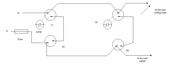
L1 , L2 - Lamps
S1 – S2 – switches
In this type a wire coming and from the main switch connected to first switch from where it goes to a second switch by looping.
From second to third and likewise
Similarly, the neutral wire is carried and by looping from one ceiling rose to the next. The looping in connection is shown in above diagram
Ceiling – A circular mounting on a ceiling, through which the wiring of an electric light passes.
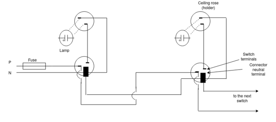
2) Looping and from switch: In this type, special two terminal and connector switches are connected as shown in fig. Both live wire as well as neutral wire are taken to switch and from the switch theses wires go to the next switch by looping
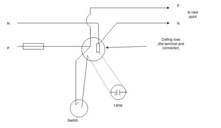
3) Looping and from ceiling rose – Special type of ceiling rose having the terminals and connectors is made use in looping system. Both live and neutral wire entre in the ceiling rose and looped for the second point.
4) Looping and with Junction Box
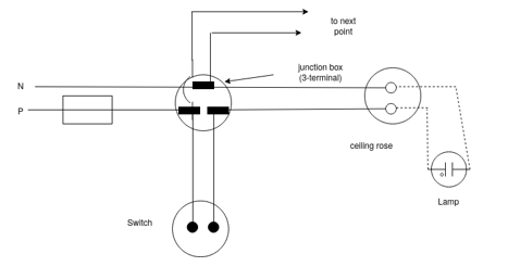
In this type of wiring, phase and neutral conductors from the switches and ceiling rose will terminate in a junction box. The wires are looped from the junction box for the next point. The system is useful for small house
Few Typical wiring Diagrams
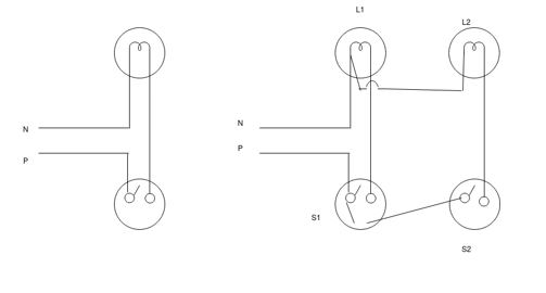
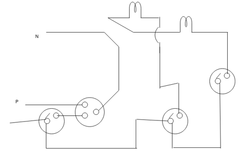
Two light points and one three pin socket
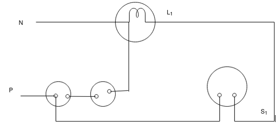
One lamp and one-half point
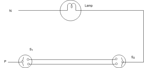
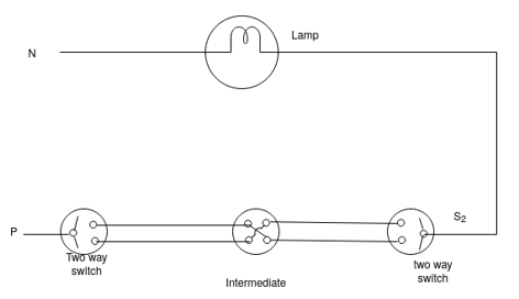

One lamp controlled from 3 phase

The wiring diagram for a small house sharing main I. C. DP switch, energy meter, staircase wiring two, two light points and three pin sockets.
Underground Low Tension service line
- When no. Of buildings are built up side by side or with common walls in no. Of flats in big buildings, it is not convenient to provide service connection by overhead system.
- Hence, a convenient method in this case is to provide the service connection to the main board of one of the buildings with the help of underground cable.
- Then the service connection to the adjacent building is provided by looping from the main board of first building to main board of second building and from main board of second building to main board of third building and so on.
- In doing so, one has to take the precaution in selecting the main underground cable and the looping cables. The current flowing through main underground cable will be equal to same of the load current supplied to all bases.
- Current flowing through looping cable from house no. 1 to house no. 2 will carry excluding required for house no. 1 and so on
- Sometimes, it becomes essential for the house owner to obtain an underground service connection, because the overhead service may spoil the beauty of his house. Also, in a situation of rood crossing or unavoidable circumstance underground service line is the only alternative.
- When the underground service connection is provided, a trench of at least 1 m deep is to be made and run is without sharp bends. The is fixed to the pole with the help of clamps and run through a G. I pipe at least 3 meter above the ground and the pipe may be continued up to the depth of trench.
Installation and estimation of material and of L. T Service line
Steps
- Measure the distance from the pole to the point of termination of service line
- Calculate the total load current required
- Select the type of cable
- Length of cable required
- Cable head, GI. Pipe, bends
- Earthling system
- Pole, Clamps crew saddles, wooden gullies
- Civil work material like sand element etc.
Question: A three phases 4 wire 415/230 V LT line has to be extended for a length of 1 KM, for electrification of a factory. Assuming an average span of 60 meters. Prepare the list of materials required for the same.
Solution:
1. Number of spans
= Length of line / span
= (1 × 1000) / 60
= 16.66 say 17
(Span means distance between two poles)
The number of spans in the one-kilometer line is 17.
2. Total number of supports
= Number of spans + 1
= 17 + 1 = 18 No’s
The total number of supports required for a one-kilometer line is 18.
3. Number of R.C.C poles
= one for tapping + one for dead end + (at 0.5 KM anchoring) = 1 + 1 + 1 = 3
The total number of reinforced cement concrete pole required is 3.
4. Number of P.C.C poles
= Number of supports – R.C.C poles
= 18 – 3 = 15
The number of plain cement concrete pole required is 15.
5. Number of 4-pin cross arms = 18 No’s
How many poles are there that many cross arms are required.
6. Number of 1.1 KV class guy sets
= 1(starting pole) + 1(terminating pole) + 2(at 0.5 KM anchoring pole) = 4 No’s
The number of guy set required is 4 No’s.
7. Number of pin insulators
= (No of intermediate poles + Anchoring) × 4
= (15 + 1) × 4
= 16 × 4 = 64
The number of pin insulator required is 64
8. Number of strain insulators
= 4 * [starting pole + end pole + 2(Anchoring pole)] = 4(2 + 2) = 16
9. Length of conductors
(a). A.C.S.R No.2 weasel conductors for 3-phase conductors with 3% sag = 3 × 1 KM × 1.03 = 3.09 KM
Different types of poles for LT line support
a) Wooden poles d) Steel Towers
b) Steel poles
c) Reinforced Concrete poles
Wooden poles
- It is made up of sal or chir wood
- Its use is limited to low voltage distributions work
- These are used for shorter spans (40 to 50m)
- These are generally used in rural areas
- These poles are cheap and provide good including property.
- The portion of pole, buried underground is treated with preservatives like creosote oil
- This is done to increase life of pole because the portion of pole below the ground level tends to rot and preservatives prevent this happening.
The drawback of wooden poles are:
- These cannot be used for higher voltages (above 20 kV)
- Life is less because of natural decaying process (20-25 years)
- Mechanical strength is less
- Preservative processing is required
- Condition of the pole is to be inspected frequently
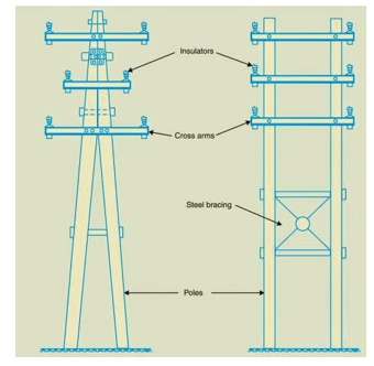
Steel poles
- These are stranger than wooden poles. So, these are suitable for longer spans (50to 80 m)
- The surface of steel poles is galvanized or painted to prevent rusting and corrosion. This enhances life of the pole.
- These are used for distributions purpose in cities. The area of cross-section reduces from bottom to top
- They possess greater mechanical strength Lager life and permit longer spans to be used.
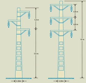
RCC Poles – (Reinforced Concrete poles)
- These poles have become very popular as line supports in recent years
- They have mechanical strength, longer life and permit longer spans than steel poles (80-100m)
- They give good outlook, require little maintenance and have good insulation properties.
- Fig shows diagram for single and double circuit
- The holes in the poles facilitate the climbing of poles and at the same time reduce the weight of line supports
- The main difficulty unit the use of these poles is the high cost of transport owing to their heavyweight. Therefore, such poles are often manufactured at site in order to avoid heavy cost of transportation.
Steel Towers
- In practice wooden, steel and reinforced concrete poles are used for distributions purposes at low voltages up to 11 kV.
- For long distance transmission at higher voltage, steel towers are invariably employed.
- Steel towers have greater mechanical strength, longer life, can withstand most severe climatic conditions and permit the use of longer span (100 to 300m)
- Steel towers have greater mechanical strongly longer life can withstand most severe climatic conditions and permit the use of longer span (100 to 300m)
- The risk of interrupted service due to broken or punctured insulation is considerably reduced owing to longer spans.
- Tower footings are usually grounded by driving rods into earth. This minimizes lightning troubles as each tower acts as lightning conductor.
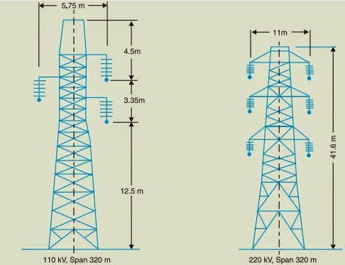
Fig ii) Shows single circuit tower. However, at a moderate additional cost, double circuit tower can be provided as show in fig ii) The double circuit has the advantage it ensures continuity of supply. In case there is breakdown of one circuit, the continuity of supply can be maintained by other circuit.
References:
- P.S. Pabla –Electric Power Distribution, 5th edition, Tata McGraw Hill.
- S. L. Uppal, Electrical Wiring and Costing Estimation, Khanna Publishers, New Delhi.
- Surjit Singh, Electrical wiring, Estimation and Costing, Dhanpat Rai and company, New Delhi.
- Raina K.B. And Bhattacharya S.K., Electrical Design, Estimating and Costing, Tata McGraw Hill, New Delhi
- B.D. Arora-Electrical Wiring, Estimation and Costing, - New Heights, New Delhi.
- M.V. Deshpande, Elements of Power Station design and practice, Wheelers Publication.
- S. Sivanagaraju and S. Satyanarayana, Electric Power Transmission and Distribution, Pearson Publication