Unit - 6
Testing and Electrical Safety
National Fire Protection Association has addressed electrical safety issues in the NFPA 70E standard that has been adopted throughout the United States and copied internationally. Test instruments, such as multimeters, from reputable manufacturers are designed to comply with NFPA 70E category requirements (CAT Ratings). CAT Ratings are based on the location where test instruments will be used.
The other part of the equation is properly selecting and then using the equipment. The following illustration and table of CAT Ratings I-IV summarizes the locations
Overvoltage Category | In Brief | Examples |
CAT IV | Three-phase at utility connection, any outdoor conductors |
|
CAT III | Three-phase distribution, including single-phase commercial lighting |
|
CAT II | Single-phase receptacle connected loads |
|
CAT I | Electronic |
|
When choosing a multimeter, first determine CAT levels you will be operating. Then choose a meter with a voltage rating higher than the maximum voltage you will be testing at each CAT level. For example, an electrician working in CAT III and CAT IV areas can choose a meter rated CAT III 1000 V / CAT IV 600 V. Within a category, a higher voltage rating denotes a higher transient withstand rating, e.g., a CAT III-1000 V meter has superior protection compared to a CAT III-600 V rated meter. The real misunderstanding occurs if someone selects a CAT II-1000 V rated meter thinking that it is superior to a CAT III-600 V meter. Select a meter with the voltage rating suitable for the location (i.e., CAT I, II, III, IV) where you will be operating.
All new completed electrical installation should be tested before connection to the supply, to ensure that the installation is technically sound and free from any possible short circuits, etc. the main reasons, to test a new electrical installation or house wiring before it is switched on to the mains are as follows:
- To know the cause of failure of a particular circuit or circuits or equipment and to locate the exact position of break down.
- To ensure that it is free from faults and is as per electricity rules.
- These tests will receive the attention of the owner before any possible undue damage occurs.
The tests should be made on a new electrical installation before it is switched on to the mains are as under:
- Insulation resistance test between installation and earth.
- Insulation resistance test between conductors.
- Testing of polarity.
- Testing of earth continuity paths.
- Earth resistance test.
Insulation Resistance Test between Installation and Earth
This test is performed to know the standard of insulation of wires and cables used in the installation. It also ensures that the insulation is sufficient enough to avoid any possible leakage of current to earth. The leakage of the current to earth should not exceed 0.02% of the full load current. Before performing insulation resistance test between installation and earth the conditions to be fulfilled for the position of the main switch, fuses, switches, and other points should be as under:
- Main switch in OFF position,
- Fuses beyond the main switch should be in position,
- All switches in ON position.
- All lamps and other equipment should be in their position.
For testing the whole installation, the test is conducted on the main switch. A testing set known as megger is used for the test. It is a special form of the ohmmeter.
To perform this test, the phase and the neutral is short-circuited temporarily at any suitable point as shown in Figure.
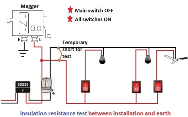
The ‘L’ (line terminal) of the megger is connected to the short circuit point in the main switch and the earth terminal marked (E) is connected to earth continuity conductor or some good earth point near-by. The handle of the tester is turned at a high speed so that sufficient testing voltage is produced. The reading on the dial of the megger is noted. The insulation resistance thus measured should not be less than 0.5 MΩ on a firm, sound and fixed wiring. If the insulation resistance is below this value, the wiring section giving that value should be rewired or checked thoroughly until the required value is obtained.
Insulation Resistance Test between Conductors
To ensure that the insulation of the cables or wires is not damaged and there is no leakage between them, this test is performed. Before performing this test, the position of the main switch, fuses, switches, etc. should be as under:
- Main switch in OFF position,
- All switches in ON position,
- All lamps and other appliances should be removed,
- Fuses beyond the main switch should be in position.
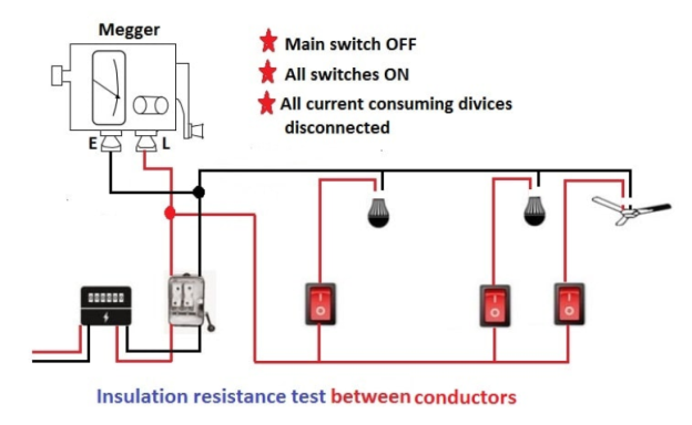
The line terminal of the megger is connected to phase terminal of the installation and the earth terminal of megger is connected to neutral wire. The insulation resistance so measured should not be less than 0.5 MΩ and not more than 1 MΩ.
Use of Guard Terminal
The guard terminal is a third connection that is made to the asset under test. This connection provides a return path for the surface leakage current that, which can otherwise lead to a substantial error in the insulation resistance measurement.
One of the benefits of the guard terminal is that it can be used as a rapid first-line diagnostic tool. Two easy tests can quickly determine whether an asset’s insulation system is truly degrading or if it is simply contaminated with dirt, and therefore in need of proper cleaning. The first test is carried out using the guard terminal and the second test without using it. If the two measured insulation resistance values differ dramatically, then it’s clear that contamination is the underlying issue, causing the instrument, when used without the guard terminal, to show lower insulation resistance values than expected.
The guard terminal is also important when insulation resistance measurements are made periodically on an asset so that the results can be trended. There are many variables that can influence an asset’s measured insulation resistance value, including for example, electrical noise and temperature. So, when trending insulation resistance values over the asset’s lifecycle, the use of the guard terminal for each and every measurement is a necessity. This is because it removes the additional variable of surface leakage which itself changes over time as a result of contamination and differing levels of relative humidity at the time of testing.
Megger provides a guard terminal on a number of its products, starting with the handheld MIT2500, which can test at up to 2.5 kV, right up to the flagship S1-1568 which tests at up to 15 kV.
Method of Measuring Insulation Resistance
There are several instruments for measuring insulation resistance of an electrical equipment.
- Direct-indicating ohmmeter with hand driven dc generator. This is locally known as hand driven megger since Megger is one of the best-known manufacturers of this instrument.
- Direct-indicating ohmmeter with motor driven dc generator. This is locally known as motorized megger.
- Direct-indicating ohmmeter with self-contained battery.
- Direct-indicating ohmmeter with self-contained rectifier. This instrument takes power from an external AC supply.
- Resistance bridge circuit with self-contained galvanometer and battery.
Polarity Test in House Wiring
In a low voltage installation, this test is performed to verify that all single pole switches have been connected to phase wire throughout the installation. It is very necessary to place all switches on phase so that when a switch is made OFF, the connected appliance is quite dead.
If the switch is connected to the neutral wire, then the connected appliance will get phase even if the switch is in OFF position and remain alive.
There is absolutely no difference in the functioning of the switch in either case, but from the safety point of view to avoid shock, etc. the phase should always be given through the switch and neutral direct to the point.
The simple method of conducting the polarity test is by using a test lamp. Before performing this test, the position of the main switch, fuses, switches, etc. should be as under:
- Main switch in ON position,
- All switches in OFF position,
- All lamps and other appliances should be removed.
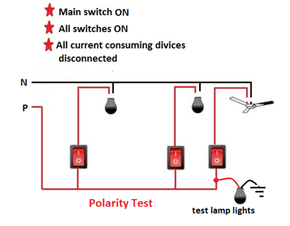
One end of the test lamp is connected to earth wire and the other end to the incoming terminal of the switch. If the lamp lights, it indicates that the switch is connected to phase wire, otherwise to neutral wire.
Earth Continuity Test of Electrical Installation
To perform this test with the help of megger, the main switch is opened, the main fuses are withdrawn, all the switches are made ON and all the lamps are put in position.
The ‘L’ (line terminal) of the megger is connected to the phase conductor in the main switch and ‘E’ (earth terminal) of the megger is connected to an earth point.
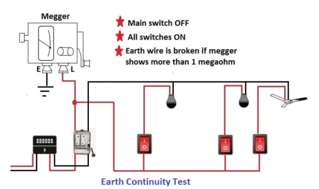
In this test, megger should indicate a resistance value between 0.5 and 1 mega ohm.
In this case, if earthing of all the metallic parts and the earth wire will be in good condition, a sufficient amount of current will flow through test circuit and megger will show a reading up to 1 MΩ.
If it will be in bad condition then it will offer high resistance to the current. As a result, a very low quantity of current will flow and megger will show a reading more than 1MΩ.
Therefore, if the megger shows a high reading (more than 1 MΩ), it means that the main switch or conduit is not properly earthed or the earth wire is broken somewhere requiring correction.
Applications of PAT (Portable Alliance Tester)
There is a legal requirement for any landlord, employer or owner of a place of work or public place, to ensure that all electrical equipment accessible by tenants, employees or the public is maintained in a safe condition, and an acceptable method of ensuring this is by routine electrical testing. This can be performed by electrical contractors, specialist PAT testing organizations, maintenance departments, or facilities management companies. The PAT300 range is suitable for performing portable appliance testing in locations such as hotels, public houses, schools, colleges, nurseries, shops, offices, theatres, banks, restaurants, cafés, sports and leisure facilities, cinemas, factories and hair salons etc. The PAT350 is suitable for use in tool-hire shops where equipment is routinely tested prior to hire, and will perform a flash test in addition to standard PAT tests.
SPECIFICATIONS
Continuity test: The continuity test is a DC test performed automatically in both positive and negative directions. The average of the two results is shown.
Continuity test voltage: 4.0 V d.c. -0% +10% (open circuit)
Continuity test current: 200 mA -0% +10% ±5 mA (into 2 Ω load)
Continuity resistance accuracy: ±5% ±3 digits (0 to 0.49 Ω) ±5% ±5 digits 0.5 to .99 Ω)
Continuity resistance resolution: 10 mΩ (1 to 19.99 Ω)
Display range: 0 to 19.99Ω
Continuity test nulling: up to 9.99Ω
Test duration: User selectable from 1 sec to 20 sec
Insulation test
Insulation test voltage:
250 V d.c-0%/+25% open circuit
500 V d.c-0%/+25% open circuit
(500 V d.c across 0.5 M )
)
Insulation resistance accuracy (230V):
 digits (0 to 19.99 M
 )
)
 digits (20 to 19.99 M
 )
)
Insulation resistance accuracy (110V)
 digits (0 to 10 M
 )
)
Insulation resistance resolution:
0.01 M (0.10 to 99.99 M
 )
)
Display range: 0 to 99.99 M
Test duration: User selectable from 1 sec to 1 minute
Earth Resistance Test
The ability to properly measure ground resistance is essential in preventing costly downtime due to service interruptions caused by poor grounds. The procedures for earth resistance testing are referenced in IEEE Standard No. 81. The most common methods of ground resistance testing used by test technicians are discussed below:
2 point (dead earth) Method:
In areas where driving ground rods may be impractical, the two-point method can be used.
With this method, the resistance of two electrodes in a series is measured by connecting the P1 and C1 terminals to the ground electrode under test; P2 and C2 connect to a separate all-metallic grounding point (like a water pipe or building steel).
The dead earth method is the simplest way to obtain a ground resistance reading but is not as accurate as the three-point method and should only be used as a last resort, it is most effective for quickly testing the connections and conductors between connection points.
Note: The earth electrode under test must be far enough away from the secondary grounding point to be outside its sphere of influence to obtain an accurate reading.
3-point (Fall-of-potential) Method:
The three-point method is the most thorough and reliable test method; used for measuring resistance to earth of an installed grounding electrode.
The standard used as a reference for fall-of-potential testing is IEEE Standard 81: Guide for Measuring Earth Resistivity, Ground Impedance, and Earth Surface Potentials of a Grounding System.
With a four-terminal tester, P1 and C1 terminals on the instrument are jumpered and connected to the earth electrode under test while the C2 reference rod is driven into the earth straight out as far from the electrode under test as possible. Potential reference P2 is then driven into the earth, at a set number of points, roughly on a straight line between C1 and C2. Resistance readings are logged for each P2 point.
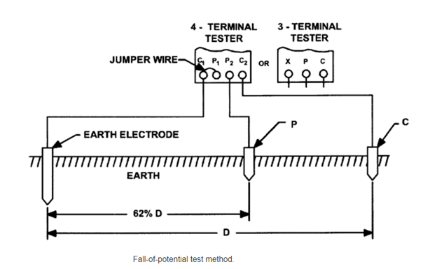
Measurements are plotted on a curve of resistance vs. Distance. Correct earth resistance is read from the curve for the distance that is roughly 62% of the total distance between C1 and C2.
Clamp-on method
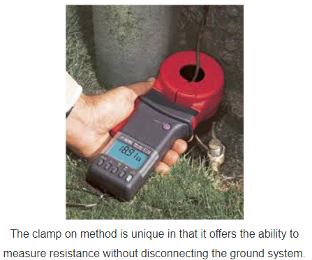
The clamp on method is unique in that it offers the ability to measure resistance without disconnecting the ground system. It is quick, easy, and also includes the bond to ground and overall grounding connection resistances in its measurement.
Measurements are made by "clamping" the tester around the grounding electrode under test, similar to how you would measure current with a multi-meter current clamp.
The tester applies a known voltage without a direct electrical connection via a transmit coil and measures the current via a receive coil. The test is carried out at a high frequency to enable the transformers to be as small and practical as possible.
For the clamp-on method to be effective, there must be a complete grounding circuit in place. The tester measures the complete resistance path (loop) that the signal is taking. All elements of the loop are measured in series. It is important for the operator to understand the limitations of the test method so that he/she does not misuse the instrument and get erroneous or misleading readings.
Some limitations of the clamp-on method include:
- Effective only in situations with multiple grounds in parallel.
- Cannot be used on isolated grounds, not applicable for installation checks or commissioning new sites.
- Cannot be used if an alternate lower resistance return exists not involving the soil, such as with cellular towers or substations.
- Results must be accepted on "faith".
First Aid Kit
Introduction
For most patrons and employees, an injury does not mean a trip to the emergency room. It usually means a trip to the first aid kit with a bump, bruise, cut or crash point. The attending agency employee might apply an ice pack or a Band-Aid, and the apprentice or employee then goes back to work. However, in some situations providing first-aid goes beyond applying an ice pack. It could mean controlling severe bleeding or even bleeding with a potential life or death situation.
Personnel
At least one person, and preferably two or more, trained in first aid and CPR should be available at the agency. The trained first aid responder should be designated, and other workers should know who they are and how to contact them. The trained employee should receive regular in-service training and remain certified.
In all first aid and emergencies, CPR and first aid trained employees should not attempt any medical treatment that exceeds their training level. Contact your local fire department if there are any doubts about a person's health or injuries.
Location
A first aid kit is no longer just tiny box gathering dust in a corner. It is a valued piece of paper and recreation equipment and consideration should be given to its placement, contents, and use, at a minimum, each building of the facility should have a designated location for a well-stocked highly feasible first aid kit. Supplemental kits could be developed for a particular location, person, activity, or use, be it a pool, camp, bus, camping trip, maintenance garage, or special event. The size and contents of the first aid kits depend on the intended use and the type of injuries that are anticipated. The kits may vary in size from a life card that to a large comprehensive first aid box at the special event. Consideration should be given to storing the first aid kit in places that are out of the reach of children, but easily accessible for adults.
Inspection/maintenance:
Providing first aid is the first step in emergency care and everyone and everything needs to be prepared, including the first aid kit. Just like first aid providers need to be prepared through initial training and frequent in-service training, the first aid kids need in service as well. The problem with most first aid kits is that they become functionally incomplete as soon as they are opened unless there is an adequate replacement program, which includes a designated person to inventory and replaces used items. Maintaining quantities of materials in the first aid kit is easier if each kit contains a list showing the original quantity is needed and expiration dates.
For example, first aid kits in facilities may be checked as part of a monthly building inspection. Vehicle first aid kits may be checked by the mechanic during scheduled maintenance. Fanny pack kits may need to be checked and replenished at the end of the day, trip, or related activity.
Contents
Each first aid kit should contain items that may be needed for a particular location or activity. Over the past years, the question of what should be in a first aid kit has gotten complicated. It is recommended that members working with safety equipment vendors should discuss what types of first aid kits and equipment advocate for specific risks and activities. The following is a listing of contents to consider in purchasing first aid kits:
Simple first aid kit contents
First aid manual
An emergency telephone list
Contents list and expiration dates
- A variety of bandages for minor cuts and abrasions.
- Elastic bandage
- Variety of gauze pads
- At least one large trauma dressing
- Rolled gauze
- Medical tape
- Antibiotic ointment
- Alcohol swabs and pads
- Medicines swabs
- Scissors
- Penlight and extra batteries
- Thermometer
- Tweezers
- Eyewash bottle
- Latex gloves
- Emergency blanket
- Ice packs
- Syrup of ipecac
- Disposal bag
Bloodborne pathogens/body fluid protection
- CPR barrier shield
- Latex gloves for other non-permeable barriers
- Face mask
- Food protection
Optional emergency response equipment if required by a lifeguard training agency
- Oxygen cylinder and accessories
- Bag valve mask
- Fluid removal device
- Automated external defibrillator
Forms/reports
- Accident report forms
- Exposure to body fluid report
- Pens
Treatment of Cuts
- Wash Hands - First wash up with soap and water so that bacteria do not gets into the cut and cause an infection.
- Stop the bleeding - Put pressure on the cut with a gauze pad or clean cloth. Keep the pressure on for a few minutes.
- Clean the Wound - Rinse the cut under cool running water or use a saline wound wash. Clean the area around the wound with soap and a wet washcloth. Don’t get soap in the cut, because it can irritate the skin.
- Remove dirt and debris - Use a pair of tweezers cleaned with alcohol to gently pick out any dirt, gravel, glass, or other material in the cut.
Minor first degree and second-degree burns can be treated by following
- Place the burned area under running cool water for at least 5 minutes to reduce swelling.
- Apply an antiseptic spray, antibiotic ointment, or aloe vera cream to soothe the area.
- Loosely wrap a gauze bandage around the burn.
- To relieve pain, take acetaminophen, ibuprofen.
Treatment for Electrical Shock
In the event of electric shock do NOT rush to assist the victim until you are certain that he is no longer in contact with electricity. Otherwise, the current will pass through the victim directly to you.
- If at all possible, turn off the source of electricity (i.e. light switch, circuit breaker, etc.) If this is not an option, use non-conductive material such as plastic or dry wood to separate the source of electricity from the victim.
- Check the victim’s vital signs such as the depth of his breathing and regularity of his heart beat. If either one is affected by exposure to electricity or if the victim is unconscious, begin to perform CPR.
- Treat any areas of the victim’s body that may’ve sustained burns.
- If the victim is responsive and does not appear seriously injured but looks pale or faint, he may be at risk of going into shock. Gently lay him down with his head slightly lower than his chest and his feet elevated.
Artificial Respiration (AR) and CPR
Don't panic. First check the victim. If the victim is unresponsive, call ambulance for help and then return to the victim.
- Place the victim face-off, protecting the head and neck during any movement. Open the airway by pushing back on the forehead and lifting the chin. Place your hair just above the casualties' nose and mouth. Look, listen, and feel for signs of breathing for up to 10 seconds.
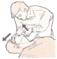
If there is no sign of breathing
2. Take a deep breath and see your mouth around the victim's mouth. Pinch the nostrils closed. Slowly blow air into the victim's mouth for 1 and a half to 2 seconds. Move your mouth away and release the nostrils to allow the air to escape. Look for the chest to listen for air sounds.

If the chest doesn't rise when you blow
3. Reopen the airway by gently tilting the head. Pinched nose again. Make a better seal around the mouth. Try blowing again.
If the chest still doesn't rise
Give first aid for choking
If the chest does rise
4. Check for a pulse. At the neck by sliding two fingers into the groove of the neck just down from the Adams Apple. To detect the pulse can take up to 10 seconds.
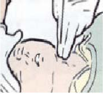
If there is a pulse
5. Continue to breathe into the casualty once every 5 seconds. After 1 minute of check the pulse for 5 to 10 seconds. At the same time look, listen, and feel for breathing.
If there is a pulse and still no breathing
6. Continue AR. Re-check the pulse and breathing every few minutes. Keep giving AR until the casualties start to breathe on their own, and medical help takes over, or you are too tired to continue.
If there is no pulse and you are properly trained, begin CPR
7. Open the airway. Tilt the head back and gently lift the chin. If the victim is not breathing place your mouth over the victim's mouth and pinch the victim's nose close. Give two slow full breath. The person will just rise if you are getting enough air in.
8. Circulation: Look for signs of circulation like normal breathing, cuffing, or movement. If there are no signs of circulation.
9. Start chest compressions: place the heel of one hand on the center of the victim’s chest, right between the nipples. Place the heel of your other hand on top of the first. Press down firmly 15 times.

10. Continue with two breaths and 15 pumps for 4 cycles (about a minute) and check for signs of circulation again (breeding, coughing, and movement). Continue Until Help Arrives.
METHODS OF ARTIFICIAL RESPIRATION
Asphyxia
Asphyxia is a condition in which breathing has stopped. It may be the result of either abnormal, psychological or physical causes.
The psychological causes of asphyxia may include lack of stimulation of the respiratory center in the brain, paralysis of the respiratory center, and the inability of the blood to absorb oxygen from the lungs or to affect the normal exchange of gases in the body tissues.
When it is due to physical causes, it may be spoken of as suffocation. In asphyxia resulting from physical causes, the lungs are deprived of air because of the stoppage of the air passages mechanically. Such causes may include water in the air passages, as in drowning; foreign body in the air passages; a tumor in the air passages; swelling of the mucous membrane in the nose and throat due to inhalation of live steam or an irritating gas; constriction around the neck compressing the windpipe, and the lack of oxygen from any cause. The most frequent causes of stopping of breathing are drowning, electrical shock, and gas poisoning. Asphyxia may be present also in victims of shock or collapse, of extreme exposure to heat or cold and chemical poisoning.
Symptoms of Asphyxia
The symptoms by which the necessity for artificial respiration may be recognized are cyanosis (blueness of the skin and membrane), suspension of respiration, or shallow breathing in some cases of poisoning.
Treatment of Asphyxia
The first thing to do in treatment is to remove the cause of the asphyxia or to remove the patient from the cause. Then administer artificial respiration. Later treat it as for shock. In some cases, artificial respiration can be administered while the patient is being removed from the cause of more suitable surroundings. The treatment for shock can often be started while artificial respiration is being administered.
The patient's mouth should be cleared of any extraction, such as chewing gum, tobacco, false teeth, or mucus, show that there is no interference with the entrance into and escape of air from the lungs.
Artificial respiration should be started immediately. Every moment of delay is serious. It should be continued for at least 4 hours without interruption until normal breathing is established or until the patient is pronounced dead by a medical officer.
The patient must be washed and if natural breeding stops, artificial respiration should be resumed at once. Perform artificial respiration gently and at the proper rate. Roughness may injure the patient.
Every precaution must be taken to prevent further injury to the patient. It may be necessary to give artificial respiration over a long period of time. In the method that required application of pressure, injury to the skin, ribs, and internal organs must be avoided.
Schaefer prone pressure method
The Schaefer prone pressure method can be carried on for a considerable length of time by one person and with out danger to the patient if the operator does not exert undue pressure. Its principle is alternately compressing the chest and releasing the pressure, thus causing air to flow out of and into the lungs. Approximately 60 pounds pressure is probably sufficient even for a large adult. Even though a different method of artificial respiration is to be used later, the Schaefer method should be used until conditions are such as to permit institution of the better method.
- Lay the patient on his abdomen, one arm extended directly overhead, the other arm bend at the elbow, and with the face turned sideways and resting on the hand or fore-arm so that the nose and mouth are free for breathing.
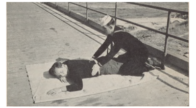
2. Kneel, straddling the patient’s thigh on the side toward which the face is turned, with your knees placed at such a distance from the hip bones as to permit the position shown in the figure. (See fig.) Place the palms of the hands on the small of the back with the fingers resting on the ribs, the little finger just touching the lowest rib, with the thumb and fingers in a natural position and the tips of the fingers just out of sight (See fig.)
3. With arms held straight, swing forward slowly, so that the weight of the body is gradually brought to bear upon the patient. The shoulder should be directly over the heel of the hand at the end of the forward swing. Do not bend the elbows. This operation should take about 2 seconds. (See fig.)
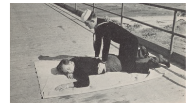
4. Now immediately swing backward to remove the pressure completely. (See fig below)
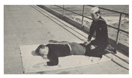
5. After 2 seconds swing forward again. Repeat unhurriedly 12 to 15 times a minute the double movement of compression and release, complete respiration in 4 or 5 seconds.
6. As soon as artificial respiration has been started and while it is being continued, an assistant should lose in any tight clothing about the patient's neck, chest, or waist. The patient should be kept warm.
7. When natural breathing has been restored, the patient should be treated as for shock.
8. In carrying out resuscitation may be necessary to change the operator. The shift can easily be accomplished while counting the rhythm aloud.
EVE method
The Figures below illustrates the shift from Schaefer to Eve and the principal positions of the Eve method. These illustrations also indicate how the inhalator is used for both the Schaefer and Eve methods.
The Eve method makes use of the weight of the abdominal organs alternately to push and pull the diaphragm up and down in the manner of the piston and consists of rocking the patient, securely lashed to the litter or board, over a fulcrum. This method is easy on the patient, is less tiring to the operator, and requires less skill than other methods.
Its disadvantage is that it requires some apparatus, namely a litter, or board, and a fulcrum. The apparatus illustrated is specially designed for the purpose; however, apparatus may be improvised which will accomplish the same effect. In any case, regardless of the type of operators available, the shift from Schaefer to Eve should not be made until it is certain the apparatus is in all respect ready for proper operation.
Procedure:
- The patient is laid face down on a litter or board, with arms outstretched or at the sides, whichever is more convenient. (Figure
- The application of the Schaefer method is resumed as quickly as possible with the least interruption of rhythm. (Figure)
- The ankles and wrists are secured to the litter or board. (Figure)
- If an inhalator is available, it is applied in accordance with the rules and instructions and the directions furnished with the equipment.
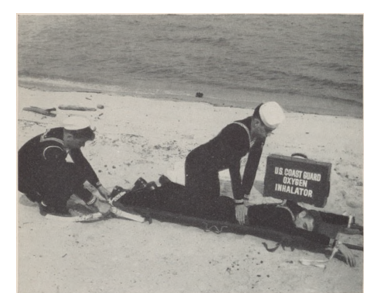
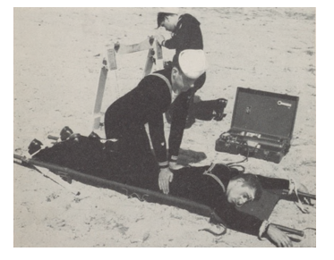
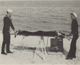
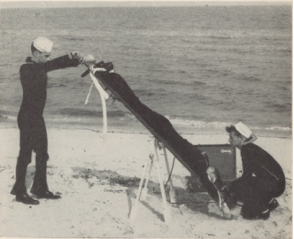
5. The fulcrum is set up near the litter and within reach of the inhalator hose.
6. The litter, or board, is placed on the fulcrum.
7. In resuscitating a drowned person, the first head down tilt should be maintained until no more water drains from the stomach or lungs.
8. The litter, or board, is a rock at 10 complete rocks a minute with a tilt each way of 45 degrees to 50 degrees.
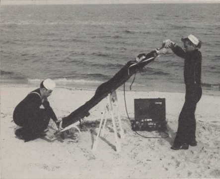
9. Continue until normal breathing is restored or until the patient is pronounced dead by a medical officer.
10. The patient should be kept warm.
11. When artificial respiration has been started, the treatment for shock should be instituted.
The Inhalator
The Inhalator provides a supply of oxygen and carbon dioxide from which the lungs fill when manual artificial respiration is performed.
Since lack of oxygen is the basis for asphyxia from any cause, be it submersion, carbon monoxide, strangulation, electric shock, etc. the use of oxygen in resuscitation is highly desirable. A small percentage of carbon dioxide is added to prevent the loss of this respiratory stimulant during prolonged artificial respiration.
The Inhalator apparatus consists of a tank of oxygen-carbon dioxide mixture, pressure reduction system, flow meter, and rubber hose leading to a nasal tube. The mixture contains 95% Oxygen and 5% carbon dioxide by volume. It is applied as follows:
- Manual artificial respiration is continued without interruption.
- The throat and mouth of the patient are freed of fluid, vomitus, etc. by careful wiping to ensure a free airway. This should be repeated occasionally thereafter.
- With oxygen-carbon dioxide tank open, the flow of 2 liters per minute registered on the flow meter is permitted to pass through the system and out of the nasal tube. The nasal tube is then passed through the nostril to a distance equal to 1 inch less than the distance between the nostril and the ear canal. It is held in position by being passed backward over the head and secured at the forehead by adhesive tape.
- The head of the patient is tilted somewhat back towards the shoulder blades, straightening the air passages and preventing the tongue from falling backward and blocking the windpipe. The flow of oxygen and carbon dioxide mixture is gently raised to 4 liters per minute which is continued thereafter.
- The actual regulation of the inhalator mechanism will depend on the type and make it used. The directions with equipment should be followed. The above are general principles about inhalation from apparatus of any kind.
- Inhalation of oxygen may be rendered entirely safe if precautions are taken against an explosion. There should be no oil whatever on or near fittings and no flighted matches, pipes, cigarettes, etc., allowed in the vicinity of the resuscitation.
General rules and information
- Coast guard procedure for artificial respiration is now officially based on the Schaefer and Eve methods combined with oxygen by inhalation. The Howard Sylvester method is no longer approved as a coast guard method. The general rules outlined below are set forth as a guide to determine the proper course of action under various conditions and to establish effective coordination with appropriate local organizations.
- Inhalation is accomplished through in a letter apparatus which provides a means of supplying oxygen, or a mixture of Oxygen and carbon dioxide, while inspiration and expiration are being induced by manual artificial respiration. Many coast guard units are now equipped within letters and additional units will be furnished the equipment as it becomes available. Whenever a coast guard unit is not provided within a letter, advantage should be taken of oxygen brought to the scene of a resuscitation operation by civilians or other rescue teams.
- The mechanical resuscitator, which is not furnished to coast guard units, is an apparatus which supplies oxygen, or a mixture of Oxygen and carbon dioxide, while inspiration and expiration are being reduced by the application of alternating pressure. Although this equipment has its place when manned by skilled hands, it may operate as a hazard rather than help if it is handled and skillfully. Most resuscitators can be set up to operate as single inhalators. Risks connected with the use of the pressure feature of the resuscitator can this usually be avoided simply by using the resuscitator as an in a letter, in accordance with paragraph 4 (b)
- Comparison of methods and rules for their use:
a) The Schaefer method requires no equipment and is the quickest to put into operation. It should, therefore, be started immediately upon removing a victim of submersion from the water. Oxygen by inhalator should be administered as soon as possible. Although the exchange of air or oxygen is much less with the Schaefer method than with the eve method, it may revive the patient before another method can be applied; otherwise, it serves to expel the water from the stomach and lungs and to keep the patient alive until a more effective method can be applied.
b) The Eve method, which is easier on the patient and affords a greater exchange of oxygen in the lungs, thus greatly enhancing the chances of survival, should be substituted for the Schaefer method as quickly as possible and with the least possible interruption of rhythm. The safest and probably the most effective general-purpose method of resuscitation is the method used in conjunction with the inhalator and accordingly shall take precedence over other methods including the mechanical resuscitator.
c) There is no substitute for thorough training, advanced planning, and good judgment. A specific rule for each case cannot be made. Decisions as to whether a patient should be turned over to another team arriving on the scene, or as to the best choice of the method under a given set of circumstances, must be made by the person in charge. As a general guide to aid coast guard personnel is determining the proper cause of action to follow the various methods are listed below in the order of their relative merit:
- Easy method with oxygen;
- Mechanical resuscitator when manned by the competent team;
- Schaefer method with oxygen;
- Eve method without oxygen;
- Schaefer method without oxygen.
d) In any case when a coast guard team using a manual method gives way to a resuscitator team the person in charge of the resuscitator team becomes responsible for the patient. However, coast guard personnel cells continue to render every assistance they can furnish for bringing the resuscitation to a successful conclusion.
5. Commanding officers and officers in charge shall ascertain whether resuscitation equipment is available in the vicinity of their units and shall endeavor to arrange for joint instruction of personnel of their units and local rescue squares so that efficient and coordinated action may be taken in resuscitation cases.
Shock
Shock is a term used to describe the condition in which the activities of the body are greatly depressed. The usual characteristics are “ashen” face, weekend rapid pulse, great lowering of blood pressure, listlessness, dulling of sensibility, sub normal temperature, and irregular gasping breathing. There may be cold sweat present. Some degree of shock follows most injuries. It may be slide and last only a few seconds, or it may be serious and even fatal. It may come on immediately, or be delayed, coming on several hours later. It may be due to profuse bleeding, exposure to cold, or poisons taken internally. It is almost always found in individuals who have had an interruption of breathing, whatever the cause.
If the patient is not in a condition of shock, he/she should receive treatment to prevent the development of shock. The same measures are used to prevent shock to treat it.
Treatment of shock
When the patient revives, he/she should be kept under close observation for 48 hours even though he/she feels all right. He/she should not be permitted to exert himself/herself in any way.
The fundamental factors in the prevention and treatment of shock are heat, position, and stimulants.
- Heat
- Preserve body heat
- Protect from exposure to cold.
- Remove wet clothing and write the patient.
- Wrap the patient in blankets.
- Application of external heat.
- Care should be used to avoid burning the patient.
- Test the object used for applying heat by holding against the cheek or elbow for half a minute.
- Wrap in a layer of cloth or paper.
b. Methods:
- Hot water bottles.
- Chemical heating pads.
- Glass jars and bottles containing hot water.
- Hot bricks.
- Electrical heating pads.
c. To various regions
- To the feet.
- Between the thighs.
- Along the sides of the body.
- Over the abdomen if not uncomfortable for the patient.
B. Position
- Place the body in such a position that gravity will help the blood flow to the brain and heart.
- Lay the patient on his back with the head low.
- This can be accomplished by raising the foot of the bed, cot, bench, or litter at least 18 inches higher than the head.
- If on a flat surface and other means are not available, elevate the feet, legs, and thighs.
C. Stimulants
Do not attempt to make an unconscious person drink. Give in small quantities at a time.
- Aromatic spirits of ammonia- a teaspoonful in half a glass of water is one of the most satisfactory stimulants. This can be repeated every 30 minutes as needed.
- Coffee and tea both contain the drug caffeine, which is an excellent stimulant. Give the coffee or tea as hot as can be comfortably taken. A cupful may be given every 30 minutes as needed.
- Hot milk, or even hot water, has some stimulating effect, due to the heat.
- An inhalation stimulant, such as an ammonia ampule automatic spirits of ammonia on a handkerchief, maybe place near the patient’s nose in cases in which the patient is not conscious. The one administering the stimulant should always test it on himself first.
- Whiskey should not usually be given.
Electricity Supply Regulations
The Central Electricity Authority made the following regulations further to amend the Central Electricity Authority (Measures relating to Safety and Electric Supply) Regulations, 2010:
(1) These regulations may be called the Central Electricity Authority (Measures relating to Safety and Electric Supply) (Amendment) Regulations, 2019.
(2) They shall come into force on the date of their publication in the Official Gazette.
Safety Provisions for Electric Vehicle Charging Stations
General safety requirement for electric vehicle charging stations. -
(1) All electric vehicle charging stations shall be designed, installed, tested, certified, inspected and connected in accordance with the provisions of this chapter.
(2) All electric vehicle charging stations shall be provided with protection against the overload of input supply and output supply fittings.
(3) All electric vehicle charging points shall be installed so that any socket-outlet of supply is at least 800 millimeter above the finished ground level.
(4)A cord extension set or second supply lead shall not be used in addition to the supply lead for the connection of the electric vehicle to the electric vehicle charging point and it shall be so constructed so that it cannot be used as a cord extension set.
(5) An adaptor shall not be used to connect a vehicle connector to a vehicle inlet.
(6) The electric vehicle parking place shall be such that the connection on the vehicle when parked for charging shall be within five meters from the electric vehicle charging point.
(7) Portable socket-outlets are not permitted to be used for electric vehicle charging.
(8) Suitable lightning protection system shall be provided for the electric vehicles charging stations as per Indian Standards Code IS/ IEC 62305.
(9) The electric vehicle charging station shall be equipped with a protective device against the uncontrolled reverse power flow from vehicle.
(10) One second after having disconnected the electric vehicle from the supply (mains), the voltage between accessible conductive parts or any accessible conductive part and earth shall be less than or equal to 42.4 V peak (30 V rms), or 60 V D.C., and the stored energy available shall be less than 20 J (as per IEC 60950) and if the voltage is greater than 42.4 V peak (30 V rms) or 60 V D.C., or the energy is 20 J or more, a warning label shall be attached in an appropriate position on the charging stations.
(11) A vehicle connector used for Direct Current (D.C.) charging shall be locked on a vehicle inlet if the voltage is higher than 60 V D.C. and the vehicle connector shall not be unlocked (if the locking mechanism is engaged) when hazardous voltage is detected through charging process including after the end of charging and in case of charging system malfunction, a means for safe disconnection shall be provided.
(12) The Direct Current (D.C.) electric vehicle charging point shall disconnect supply of electricity to prevent overvoltage at the battery, if output voltage exceeds maximum voltage limit sent by the vehicle.
(13) The electric vehicle charging points shall not energize the charging cable when the vehicle connector is unlocked and the voltage at which the vehicle connector unlocks shall be lower than 60V.
Earth protection system for charging stations
(1) All residual current device for the protection of supplies for electric vehicle shall, -
- Have a residual operating current of not greater than 30 mA;
- Interrupt all live conductors, including the neutral; and
- Have a performance at least equal to Type A and be in conformity with IS 732-2018.
(2) All residual current devices used for the protection of supplies to electric vehicle shall be permanently marked to identify their function and the location of the charging station or socket outlet they protect.
(3) Each electric vehicle charging points shall be supplied individually by a dedicated final sub-circuit protected by an overcurrent protective device complying with IEC 60947-2, IEC 60947-6-2 or the IEC 60269 series and the overcurrent protective device shall be part of a switchboard.
(4) Co-ordination of various protective devices shall be required.
(5) Where required for service reasons, discrimination (selectivity) shall be maintained between the residual current device protecting a connecting point and a residual current device installed upstream.
(6) All electric vehicle charging stations shall be supplied from a sub-circuit protected by a voltage independent residual current device and also providing personal protection that is compatible with a charging supply for an electric vehicle.
(7) All electric vehicle charging stations shall be provided with an earth continuity monitoring system that disconnects the supply in the event that the earthing connection to the vehicle becomes ineffective.
(8) Earthing of all electric vehicle charging stations shall be as per IS 732.
(9) The cable may be fitted with an earth-connected metal shielding and the cable insulation shall be wear resistant and maintain flexibility over the full temperature range.
(10) A protective earth conductor shall be provided to establish an equipotential connection between the earth terminal of the supply and the conductive parts of the vehicle which shall be of sufficient rating to satisfy the requirements of IEC 60364-5-54.
Requirement to prevent fire for electric vehicle charging stations-
(1) Firefighting system for charging stations shall be provided in accordance with the provisions of these regulations.
(2) Enclosure of charging stations shall be made of fire-retardant material with self-extinguishing property and free from Halogen.
(3) Fire detection, alarm and control system shall be provided as per relevant Indian Standards.
(4) Power supply cables used in charging station or charging points shall conform to IEC 62893-1 and its relevant parts.
Testing of charging stations-
(1) All apparatus of charging stations shall have the insulation resistance value as stipulated in the relevant IEC 61851-1.
(2) The owner of the charging station shall ensure that the tests as specified in the manufacturer’s instructions for the residual current device and the charging station have been carried out.
Inspection and periodic assessment of charging stations-
(1) Every charging station shall be tested and inspected by the owner or the Electrical Inspector or Chartered Electrical Safety Engineer before energization of charging stations.
(2) The owner of the charging station shall ensure that test and inspection of charging station is being carry out every year in the initial period of first three years after the energization of charging station and in every four years thereafter.
(3) The owner of the charging station shall establish and implement a safety assessment programme for regular periodic assessment of the electrical safety of charging station.
Maintenance of records-
(1) The owner of the charging station shall keep records in regard to design, construction and labelling to be compatible with a supply of standard voltage at a nominal frequency of 50 Hertz of the charging station.
(2) The owner of the charging station shall keep records of the relevant test certificate as indicated in these regulations and as per IEC 61851.
(3) The owner of the charging station shall keep records of the results of every inspection, testing and periodic assessment and details of any issues observed during the assessment and any actions required to be taken in relation to those issues.
(4) The owner of the charging station shall retain a copy of all records, as specified in sub regulation (1), (2) and (3) of above, either in hard form or in electronic form, for at least seven years and shall provide a copy of the records to the officials during the inspection.
International Standard for charging stations-
(1) The safety provisions of all Alternating Current charging stations shall be in accordance with IEC 61851-1, IEC 61851-21 and IEC 61851-22.
(2) The safety provisions of all Direct Current charging stations shall be in accordance with IEC 61851-1, IEC 61851-21, IEC 61851-23 and IEC 61851-24.
(3) Where the connection point is installed outdoors, or in a damp location, the equipment shall have a degree of protection of at least IPX4 (Ingress Protection Code) in accordance with IEC 60529.”.
Factory Act
The Factories Act, 1948 (Act No. 63 of 1948), as amended by the Factories (Amendment) Act, 1987 (Act 20 of 1987), served to assist in formulating national policies in India with respect to occupational safety and health in factories and docks in India. It dealt with various problems concerning safety, health, efficiency and well-being of the persons at work places. It was replaced by the Occupational Safety, Health and Working Conditions Code, 2020.
The Act is administered by the Ministry of Labour and Employment in India through its Directorate General Factory Advice Service & Labour Institutes (DGFASLI) and by the State Governments through their factory inspectorates. DGFASLI advises the Central and State Governments on administration of the Factories Act and coordinating the factory inspection services in the States.
The Act is applicable to any factory using power & employing 10 or more workers and if not using power, employing 20 or more workers on any day of the preceding twelve months, and in any part of which a manufacturing process is being carried on with the aid of power, or is ordinarily so carried on, or whereon twenty or more workers are working, or were working on any day of the preceding twelve months, and in any part of which a manufacturing process is being carried on without the aid of power, or is ordinarily so carried on; but this does not include a mine, or a mobile unit belonging to the armed forces of the union, a railway running shed or a hotel, restaurant or eating place.
Indian electricity rules of Central Electricity Authority (CEA)
CEAR namely Central Electricity Authority (Measures relating to Safety and Electric Supply) Regulations, 2010 are regulations framed by Central Electricity Authority of India under Indian Electricity Act, 2003, to regulate measures relating to safety and electric supply in India.
Under CEAR, rule 41, there is specific provision of earthing neutral wire of a 3-phase, 4-wire system and the additional third wire of a 2- phase, 3-wire system. Earthing is to be done with two separate connections. Grounding system also to have minimum two or more earth pits (electrode) such that proper grounding takes place. As per the rule 42, installation with load above 5 kW exceeding 250 V shall have suitable Earth leakage protective device to isolate the load in case of earth fault or leakage.
Neutral and earth run separately on overhead line/cables. Separate conductor for overhead lines and armouring of cables are used for earth connection. Additional earth electrodes/pits are installed at user ends for proper earth.
All metal casing or metallic coverings of electric supply line or apparatus to be connected with earth and all such earthling points shall be so joined to make good mechanical and electrical connection in complete system.
Earthing in an underground mine shall be carried out by connection to an earthing system at the surface of the mine as per rule 99.
As per rule 100, protective equipment is to be placed in the mines for automatic disconnection of supply when there is earth fault exceeding 750 milliampere in 250 V to 1000 Volt installations. For open cast mine the limit is 50 ampere in installations of voltage exceeding 1100 V and up to 11 kV. The earth leakage current is to be restricted by placing suitable neutral grounding resistance (NGR) in all the distribution transformers.
Salient Features
Chapter - I Definitions
1 Short title and Commencement
2 Definitions
Chapter - II
3 Designating person(s) to operate and carry out the work on electrical lines and apparatus
4 Inspection of designated officers and other safety measures
5 Electrical Safety Officer
6 Safety measures for operation and maintenance of electric plants
7 Safety measures for operation and maintenance of transmission, distribution systems
8 Keeping of records and inspection there of
9 Deposit of maps
10 Deposit of printed copies
11 Plan for area of supply to be made and kept open for inspection
Chapter - III General safety requirements
12 General safety requirements, pertaining to construction, installation, protection, operation and maintenance of electric supply lines apparatus
13 Service lines and apparatus on consumer’s premises
14 Switchgear on consumer’s premises
15 Identification of earthed and earthed neutral conductors and position of switches and switchgear therein
16 Earthed terminal on consumer’s premises
17 Accessibility of bare conductors
18 Danger Notices
19 Handling of electric supply lines and apparatus
20 Supply to vehicles and cranes
21 Cables for portable or transportable apparatus
22 Cables protected by bituminous materials
23 Street boxes
24 Distinction of different circuits
25 Distinction of the installations having more than one feed
26 Accidental charging
27 Provisions applicable to protective equipment
28 Display of instructions for resuscitation of persons suffering from electric shock
29 Precautions to be adopted by consumers, owners, occupiers, electrical contractors, electrical workmen and suppliers
30 Periodical inspection and-testing of Installations
31 Testing of consumer's installation
32 Installation and testing of generating units
Chapter - IV General conditions relating to supply and use of electricity
33 Precautions against leakage before connection
34 Leakage on consumer's premises
35 Supply and use of electricity
36 Provisions for supply and use of electricity in multi-storied building more than 15 meters in height
37 Conditions applicable to installations of voltage exceeding 250 Volts
38 Appeal to Electrical Inspector in regard to defects
39 Precautions against failure of supply and notice of failures
Chapter - V Safety Provisions for Electrical Installations and apparatus of voltage not exceeding 650 volts
40 Test for resistance of insulation
41 Connection with earth
42 Earth leakage protective device
Chapter - VI Safety Provisions for Electrical Installations and apparatus of voltage exceeding 650 volts
43 Approval by Electrical Inspector
44 Use of electricity at voltage exceeding 650 Volts
45 Inter-locks and protection for use of electricity at voltage exceeding 650 Volts
46 Testing, Operation and Maintenance
47 Precautions to be taken against excess leakage in case of metal sheathed electric supply lines
48 Connection with earth for apparatus exceeding 650 V
49 General conditions as to transformation and control of electricity
50 Pole type sub-stations
51 Condensers
52 Supply to luminous tube sign installations of voltage exceeding 650 Volts but not exceeding 33 kV
53 Supply to electrode boilers of voltage exceeding 650 Volt but not exceeding 33 kV
54 Supply to X-ray and high frequency installations
Chapter - VII Safety requirements for overhead lines, underground cables and generating stations
55 Material and strength
56 Joints
57 Maximum stresses and factors of safety
58 Clearance above ground of the lowest conductor of overhead lines
59 Clearance between conductors and trolley wires
60 Clearance from buildings of lines of voltage and service lines not exceeding 650 Volts
61 Clearances from buildings of lines of voltage exceeding 650 V
62 Conductors at different voltages on same supports
63 Erection or alteration of buildings, structures, flood banks and elevation of roads
64 Transporting and storing of material near overhead lines
65 General clearances
66 Routes proximity to aerodromes
67 Maximum interval between supports
68 Conditions to apply where telecommunication lines and power lines are carried on same supports
69 Lines crossing or approaching each other and lines crossing street and road
70 Guarding
71 Service lines from overhead lines
72 Earthing
73 Safety and protective devices
74 Protection against lightning
75 Unused overhead lines
76 Laying of cables
77 Protection against electromagnetic interference
Chapter - VIII Safety requirements for Electric Traction
78 Application of chapter
79 Voltage of supply to vehicle
80 Insulation of lines
81 Insulation of returns
82 Proximity to metallic pipes
83 Difference of potential on return
84 Leakage on conduit system
85 Leakage on system other than conduit system
86 Passengers not to have access to electric circuit
87 Isolation of sections
88 Minimum size and strength of trolley wire
89 Height of trolley wire and length of span
90 Earthing of guard wires
91 Proximity to magnetic observatories and laboratories
92 Records
Chapter - IX Safety requirements for mines and oil fields
93 Application of chapter
94 Responsibility for observance
95 Notices
The worker should treat ‘Electricity’ as the ‘Hazard’ and select protection accordingly Hazards due to electricity can classified into three categories.
1) Hazard due to Electric shock:
These are the areas where electric shocks are likely to be received, if person comes in contact or knowingly or unknowingly touches the live parts, leakage parts. Insulation damaging, fault in earthing system are the main causes.
2) Hazard due to an Electric Arc:
In some areas, electric arc is produced frequently, arcing if ignored and not taken care of then the electric arc between two points when voltage between the points exceeds and dielectric strength between the points is broken, severe temperature is developed and arcing is produced which creates major hazards.
3) Hazard due to an Electric Blast:
An electrical blast, or explosion, as it is often termed, is the result of the heating effects of electrical current and the ensuing arc. This phenomenon occurs in nature as the thunder that accompanies lightning, a natural form of an electrical arc.
Electrical Safety Organizations- OSHA
The primary goal of the Occupational Safety and Health Administration (OSHA) is “to ensure safe and healthful conditions for every American worker.” OSHA currently has thousands of rules and regulations that cover workplace safety. Federal and state OSHA programs enforce regulations through workplace inspections, voluntary assistance programs, and training activities. Citations and fines are also levied for violations found during inspections.
The General Duty Clause Section 5(a)(1) of the Occupational Safety and Health Act of 1970 reads, 5. Duties
(a) Each Employer
(1) Shall furnish to each of his employees employment and a place of employment which are free from recognized hazards that are causing or are likely to cause death or serious physical harm to his employees;”
The “General Duty Clause” is essentially the mission that OSHA strives to enforce. It is also often cited when OSHA investigates a workplace accident. Many OSHA regulations are prescriptive in nature like the “General Duty Clause”. In other words, OSHA is the “shall” or the reason for addressing an issue. In some cases, OSHA will also provide detailed information on how to meet the requirements. In other instances, OSHA refers to national safety organizations such as NFPA to provide the required level of detail to meet the regulations. In either case, OSHA covers all employees and all employers.
OSHA Regulations
Published by the U.S. Federal Register, OSHA regulations can be found in the Code of Federal Regulations (CFR) under Title 2. More specifically, and legally enforced by OSHA, Subpart S (Parts 110.301 to 110.3) addresses “Electrical” safety standards and covers the practical safeguarding of electrical workers. Subpart S is divided into four major divisions:
- Design safety standards
- Safety-related work practices
- Safety-related maintenance requirements
- Safety requirements for special equipment
References:
[R1] P.S. Pabla –Electric Power Distribution, 5th edition, Tata McGraw Hill.
[R2] S. L. Uppal, Electrical Wiring and Costing Estimation, Khanna Publishers, New Delhi.
[R3] Surjit Singh, Electrical wiring, Estimation and Costing, Dhanpat Rai, and company, New Delhi.
[R4] Raina K.B. And Bhattacharya S.K., Electrical Design, Estimating and Costing, Tata McGraw Hill, New Delhi
[R5] B.D. Arora-Electrical Wiring, Estimation and Costing,- New Heights, New Delhi.
[R6] M.V. Deshpande, Elements of Power Station design and practice, Wheelers Publication.
[R7] S. Sivanagaraju and S. Satyanarayana, Electric Power Transmission and Distribution, Pearson Publication.
[R8] Megger PAT300 SERIES- Manual
[R9] ELECTRICAL SAFETY HAZARDS HANDBOOK - Littelfuse
[R10] United States Coast Guard, Treasury Department: Methods of Artificial Respiration