Unit - 1
Transformer Design: Part 1
Thermal energy is related to the temperature of Maher for a given material and mass. The higher the temperature, the greater is its thermal energy. When two bodies are at different temperature, thermal energy transfers from one with higher temperature to the one with lower temperature. Heat always transfers from hot to cold.
The process of heat transfer in case of Xmer and electromechanical energy conversion in the case of rotating electrical machines involves currents in the conductor and fluxes in ferromagnetic parts. There are I²R losses in winding and core losses in core of Xmer. Moreover, losses occur in Tank walls, end plates and covers on account of flux leakage. The losses appear as heat and therefore the temperature of every affected parts rises above the ambient medium which is normally the surrounding air.
The heated parts of an electrical m/c dissipate heat into their surrounding by conduction, convection assisted by radiation.
Heat is typically given the symbol Q and is expressed in Joules in SI units. The rate of heat transfer is measured in WaH(W) equal to joules per second and is denoted by q. The rate of heat transfer per unit area is measured in waHs per area (W/m²) and uses q for the symbol.
The heated part of any electrical machines dissipate heat into their surrounding by conduction, convection, assisted by radiation.
Conduction- conduction is transferred through solid or stationary fluids. When we touch a hot object, the heat we feel is transferred through the skin by conduction. In fluid, conduction occurs through collision between freely moving molecules.
Convection- Convection uses the motion of fluids to transfer heat.
Radiation –Radioactive heat transfer does not require a medium to pass through, thus it is only form of heat transfer present in vacuum.
Conduction
The mode of dissipation of heat is important in case of solid parts of machines like copper, iron and insulation.
Consider two points in electric circuit having potential V1 and V2, the current flowing between them is

R electrical resistance of conducting medium between them.
Similarly, we can also write the equation for heat flow for conduction between two surfaces separated by heat conducting medium as

QconHeat dissipated by conduction , w
 temperature of two bounding surface, °C
Rc thermal resistance of conduction medium, thermal ohm/°C/W.
Thermal Resistance –It is defined as the thermal resistance which causes a drop of 1°C per watt of heat flow. The thermal resistance like electrical resistance can be written as

Where
 = thermal resistivity of the material.
 Thermal conductivity
t = length of medium
s = area of surface separated by medium surface area (outside part of uppermost layer of something)
So, eqn. 1 can be written as
 W
W
So, heat dissipated per unit surface area by conduction is

Temp difference across conducting medium

 ----------------------(2)
From above eqn. 2, we can say that material having high value of thermal resistivity will dissipate less amount of heat.
Material Thermal Resistivity
Air 20
Cotton cloth 14
Micanite 8
Compressed paper 8
Paper 7.5
Xmer coil 6.25
Press board 6
Varnished cloth 5
Mica tape 2.6 to 6.6
Asbestos 4
Mica 3
Sheet steel-
Along lamination 0.02
Across lamination 0.05 to 0.1
Brass 0.01
Al 0.005
Cu 0.0026
Hence, air has greater thermal resistivity than paper, since presence of air pocket in insulation in mic could have disastrous effect.
Q. A Cu bar 12mm in diameter is insulated with micanite tube which fits tightly around the bar and into the rotor slot of an induction motor. The micanite tube is 1.5mm thick and its resistivity is 8 ohm m. Calculate the loss that will pass from Cu bar to iron if temperature difference of 250C is maintained b/q them. The length of bar is 0.2 m.
Given – Diameter of Cu = 12mm = 12 × 10-3 m
Thickness of tube = 1.5 mm = 1.5 × 10⁻³ m
 8 ohm m ,
  = 250C
Length of bar = 0.2 m
To find: Qcon = ? = 

S =Perimeter = 

So, Ro =  ohm = 1.415 ohms
Qcon = 25/1.415 = 17.67 W
# Surface area is the extent of surface but the perimeter is continuous line that forms boundary.
Q. The thermal resistivity of assembled armature laminations is 20 times as great along the direction of lamination as in the direction across the laminations. Calculate the loss that will be conducted across lamination in a stack 40mm thick and 6000 mm2 in cross section with difference of 20oC. Given that difference of 5oC will cause 25 W to be conducted through cross-section of 2500 mm2 in area and 20mm thick measured along the laminations.
Soln. It is given that :  = 20
= 20
Now, we have to find the loss that will be conducted across lamination. To find loss across lamination, we have to find value  along laminations.
Given data along the laminations-
Qcon = 25W  = 50C
= 50C
T = 20 mm = 20
S = 2500 mm2 = 2500  = 25
= 25 
So, Qcon = 
25 = 
So,  along direction of lamination = 0.025 ohm m.
Now, resistivity across lamination = 20  0.025 = 0.5 ohm m
Data across laminations
T = 40mm = 40 
S = 6000 mm2 = 6000  m2
m2
 = 0.5 ohm m
 = 20 0C

Qcon across lamination = 6W
Radiation
Electromagnetic waves are required to transfer heat.
Heat dissipated by radiation from surface depends upon its temp. And its other characteristics like colour, roughness, etc.
Ex. Sun’s heat reaching us.
The heat radiated per unit surface is given by Stefan Boltzmann Law

T1 = Absolute temp. Of emitting surface in K
To = Absolute temp. Of ambient medium.
 = Temp. Of emitting surface and ambient medium respectively.
E = Coefficient of emissivity
( 1 for perfect black body and always less than 1 for others )
Emissivity and Absorption factor
Surface Emissivity ‘e’ Absorption factor
Aluminium 0.1 0.15
Cu 0.15 -
Steel-
Rough 0.24 -
Sheet 0.55 -
Metal paint Al 0.55 0.55
Lead paints-
White 0.90 0.25
Grey 0.95 0.75
The specific heat dissipation value by radiation for surface painted with dull metallic paints is large.
Hence, all electrical m/c are painted with dull metallic paints in order to have large heat dissipation. This keeps temp. Rise of m/c to low value.
Now, eqn. 1 can be written as-
qrad = = 5.7×10⁻⁸ e (T1 – To )( T13 + T12To + T1T02 +T03 ) --------------(2)
a4 – b4 = (a-b)(a+b)(a2+b2) = (a-b)(a3+b3+ab2+a2b)
Now, T1 – T0 = [(273+ ) – (273+
 ] =
] =  =
=
It represents temp. Rise of body above ambient medium.
T13 + T12To + T1T02 +T03 varies little within conventional temp. Limits for electrical m/c. So, eqn. can be written as
qrad = 5.7×10⁻⁸ e Kr (T1 – T0)
qrad = 5.7×10⁻⁸ e Kr ( )
)
Where Kr = T13 + T12To + T1T02 +T03 qrad = 
e emissivity value for cast iron or steel surface varnished insulation etc is b/w 0.90 to 0.97. Assuming a value of 0.83 for safety we have
qrad = 5.7×10-8 ×0.83 × Kr ( )
)
= 4.8 × 10⁻⁸ Kr ( )
)
qrad =  (
( )
)
Where,  = 4.8 × 10⁻⁸ Kr= Modified specified heat dissipation or emissivity measured in W/m2 at temp rise of 1 oC. It is not cons. As its value depend on
So, total heat dissipated by radiation is
Qrad = qrad × S
Qrad =  S Watt
In electrical rotating m/c and and Xmer radiation does not normally occur by itself and in almost every case it is a accompanied by convection. So,
qrad = 2.9e W/m2 is used.
Q. A heat radiating body can be assumed to be spherical surface with coefficient of emissivity = 0.8.
The temp. Of body is 60oC and that of walls of room in which it is placed is 200C. Find heat radiated from body in watt per square metres.
Soln. e = 0.8 T1 = 273+60 = 333 K
T2 = 273+20 = 293 K
qrad == 5.7×10⁻⁸ e (T14 – To4) W/m2
= = 5.7×10⁻⁸ 0.8(3334 – 2934) = 224.6 W/m2.
Q. A 250 V, 1 kW single element resistor is made from 0.2mm thick nickel chrome strip. The temp. Of strip is not to exceed 300oC over the ambient temp of 30oC. Calculate length and width of strip. Assume emissivity of nickel chrome 10-6 ohm m.
Soln. V = 250V P = 1000 W
Thickness, t = 0.2mm = 0.2×10⁻³ m
T1 = 300+30 = 330 oC = 330+273 K = 603 K
To = 30+273 = 303 K
e = 0.9×0.75 =0.675 [ ]
]
 = 10-6 ohm m.
To find - Length (l) width (w)
Now, we know that
qrad = = 5.7×10⁻⁸ e (T14 – To4)= 5.7×10⁻⁸ (0.675)(6034 – 3034) = 4762.53 W/m2.
Power =VI = V.(V/R)= V2/R
Let l =length of strip
t = thickness of strip
w = width of strip
A = cross section of strip


 ----------(1)
We know that
qrad =4762.53 W/m2 and also heat dissipated by radiation
Qrad = qrad (S) = 4762.53 (2)(wl)
So, 1000 = 4762.53 (2wl)
Lw = 0.1049 ---------------(2)
On solving 1 and 2,
l = 36.22m w = 2.89 m
Convection
Fluid (liquid / gases) coming in contact with hot body becomes lighter and rise giving place to cooler particles, thereby creating thermal heat and consequent circulation known as natural convection.
Heat transfer takes place by actual motion of molecules of substance and mostly takes place in liquid and gases. They are classified into two categories.
Natural Convection and artificial convection.
Natural Convection - Liquid and gas particles near heated body becomes lighter and rises giving place to cooler particles which in turn gets heated and rise. This natural process is due to change in fluid density known as Natural Convection.
The heat dissipated per unit surface by natural Convection of hot body is given by

Kc = constant depending on shape and dimension of hot body
n =constant depending upon shape and dimension of hot body. Its value lies between 1 and 1.25.
 1 = temperature of emitting surface
 o= temperature of ambient medium.
Taking n=1,

 = specific heat dissipation or emissivities due to Convection measured in (W/m²) °C
Total heat dissipated by convection

Convection is complicated phenomena and heat convected depends upon many variables such as
i) power density
Ii) temperature difference between heated surface and coolant
Iii) height, orientation configuration and condition of heated surface
Iv) thermal resistivity density specific heat viscosity and coefficient of volume expansion of fluid.
v) Gravitational constant.
To find heat convected, the following formula have been developed for range and structure of m/c.

For vertical tube of diameter d

d diameter of tube (meter)
Artificial Convection
In modern m/c, heat is removed by artificial circulation of cooling medium, for example Xmer tank may be cooled by blasting air on it for a turbo alternator is cooled by circulating hydrogen. This is known as artificial convection.
The problem of calculating heat dissipation by artificial conduction is very complex as it mainly depends on constructional features of m/c. These features are different for every m/c. So, there is no exact relationship. However, one of the most widely used formula for Air blast on open surface is

 = specific heat dissipated by blast surface
 = specific heat dissipated by natural convection
V = relative velocity of cooled surface and air blast
Kv = constant, depending upon blast is uniform or non uniform
= 103 for uniform blast.
Values of Kv comes down to 0.5 for non uniform blast.
The temperature of m/c rises when it is run under steady load conditions starting from cold conditions. The temperature at first increases at the rate determined by power wasted. As the temperature increases, active parts of m/c dissipate heat partly by conduction, partly by radiation and in most cases largely by mean of air cooling.
The temperature of any part of a m/c not only depends on heat produced in itself but also on heat produced in other parts. This is because there is always heat flow from one part of to other. For example, the heat produced in the part of winding embedded in the slot flows through the insulation to the lamination partially to end windings. Thus, the end windings have to transfer to the air not only the heat produced in them but also a part of heat produced in slot portion of winding.
Electrical m/c are not homogenous bodies. Their parts are made up of different material like Cu, iron and insulation. All these materials have different thermal resistivities and due to this, it is rather difficult to calculate temperature of part of the m/c. So, it is worthwhile taking theory of heating of homogenous bodies as basis for analysing the process of m/c heating.
Let
Q = power loss or heat developed
G = wt. Of active parts of m/c
h = specific heat
S = area of cooling surface
 = specific heat dissipation
c = 1/ = cooling coefficient
 = temp. Rise at any time t
d = temp rise in small interval dt
 m= final steady temp rise while heating
 n = final steady temp rise while cooling
 i = initial temp rise over ambient medium
Tn = heating time constant
Tc = cooling time constant
t = Time
Heat energy developed in the body during an infinitely small time dt = heat energy developed per second × dt = Qdt ---------- (1)
The heat energy stored in the body = wt of body × specific heat × difference in temp.
= Ghd ----------------(2)
Heat energy dissipated by body into ambient medium due to radiation, conduction and convection
= specific heat dissipation × surface × temp.rise × time

Total heat developed in m/c = heat stored + heat dissipated


Dividing by Gh (RHS)

Now solving above eqn.
 --------------------------(5)
K= constant of integration, to find value of K apply boundary conditions.

 ------------------------------(6)
Put value of K in eq 5


 --------------------(7)
The m/c reaches a final steady temp rise when t = ∞
Ie under this, there is no further temp rise and rate of heat production and dissipation are equal.
Ie d =0 or Ghd
 =0
=0
So from eqn 4.


Putting in eqn. 7


If m/c starts from cold condition
 --------------------(8)
Above eqn is eqn of temp rise with time.
The temp. Rise time curve will be exponential.
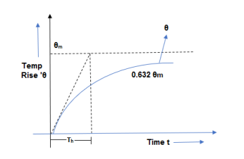
Initially, heat rises very fast but after some time, it becomes constant ie exponential increase of heat.
Heat time constant
From eqn 8

Putting t=Th in above expression


So, heating time is the time taken by m/c to attain 0.632 of its final steady temperature rise.
The heating time constant of m/c is the index of time taken by m/c to attain its final steady temperature rise.
Considering we can say that time constant is inversely proportional to specific heat dissipation.
 large so Th small well-ventilated m/c
 Small so Th large poor ventilated m/c.
Cooling Time constant
As we know that

After this, whole steps are same as we did in heat time constant till eqn. 7

Here, 
So putting in eqn 1


The value of  under cooling condition is usually different from under heating conditions. So, both heating and cooling time constant of m/c may have different values.
If m/c is shutdown, no heat is produced and so its final study temperature rises when cooling is zero or  =0, above equation will be
 -----------------------------(3)
It is clear from equation 3 that cooling curve is also exponential in nature
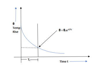
Linear function is one that changes at constant rate as exchanges. And exponential function is one that changes at the rate that always proportional to function.
Eqn. 3 is applicable to m/c which are shutdown while eqn. 2 is applicable to m/c allowed to cool owing to partial removal of load.
When t= Tc, put value of t in eqn. 3
 =0.368
 i
i
Hence, we can define cooling time constant as time taken by m/c for its temperature rise to fall 0.368 of its initial value. When cooling time constant is large, it means poor ventilation condition. When m/c cools and cooling time constant is small means good ventilation condition.
Q. A field coil has a heat dissipating surface of 0.15 m² and a length of mean turn of 1m. It dissipates loss of 150 W, the emissivity being 34 W/m² °C. Estimate final steady state temperature, rise of coil and its time constant if cross section of coil is 100×50 mm², specific heat of copper is 390 J/kg °C, the space factor is 0.56, copper weight 8900 kg/m³.
Soln. S=0.15m2
l=1m
Q=150W
 =34 W/m2oC
h = 390 J/kg oC
Wt. Of Cu = 8900 kg/m3
Cross section of coil = 100×50mm2
G=Volume×Density
Volume of Cu=1×100×50×10-6×0.56
Volume = 2.8×10⁻³ m3
Now, G=2.8×10-3×8900=24.92 kg

Heat time constant, Th = 
Q. The exciting coil of Electromagnet has a cross-section of 120×50mm² and length of mean turn of 0.8 m. It dissipates 150 Watt continuously. It cooling surface is 0.125 m² and specific heat dissipation is 30 W/m² °C. Calculate the final steady temperature rise of coil surface, also calculate hotspot temperature rise of coil if thermal resistivity of insulating material used is 8 ohms m, the space factor is 0.56.
Soln. Temp. Rise of hotspot = 

Final steady temp. Rise of coil surface
 oC
oC
Now, temp. Rise between coil surface and hotspot

Here, q = heat produced/ unit volume
t = thickness


 = resistivity of insulation

Here,  = effective resistivity of winding (i.e. material + insulation)
 thermal resistivity of insulation
Sf = Space factor
 1/2)=2 ohm m
Final temp rise of coil surface and hotspot


Temp. Rise of hotspot =  m +
m + o = 40+19.5 = 59.50C
Q. The temp rise of Xmer is 25°C after one hr and 37.5°C after two hours of starting from cold condition. Calculate its final steady temp. Rise and heating time constant. If its temp. Falls from final steady value of 40°C in 2.5 hr. When disconnected, calculate its cooling time constant. The ambient temp is 80°C
Note – Xmer starts from cold condition.
Soln.  1=25 oC
  2 = 37.5 oC
t1=1 hr t2 = 2 hrs.
Ambient temp. = 30 oC
Also, since Xmer starts from cold condition,
We use 
For 1 hr, 25  -----------------(1)
For 2 hrs., 37.5  ---------------(2)
Dividing 2 by 1
 -------------------(3)
 ,
,

1+  =1.5
=1.5
 =0.5
=0.5
Now,
25 =  (1-0.5)
 =50 0C
When cooling: cooling has started from final temp. Rise
T = 2.5 hrs
But still it is temp. Rise  =40-30 = 10 0C
 i(initial temp. Rise while cooling and final temp. Rise
  m)
m)
 i =
i =  m = 50
For cooling time,
 =
= i e-t/Tc
Tc = 1.55 hrs.
Cooling of transformer
Transformer is a static device which converts energy at one is level to another voltage level. During this process of energy transfer, losses occur in windings and core of transformer. These losses appears as heat. The heat developed in transformer is dissipated to the surrounding. The coolants used in transformer are-
1) AIR
2) Oil
The Transformer using air as coolant are called dry type transformer.
The Transformer using oil as coolant are called immersed transformer.
In dry type transformer, heat generated is conducted between Core and winding to be dissipated from outer surface of windings to surrounding air through Convection.
In case of oil immersed Transformer, the heat produced inside Core and winding is conducted across them to the surfaces. This heat is transferred by the oil to the walls of tank through Convection. Finally, the heat is transferred from tank walls to surrounding air by radiation and convection.
So, it must be understood that cooling of Transformer is different from that of rotating m/c and presents greater problem. Since there are no moving parts in transformer that are responsible for inbuilt cooling of rotating M/C.
Methods of cooling
Depending upon various parameter like capacity of Transformer, type of Transformer distribution power, etc, type of use and condition of surrounding like open place, closed room, near some equipments etc at insulation different methods are used for cooling of Transformer.
Medium used and their symbols
Air – A
Oil – O
Water – W (water does not come in contact with windings because if water enters tank contamination oil and reducing it dielectric strength)
Methods used for circulation of medium-
- Natural manner – N
- Forced manner – F
There are 2 ways of cooling a transformer-
- The coolant circulating inside the Transformer comes in contact with windings and core and transfers all the heat entirely to the tank walls from where it is dissipated to surrounding medium.
- The coolant circulating inside the Transformer comes in contact with windings and Core. The coolant partly transfer heat generated to the Transformer tank walls with major portion of heat generated inside the Transformer being taken by coolant to be dissipated away later in an external heat exchanges. The heat exchanges may employ air or water in order to dissipate heat of coolant circulated inside transformer.
Cooling Methods for Dry type Transformer
- Air Natural (AN) – This method uses ambient air cooling medium. The natural circulation of air is used to carry away heat generated by natural Convection. Generally this method is useful in small, low voltage Transformer. However use of latest insulating material like class and silicon resins which can withstand high temperature also allow use of this method for transformer up to 1.5 mva. The high rating are used in special application like Mines where fire is great hazard fire risk area, forest chemical oil and gas industry.
- Air blast (AB) - cooling by natural air circulation of air becomes inadequate to dissipate heat from last Transformer. In this method, transformer is cooled by continuous blast of cool Air forced through Core and winding. The air blast is produced by external fans, this improves the heat dissipation and reduces temp rise. The air supply must be filtered to prevent accumulation of dust particles in ventilating duct.
Cooling methods for oil immersed transformer
Oil natural (ON) or oil natural air natural (ONAN) –
The cooling by air is not so effective and proves insufficient for transformer of medium size. Oil as a coolant has two advantages.
1) It is better conductor of heat than air.
2) It has high coefficient of volume expansion with temperature therefore substantial circulation is easily obtained.
Hence, almost all Transformer except for the Transformer used for special applications like mines where there is fire hazard are oil immersed. Transformer is immersed in oil and heat generated in core and winding is passed onto oil by conduction. Oil in contact with heated part Rises and its place is taken by cool oil from bottom. The heated oil transfer its heat to tank walls from where heat is taken away to ambient air. The heated oil thereby gets cooler and falls to the bottom hence a natural thermal head (ie circulation of oil inside tank due to temperature difference) is created which transfer heat from heated part to the tank walls from where it is dissipated to surrounding air.
The tank surface is the best dissipator of heat, for small Transformer plain tank is sufficient but in case of large rating Transformer, the Transformer tank will have to be excessively large if used without any auxiliary means of heat dissipation.
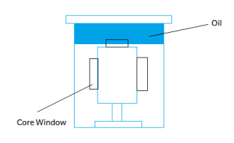
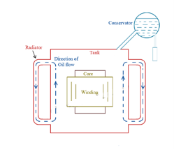
The temperature rise
Where Q = losses
S= heat dissipation area
C= cooling coefficient
So it is evident that the temperature rise can be decreased and brought within limits by two means-
i) increasing S, the area of the dissipation and
Ii) by decreasing the cooling coefficient C
Now temperature rise of transformer is inversely proportional to S, its heat dissipation area. So if size of tank is more the dissipating area is more and hence the temperature decreases.
So increasing size of Transformer tank out of proportion with increase in transformer rating and consequent increase of dimensions is obviously no solution for the temperature rise. The plain walled tank cannot be used beyond specific rating because large rating Transformer needs less volume of oil and hence it will result Higher cost and weight of Transformer. Also beyond a particular size it would be impossible to transport the Transformer from place of manufacture to site of installation.
The solution to the problem of decreasing temperature rise of large Transformer lies in decreasing C, cooling Coefficient. The value can be decreased by using auxiliary means. It should be understood that as rating of Transformer increases value of cooling Coefficient has to be decreased and this reduction in value of C can be brought out by using sophisticated methods of cooling. Therefore, as rating of Transformer increases we have to use improved methods of cooling in order to keep temperature rise within limits.
Types of constructional features of core and winding
Core- The Xmer core is closed magnetic circuit through the mutual flux i.e. the flux which links with both the winding passes.
- The core material and construction should be such that both magnetizing current and core losses are minimum
- The core of Xmer is laminated in order to reduce Eddy current losses
- Eddy current loss is proportional to the square of thickness of lamination i.e. thickness should be extremely small in order to reduce Eddy current losses to a minimum.
- The laminations are made 0.33-0.5 mm thick. The thickness should not be reduced below 0.3 mm because in that case lamination become mechanically week.
- The laminations are made of Xmer grade Steel containing 3-5% silicon. The higher content of silicon increases resistivity of core, thereby reducing the Eddy current core loss.
- The Steel used for Xmer core maybe hot rolled or cold rolled.
- Hot rolled Steel which permitted maximum flux density of 1.45 Wb/m² and flux density of cold rolled steel is up to 1.8 Wb/m² to be used (although cold rolled steel is 25 to 35% more expensive than hot rolled Steel)
CRGO steel offers following advantages:
magnetic induction is maximum and loop of BH curve is large
Core loss during no load operation is low
Reactive power at no load operation of Xmer is low.
Magnetostriction is low.
Good Mechanical properties.
Specification of 3 phase transformer as per IS 2026
IS 2026 is Indian Standard forXmer. It has 4 parts which are
Part 1 – General
Part 2- temp rise
Part 3- insulation levels and dielectric test
Part 4- Terminal marking, tapping and connection
General-
The manufacture shall ascribe rating to the Xmer transformer which shall be marked on rating plate.
Rated KVA - The rated KVA assigned shall take into account service condition and shall be related to the product of rated voltage, rated current and appropriate phase factor within the conditions defined occasional overload up to 1.5 times rated value may be allowed on Transformer with rated power upto 100 MVA.
KVA ratings-
Standard KVA rating of 3 phase transformer –
5,6.3,8,10,12.5,16.20,25,31.5,40,50,63,80,100,125,160,200,250,315,400,500,630,800,1000,etc
Rated frequency-
The frequency shall be 50Hz with tolerance of ±1%.
Following information should be provided by the manufacturer on the rating plate-
1) Number of standard (IS 2026)
2) manufacturer name
3) serial number
4) year of manufacture
5) number of phases
6) Rated KVA (for multiple winding Transformer the rated KVA of each winding shall be given)
7) rated frequency
8) Rated voltage
9) rated current
10) connection symbols
11) percent impedance voltage at rated current
12) types of cooling
13) Total mass
14) mass and volume of insulation oil
15) temperature class of insulation
16) temperature rise
17) connection diagram
18) insulation level
19) Tapping details.
Q. When initial temp. Of m/c is 45°C, calculate the temp. Of m/c after 1 hr, if final steady temp rise is 70°C and heating time constant is 2hrs. The ambient temp is 28°C.
Soln. 


Q. The initial temp of m/c is 40°C. Calculate the temp of m/c after 1 hr. If its final steady temp rise is 80°C and heating time constant is 2 hrs, ambient temperature is 30°C.
Soln. Given initial temp = 400C
Initial temp rise = 40-30 = 100C


Temp rise after 1 hr.
θ=80(1-e-1/2)+10 e-1/2
=80-70 e-1/2
θ=37.54°C
Temp of m/c after 1 hr
=37.54+30 = 67.54 0C
Space Factor
Ratio of cross sectional area of an insulated conductor to total area occupied by it.
OR
(In an electromagnetic coil). The ratio of the volume occupied by the wire in the winding or iron in core to total volume of winding or core.
Q. A 400 kVA Xmer has its max efficiency at 80% of full load. During short full load heat run, the temp rise after 1 hr and 2 hrs, it is observed to be 24°C and 34°C. Find thermal time constant and final steady temp rise of Xmer.
Soln.


(2)/(1), we get
 = +0.417
Taking natural log,

Th = 1/0.874 = 1.14 hrs.
On putting value of  in eqn
24 = 
 = 41.2oC
Q. The heat dissipating surface of 7.5 kW totally enclosed induction motor can be approximated as a cylinder of 0.6m in dia. & 0.9m in length. The motor can be considered to be made of homogenous material weighing 375 kg and having specific heat of 725 J/kg °C. The specific heat dissipation from its surface is 12 W/m² °C. Find temp rise of m/c at full load if efficiency is 90% and also find thermal time constant of machine.
Soln. Given Power o/p = 7.5kW = 7500 W
d=0.6m r=0.3m l=0.9m G=375kg h=725 J/kg oC
 W/m20C


Q. A 1000 A shunt consists of 8 strips of nickel alloy connected in parallel each having cross section of (2.5×2mm²) . The normal voltage drop is 75 mv. The alloy used has following data
Resistivity = 0.4 × 10⁻⁶ ohm m, specific heat 500 J/kg °C, specific gravity = 8000 kg/m³, rate of heat dissipation = 100 W/m² °C
Determine max temp rise and time taken to reach 99% of max value.
Soln. Ish = 1000 A
Cross sec area = 25×2 mm2 = 50 × 10-6 m2
V = 75 × 10-3 V


Let us suppose l is the length of each strip expressed in m.
Area of each strip
a = 50 mm2 = 50  10-6 m2

Now R for 8 strips in parallel

Voltage drop at shunt = 


Volume of 8 strips = 8(0.075)(50) 10-6 = 0.03
  10-3 m3
Wt. Of strip = Sp gravity  Volume
= 8000 0.03
0.03 -3 = 0.24 kg
Total heat dissipation surface
S = 8 2(l+b)h = 8
  2(2+25)
 10-6
10-6
=3.24  10-5 = 0.0324 m2
Th = 
Losses in strips
Q =  1000
1000 75
75 -3 = 75 W
Steady temp rise

As per given data, 99% of max value


Taking natural log


Q. The exciting coil of an electromagnet has a cross section of 120×50mm² and a length of mean turn 0.8m. If dissipated 150W continuously, its cooling surface is 0.125 m² and SP heat dissipation is 30 W/m² °C. Calculate steady temp rise of coil.
Soln. 
Given a = 120×50 mm2
L = 0.3m 
Q = 150 W
S = 0.125 m2
 30 W/m20C
Q. A 1527 A shunt consists of 10 strips of nickel alloy connected in parallel, each having cross sectional area 28×5 mm². The normal voltage drop is 100 mV. The alloy used following data:
Resistivity = 0.05× 10⁻⁷ ohm m
Specific heat 762 J/kg °C
Specific gravity = 7500 kg/m³.
Rate of heat dissipation = 200 W/m² °C .
Determine max terminal rise and time taken to reach 99% of max value.
Soln. 


WKT

Design can be defined physical relaxation of theoretical concept. In design of Xmer o/p, is specified by uses, voltage rating, freq., no. Of phase are given by uses. But some parameters are selected by designer like type of cooling, type of core, etc.
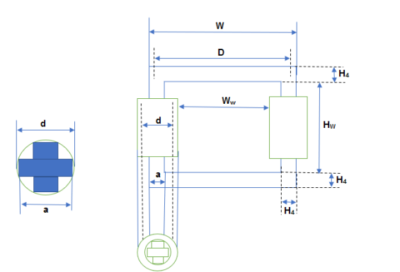
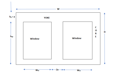
Overall heat, H = Hw + 2Hy
Overall width = D+a
Hy = a Aw = Hw.Ww
Ww = D-d
CORE CONSTRUCTION
CORE TYPE | SHELL TYPE |
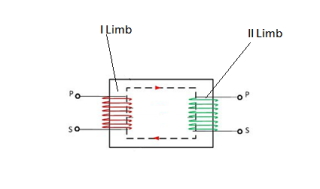 | 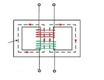 |
Consists of two limbs in which windings are there on adjust limb but in practical. Core type Xmer windings are interleaved and concentrated. Part of primary is connected on limb one and other on limb two. | Consists of 3 limbs windings at center limbs. |
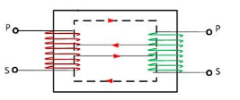 | 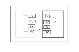 |
Because some part of flux of primary is not flowing through core and is known as leakage flux. So, in order to reduce leakage flux, we are doing this arrangement. | One over other alternatively they are interconnected or sandwich type. First IV then HV alternatively they are connected in shell type. |
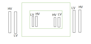 | 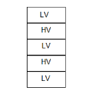 |
Practically, we wind IV first then HV to reduce insulation in core type.
Case 1: IV near to core
Let 132/33 kv Xmer.
Here, Lv = 33kV, HV = 132 kV
Here, insulation have to withstand 33kV and b/w HV and CV there is insulation and that insulation have to withstand 33kV+(132-33) = 132 kV Total
132 with standable capacity.
Case 2: HV near to core
Here, insulation has to withstand 132 kV between core and HV, after that insulation b/w HV and CV have to withstand 132+99=231 kV.
So total with standable capacity is 4 now.
To reduce insulation, we prefer lv near core.
As compared to core type, shell type has more insulation is required.
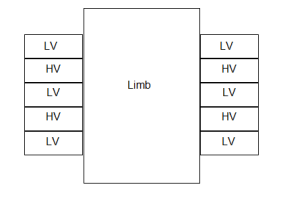
For some voltage rating insulation require in shell is more, so for HV rating we prefer core type.
So, voltage level of Xmer increase. More insulation is required. So, for HV core type Xmer is required.
Reason- HV corresponds to high flux. So, for keeping iron loss decreases, we have to use thickness core. At increased voltage we require more insulation, putting insulation is easier in core typt.
Core Type | Shell type |
HV voltage application and low current i.e low KVA rating. | Low voltage and high kVA rating. |
Windings are disturbed on 2 limbs so cooling is effected i.e. natural cooling is possible. | Cooling is bad as compared to that of core type. |
Protection of windings. | Mechanical protection is more. |
It has only one mag ckt which is simple in cons. | It has 2 mag ckt. |
|
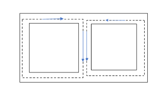
Which is difficult in cons. |
Construction of Xmer core and material
In all type of Xmer, core is constructed of sheet steel lamination to provide cont. Magnetic path with minimum of air gap included.
The steel is used is of high silicon content.
Eddy current losses is minimised by laminating the core. Laminations are insulated from each other by light coat of core plate varnish or by oxide layer on surface.
The thickness of lamination varies from 0.35-0.5 mm.
Main problem with Xmer core is
1) Hysteresis
2) Eddy current losses.
Hysteresis loss in Xmer depends on the core material.
It is found that small quantity of silicon alloyed with low carbon content steel produced material for Xmer core, which has low hysteresis loss and more permeability with less magnetising current.
With more demand on power it is required to further reduce core losses and for that more technique is employed on steel which is known as cold rolling.
This technique arranges the orientation of grain in ferromagnetic Steel in direction of rolling.
The core steel which has undergone through both Silicon alloy and cold rolling treatment is known as CRGOS or cold rolled grain oriented Silicon Steel. This is universally used for manufacturing Transformer core.
Hot rolled Steel permitted maximum flux density of 1.45 Wb/m² where as cold rolled Steel allows 1.8 Wb/m² flux density.
In both Core and shell type transformer, individual laminations are copper in form of long strips of Ls, Es and Is.
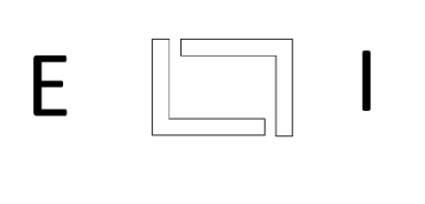
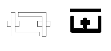
Core cross section
Small core type transformer have rectangular section limbs with rectangular coil as shown below.
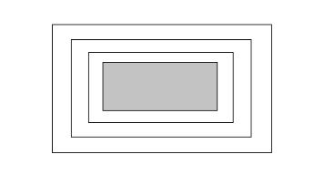
But for large size Transformer it becomes wasteful to use rectangular cylindrical coils. However economic use of Core material required cross section of core should ideally be circular. Since circle has minimum Periphery for particular area and hence winding which put around the core has minimum length of main turn resulting in reduced amount of conductor material thereby reducing cost.
But circular core however in involves use of unmanageable large number of laminations of different sizes which is possible but is highly time-consuming and also uneconomical.
Now also considerable amount of useful space is wasted. So common improvement on square core is to employ cruciform core which demands at least two sizes of core strips.
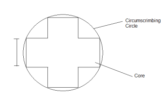
For very large Transformers for the course testing is done where at least three size of core plate are necessary.
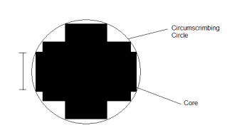
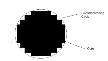
Core Stepping not only gives high space factor but also results in reduced length of mean turn and consequent power loss.
3 stepped core is one of the most commonly used all the more steps may be used for very large Transformers.
Transformer Winding
Core types-
i) Concentric
Ii) Helical
Iii) Disc
Iv) Cylindrical
v) Cross over
Shell type- sandwich type winding
Conductor, turn, coil, coul side and winding
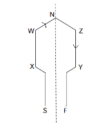
WX – conductor
ZY – conductor
End connection- VW and VZ
Coil side – VWXS and VZYF
Each single turn coil has two conductors and 2 coil sides.
End connection- The connection made to join both the conductor is called end connection.
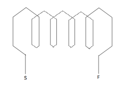
All coil sides should be in one slot in multiturn coil.
When single turn coils are connected together then it form multiturn coil.
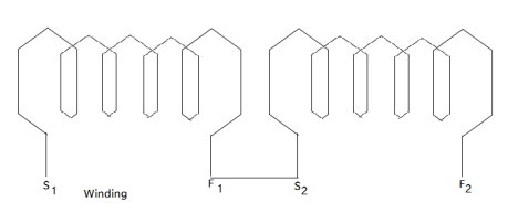
When no. Of multiturns are connected together then it forms winding.
Conductor- It is part of winding.
Conductors are placed in Armature slots.
They are responsible for inducing emf.
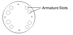
Turn – Turn consist of two conductors connected to one end by an end connection.
Multiturn coil- They are form by connecting several coils in series.
Coil- 1 turn (single turn coil)
>1 multiturn coil. In multiturn coil, there are 2T conductors.
TAP CHANGER
- Tap Changers is a device that can increase or decrease secondary voltage by changing turns ratio of primary and secondary. Either by increasing or decreasing number of turns we can change the voltage of Transformer.
- Generally, tap changes are installed on high voltage side of Transformer because at High Voltage side we get less value of current where as along low voltage side High current is there. While adjusting the tap if there is more current then it will damage the winding.
Also, High Voltage windings at outer part of Core and low voltage are at another side so it’s very easy to adjust tapping in High Voltage side.
Basic operating principle
Let us consider step down transformer.
HV - primary side
LV - secondary side.
N1 / N2 = V1 / V2
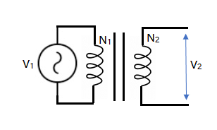
Tap Changers is on primary side so we can adjust the secondary side voltage. Since N2 will be constant and V1 is system voltage so it is also construction which we cannot change.
N1 / N2 = V1 / V2
V2 = (N2 × V1) / N1
V2 is inversely proportional to N1.
Due to frequent change and load in power system our voltage may increase or decrease beyond the limit because of which voltage regulation get affected. So in order to maintain voltage regulation we install tap changers.
No load tap changer - Now if requirements of operating secondary voltage is not very frequent i. e. Need not need to change voltage frequently then there we can use no load tap Changer. Here tap setting is changed by completely isolating the Transformer from main circuit. They are employed to distribution transformer where load is changed seasonally or occasionally.
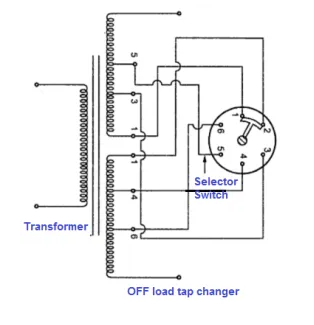
- As shown in figure, the selectro switch connects Tap 3 and 4 and so all turns in both parts of windings are in use.
- If contactor moved one point right it makes connection between 2 and 4 cutting out parts of winding between Tap 2 and 3.
- The next step connect Tap 2 and 5 and cut out part of winding between Tap 4 and 5.
This position part of winding are cut out in steps until final position which connect Type 1 and 6. This position leaves minimum number of turns in the winding.
On load tap changer - When transformer is connected to a system it is necessary that arrangement should be provided to vary the voltage on secondary side in order to maintain normal voltage under load condition. It is invariable practice to connect tapping at neutral and of High Voltage winding of transformer.
The tap changer is operated by motor operated driving mechanism by local or remote control and handle is fitted for manual operation in case of an emergency. The essential feature of an on load tap changing gear is maintenance of circuit continuity throughout tap changing operation.
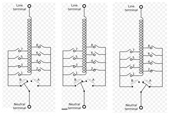
Tap changing takes place when load is on and hence in order to maintain continuity of supply to the load before one tap is left open contact must be made to next tapping.
Hence selector switch in on load tap changer is Make Before Break Switch, therefore during period of transition from one tap to other connection must be made between adjacent taps.
This connection results in short circuit of turns between adjacent typing therefore the short circuit current are limited by including resistors for reactors. In modern equipment 2 resistors are used for the purpose.
As shown in figure 1 selector switch S1 is on Tap 1 and other S2 on tap 2. The diverter switch is S3 shown connecting tap 1 tothe neutral point of Transformer.
Switching sequence for change over from tap 1 to tap 2 is –
- Contact a and b are closed. The load current flows from tap through contact b. This is running position of Tap 1
- An external mechanism moves diverted switch S3 contact b opens. The load current from tap 1 now flows through R1 and contact a.
- As moving contact of S3 continues it travels forget to left contact d closes and R1 is open circuit. But both R1 and R2 are connected across taps one and two and load current flows from tap 2 through R2 and contact d.
- When S3 moves still further to left, contact a is opened. The load current flows from tap 2 through resistance R2 and contact d.
- Finally as diverter switch S3 recharge extreme left position contact c closes and R2 is short circuited. The load current from tap 2 flows through contact a. This is running position of Tap 2
Now tap changes from 1 to 2 does not involve any movements of selector switch S1 and S2. However further tap changes from 2 to 3 is required the selector switch S1 moves to Tap 3 before the diverter switch S3 moves. The diverter switch follow sequence described above but now in reverse order.
Explosion vent- In order to guard against the possibility of sudden high pressure caused by breakdown or short circuit in transformer winding, a diaphragm relief device is used. This device consists of large opening to atmosphere covered by a thin non-metallic diaphragm.
Specification of Transformer as IS 2026 part 1.
IS 2026 is Indian standard of Transformer. It has four parts which are-
Part 1 – General
Part 2- temp rise
Part 3- insulation levels and dielectric test
Part 4- Terminal marking, tapping and connection
Standard KVA rating of 3 phase transformer –
5,6.3,8,10,12.5,16.20,25,31.5,40,50,63,80,100,125,160,200,250,315,400,500,630,800,1000,etc
Rated frequency-
The frequency shall be 50Hz with tolerance of ±1%.
Following information should be provided by the manufacturer on the rating plate-
1) Number of standard (IS 2026)
2) manufacturer name
3) serial number
4) year of manufacture
5) number of phases
6) Rated KVA (for multiple winding Transformer the rated KVA of each winding shall be given)
7) rated frequency
8) Rated voltage
9) rated current
10) connection symbols
11) percent impedance voltage at rated current
12) types of cooling
13) Total mass
14) mass and volume of insulation oil
15) temperature class of insulation
16) temperature rise
17) connection diagram
18) insulation level
19) Tapping details.
Per Unit Resistance – It is defined as resistance drop at rated current and frequency expressed at rated voltage.
Estimation of operating characteristics
Short circuit current, no load current, voltage regulation, losses, efficiency are some of the important items under estimation of operating characteristics.
Now for short circuit current estimation of winding resistance and leakage reactance is necessary.
In practical transformer, small portion of flux will link with either of the winding but not with both. This flux is known as leakage flux. Due to this leakage flux, there is self reactance in the concern windings. This self reactance is known as leakage reactance. This leakage reactance associates with resistance is known as impedance. Due to this Z, there will be voltage drop in both windings.
Resistance of windings
The value of winding resistance is required to find losses and voltage regulation.
Lmtp, Lmts length of primary and secondary windings respectively.
rp, rs Resistance of primary and secondary windings respectively.
Resistance of primary winding can be given as

Resistance of secondary winding can be given as

Total power loss in windings

Total resistance per phase of Xmer referred to primary side

And Total resistance per phase of Xmer referred to secondary side

Per unit resistance

Leakage reactance of windings
The estimation of leakage reactance is primarily the estimation of the distribution of leakage flux and the resulting flux linkages of primary and secondary windings. An exact solution of this problem is not possible.
The distribution of leakage flux depends upon the geometrical configuration of coils and the neighbouring iron masses and also permeability.
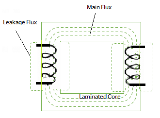
The problem of calculation of leakage flux and consequent leakage reactance is greatly simplified by making following assumptions.
1) The primary and secondary windings have an equal axial length.
2) Leakage flux paths are parallel to the windings along the axial height.
3) The MMF required for forcing the leakage flux through iron part is negligibly small therefore omitted. The MMF required is only for passing the flux through non-magnetic path. The length is assumed equal to the length of coil (winding).
The primary winding MMF Ip-Ipl is equal to secondary winding MMF (IsTs). Therefore, the magnetizing MMF and hence magnetizing current is equal to zero.
The total mmf AT =IpTp=IsTs.
Half of the leakage flux in the duct links with each winding.
Length of mean turn of windings are equal.
The reluctance of flux through yokes is negligible, therefore reluctance of Yokes does not affect the flux distribution.
The windings are uniformly distributed and therefore the windings MMF varies linearly from zero from one end to other end. (Mmf is uniformly distributed throughout the winding section).
Leakage Reactance of Core type Transformer
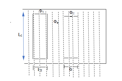
Three leakage flux paths are shown.
Let
 Leakage flux in primary and secondary windings.
 flux through duct
Lomean circumference of duct
Lcaxial height of windings
bp, bs radial width of primary and secondary winding respectively
aWidth of radial duct.
The flux leakage of windings can be found under:
a) conductor portion
b) duct portion.
Conductor portion-
Consider extremely small strip of width dx at a distance x from the edge of primary winding along its width.
Mmf acting across strip =
Permeance of strip =
Leakage flux in the strip = 
This flux links with=
Hence, flux linkage of primary due to strip =
So,


Hence flux linkages of primary winding due to flux in the strip.

Integrate both side


Duct portion-
Mmf acting across duct = IpTp
Permeance across duct =
Flux in duct= Ip Tp
Ip Tp
Duct flux linking with primary winding =  (
( Ip Tp)
Since ½ of duct flux links with primary and secondary winding respectively
= (
( Ip Tp)
Above flux links with entire primary winding.
Hence, flux linkage of primary due to duct flux

Hence, total flux linking of primary winding


Assume 

Leakage inductance of primary winding

For leakage reactance of primary winding
XL = WL =2
Xp =XL = 2
Similarly, leakage inductance of secondary winding can be calculated
Xs = = 2
Leakage reactance of secondary winding referred to primary side


Total reactance of Xmer per phase referred to primary side
Xp = Xp +Xs’

And per unit reactance

As WKT
IpTp = AT Vp/Ip = Et

In some cases-
- When transformer is on no load, all the flux produced by primary coil passes through the core. In other words, all flux produced by primary coil links with secondary coil and so there is no drop of voltage or no load.
- But when transformer is on load, because of load current flowing in both in secondary flux will produce independently by two coils. Depending upon value of current primary and secondary coil will both develop their corresponding fluxes in air. From total flux produced we have to find out which is leakage flux. It is this leakage flux which cause EMF to be induced in the coil which appears as reactive voltage drop in them.
- More the current, more is the leakage flux and so also reactive drop.
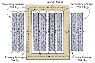
Three leakage flux paths  are shown
 leakage flux in primary and secondary winding
 flux through duet
Lo mean circumference of duet
Lc axial height of windings.
Leakage Reactance of Sandwich coils
- The idealized flux distribution in shell type transformer using sandwich coil is shown below
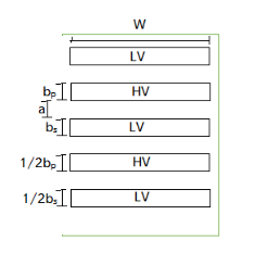
Here width of coil is taken w, analogous to axial height Lc of cylindrical
Leakage reactance of each unit referred to primary side with analogy to the cylindrical winding

Where
 =number of turns in each half coils of primary winding.
Hence, total reactance of Transformer referred to primary side


And per unit reactance

- If here are n coils in High Voltage winding then and n-1 full coils and 2 half coils in the low voltage winding.
Per unit regulation


Numerical Problems
- A 100 kVA, 2000/400 V, 50 Hz, 1 phase shell type Xmer has sandwich coils. There are 2 full HV coils, one full lv coil and 2 half lv coils. Calculate the value of leakage Reactance referred to HV side. Also calculate per unit leakage Reactance. The data given as
Depth of HV coil = 40 mm
Depth of LV coil = 36 mm
Depth of duct b/w Lv and HV = 16 mm
Width of winding = 0.12 m
Length of mean turn = 1.5 m
The no. Of turns in HV winding are 200.
Soln. Leakage reactance referred to HV side


Xp = 1.41 ohm
HV winding current at full load Ip = 
Per unit leakage reactance = 
2. A 300 kVA, 6600/400 V, 50 Hz ∆/Y 3 phase core type Xmer has following data
Width of hv winding = 25 mm, width of lv winding = 16 mm, height of coil = 0.5 m, width of duct b/w hv and lv winding = 15 mm, hv winding turns= 830 .
Calculate leakage Reactance of Xmer referred to hv side, length of mean turn = 0.9 m.
Soln. Rating = 300 kVA
Voltage ratio = 6600/400 V
f = 50 Hz
bp = 25 mm bs = 16 mm
Lc = 0.5 m a = 15 mm
Leakage reactance referred to primary side


Design of Tank with tubes
Because of losses in transformer, the temperature of Core and coil increases. In small capacity Transformer the surrounding air will be in position to cool the Transformer effectively and keep the temperature rise within the permissible limits.
But as the capacity of Transformer increases the loss and temperature rise also increases. This it is not advisable to use atmospheric air for cooling. To overcome this problem transformer is placed in steel tank filled with oil. The oil conduct heat from core and coil to the tank wall. Then heat dissipated in surrounding due to radiation and convection.
Temperature rise in pain walled tank
The walls of tank dissipates heat by both radiation and convection. It has been found experimentally that tank dissipates 6 and 6.5 w/m² °C by radiation and convection respectively. Thus, the total loss dissipation is 12.5 W/ m²°C.
Temp rise 
The surface to be considered in a formula is total area of vertical side + one half of area of cover unions oil is the contact with cover in which case whole area of lid should be taken. The area of bottom of tank should be neglected as it is very little cooling effect.
For transformer of low o/p, plain walled tank are large enough to accommodate the Transformer and oil have sufficient surface to keep temperature rise within limit. But for transformer of large o/p, plain walled tank are not sufficient to dissipate losses because increase in rating increase loss to be dissipated per unit area giving higher temperature rise.
For transformer for larger o/p must be provided with means to improve the condition of heat dissipation. This may be done by providing tubing or radiators where feasible.
Path of heat flow within Transformer by way of radiation and convection is as follows:
1) From internal most heated spot of given path i.e. winding or core to outer surface in contact with oil (heat is transferred by conduction)
2) From outer surface of given Transformer to the oil that cools it (heat is transferred by Convection of oil).
3) From coil to walls of cooler for instant of tank. (again heat is transferred by Convection of oil).
4) From walls of cooler to the cooling medium i.e. air or water (heat is dissipated by both Convection and radiation).
Temp rise and design of tank with tubes
Let dissipation surface of tank = St
It will dissipate (6+6.5) St = 12.5 St W/°C
Let area of tubes = xSt -----------------(1)
Loss dissipated by tubes by convection =1.35×6.5xSt = 8.8x St W/oC
So, total loss dissipated by tank and tubes = 12.5 St + 8.8xSt = St (12.5+8.8x) W/oC
Total area of tank and tubes = St + xSt = St (1+x)
Hence, Sp heat dissipation by tank and tubes =
Temp rise with tubes, 

Total area of tubes = xSt = 
Let lt and dt be length and dia of each tubes respectively.
So, area of each tube = 
Hence, no. Of tubes nt
Area of tube can be found by using above expression.
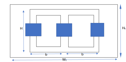
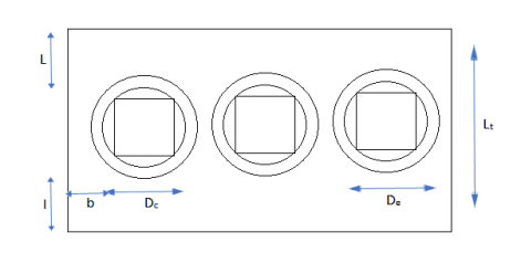
Width of tank
Wt = 2D+De+2b (for 3 phase)
= D+De+2b (for 1 phase)
Where D = distance between adjacent limbs
De = external dia of hv winding
b = clearance b/w hv winding and tank.
Length of tank Lt = De+2l
l= clearance on each side b/w winding and tank along width.
Ht. Of Xmer tank Ht = H+h
Hheight of Xmer frame
hclearance ht. b/w assembled.
Typical values of clearance b,l and h are
Voltage | Rating | Clearance B l h |
11 kV or less | Less than 10000 | 40 50 450 |
About 11KV | 1000-5000 | 70 90 420 |
Upto 33 kV | Less than 1000 1000-5000 | 75 100 550 85 125 550 |
Q. A 250 kVA, 6600/400 V, 3 phase core type transformer has total loss of 4800 W at full load. The transformer tank is 1.25 m in ht and 1m×0.5m in plan. Design a suitable scheme for tubes if average temp rise is to be limited to 35 oC. The diameter of tubes is 50 mm and are spaced 75 mm from each other. The average ht of tubes is 1.05 m.
Sp heat dissipation due to radiation and convection is respectively 6 and 6.5. Assume that convection is improved by 85% to provision of tubes.
Soln. Area of plane tank, St = 2(1+0.5)×1.25 = 3.75 m2
Let tube area be x.St
Total dissipating surface = 3.75(1+x)
Specific loss dissipation = 
From eqn of loss dissipated = 
Or x = 2.73
Area of tube = 2.73×3.75 = 10.23 m2
Wall area of each tube = 
=  = 0.165 m2
Total no of tubes = 10.23/0.165 = 62
Application of Dry type Transformer
- Chemical oil and gas industry
- Environmentally sensitive areas such as water protection area
- Fire risk area (forest)
- Inner city substation.
Disadvantage of dry type transformer
- They are long lasting with less chance of winding failure but once fails whole setup i.e. complete change of high voltage, low voltage winding with limb has to be changed.
- For same power and voltage rating dry type transformer are costlier than oil immersed because of use of insulating material like glass and silicon which has high withstand capacity.
Advantages of dry type transformer
- Safety for people pollution free solution.
- Easy installation no fire hazard
- Long lasting due to low thermal and dielectric heating.
- No temperature fluctuation high mechanical strength
- Better over load capacity.
Design of tank with tubes
1) Is the temperature rise as calculated with plane tank exceeds the specified limit, it can bring down by provision of tubes.
2) Circulation of oil is improved due to more effective hits of pressure produced by columns of oil and tube.
The provision of tubes, increasing dissipating area but increase in dissipation of heat is not proportional to area because tube screen some of tank surface preventing radiation from there. So, there is no change in surface as far as dissipation of heat due to radiation is concerned.
An addition of about 35% should be made to tube area in order to take into account this improvement in dissipation of loss by convection.
Ie 1.35×6.5
Oil Natural Air forced (ONAF)
In this method the oil circulating under Natural head transfers heat it to the tank walls. The Transformer tank is made hollow and air is blown through hollow space to cool the Transformer. The heat removed from inner tank walls can be increased to 5 or 6 tines that dissipated by natural means and therefore very large Transformer can be cooled by this method.
Oil natural water forced (ONWF)
In this method, copper cooling coil are mounted above Transformer core but below surface of oil. Water is circulated through the cooling coils to cool the Transformer. This method proves to be cheap where natural water head is already available. This method has serious disadvantage that it employs a cooling system which carries water inside the oil tank. Since water is at Higher head then oil, therefore in case of leakage water in cooling tubes will enter Transformer tank contaminating oil and reducing dielectric strength. The water inlet and outlet pipes are left in order to prevent moisture in ambient air from condensing on pipes and getting into the oil.
Forced circulation of oil (OF)
In large Transformers, natural circulation of oil is insufficient for cooling the Transformer and forced circulation is employed. Oil is circulated by motor driven pump from top of Transformer tank to an external cooling plant where oil is cooled. The cold oil enters Transformer at bottom of the tank.
Now, this method of cooling oil in heat exchangers (external cooling plant) depends upon condition obtained at the site. This method of cooling Transformer by forced circulation are classified as-
1) OFAN (oil forced air natural)
2) OFAF (oil forced air forced)
3) OFWF (oil forced water forced).
- Oil immersed Transformer of rating upto 30 KVA use plain walled tank. Above 30 KVA heat dissipating capacity of transformer is increased by providing corrugation, tubes and radiator tank.
- Transformer up to 5 mva or 50 KW use tank with tubes. The tubes are usually round and 55 mm and are arranged in one of three rows, elliptical tubes are used.
OFAN – Oil is circulated through the Transformer with the help of pump and cooled in heat exchanger by natural circulation of air. This is not commonly used. However this method proves very useful where cooler have to be well removed from transformer.
OFAF
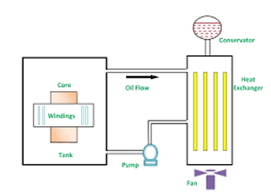
The oil is cooled in external heat exchangers using air blast produced by fan. It is interesting to note that the oil pump and fan may not be used all the time. At low loads, losses are small and hence natural circulation of oil with an ONAN condition may be sufficient to cool the Transformer.
At Higher loads, the pump and the fans may be switched on by temperature sensing elements.
Hence, Mixed cooling conditions are used, transformer working with ONAN conditions upto 50% of rating and OFAF conditions at higher loads. This arrangement results in increase of efficiency of systems.
OFWF – In this method, the heated oil is cooled in water heat exchanger. The pressure of oil is kept higher than that of water and therefore any leakage that occur is from oil to water.
This cooling method is suitable for banks of Transformer but from the system reliability consideration not more than three times should be connected in one cooling pump circuit. The advantage of OFWF method over ONWF are that the transformer is small and Transformer tank does not have to contain cooling coil carrying water. The use of water as coolant is common at generating stations, particularly hydro-electric stations where large supply of water is available. The OFWF is used for transformer design for hydroelectric plants.
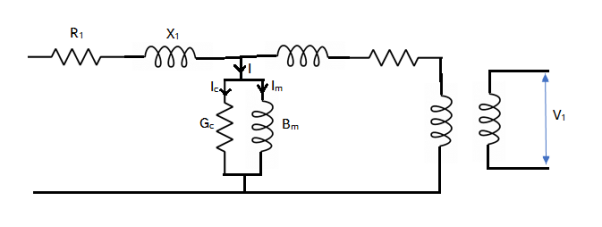
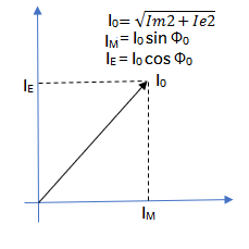
A transformer is said to be no load when its secondary winding is open circuited ie nothing is attached and Transformer loading is zero. When AC is connected to primary winding of transformer, a small current Io will flow through primary coil winding due to presence of primary supply voltage. Since secondary is open, a back EMF along with primary winding resistance act to Limit flow of this primary current. This Io (no load primary current) is made of following two components-
1) IE (in phase current) which supplies core losses (eddy current and hysteresis)
2) Im at 90° to voltage with sets up magnetic flux.
CAD/CAM is a term which means computer-aided design and computer- aided manufacturing. It is the technology concerned with the use of digital computers to perform certain functions in design and production. This technology is moving in the direction of greater integration of design and manufacturing, two activities which have traditionally been treated as distinct and separate functions in a production firm. Ultimately, CAD/CAM will provide the technology base for the computer integrated factory of the future. Computer-aided design (CAD) can be defined as the use of computer systems to assist in the creation, modification, analysis, or optimization of a design. The computer systems consist of the hardware and software to perform the specialized design functions required by the particular user firm. The CAD hardware typically includes the computer, one or more graphics display terminals, keyboards, and other peripheral equipment.
The CAD software consists of the computer programs to implement computer graphics on the system plus application programs to facilitate the engineering functions of the user company. Examples of these application programs include stress-strain analysis of components, dynamic response of mechanisms, heat-transfer calculations, and numerical control part programming. The collection of application programs will vary from one user firm to the next because their product lines, manufacturing processes, and customer markets are different. These factors give rise to differences in CAD system requirements. Computer-aided manufacturing (CAM) can be defined as the use of computer systems to plan, manage, and control the operations of a manufacturing plant through either direct or indirect computer interface with the plant's production resources.
As indicated by the definition, the applications of computer-aided manufacturing fall into two broad categories:
1. Computer monitoring and control. These are the direct applications in which the computer is connected directly to the manufacturing process for the purpose of monitoring or controlling the process.
2. Manufacturing support applications. These are the indirect applications in which the computer is used in support of the production operations in the plant, but there is no direct interface between the computer and the manufacturing process.
3 The distinction between the two categories is fundamental to a to an understanding of computer-aided manufacturing. It seems appropriate to elaborate on our brief definitions of the two types.
THE DESIGN PROCESS
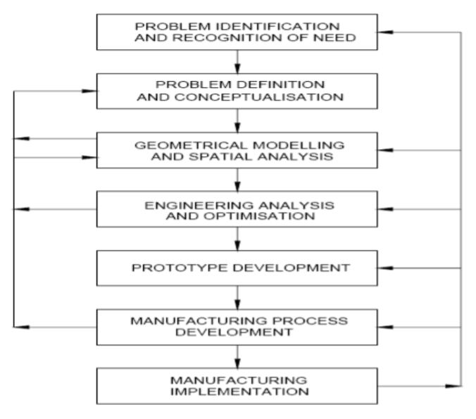
Before examining the several facets of computer-aided design, let us first consider the general design process. The process of designing something is characterized by Shigley as an iterative procedure, which consists of six identifiable steps or phases:
l. Recognition of need
2. Definition of problem
3. Synthesis
4. Analysis and optimization
Recognition of need involves the realization by someone that a problem exists for which some corrective action should be taken. This might be the identification of some defect in a current machine design by an engineer or the perception of a new product marketing opportunity by a salesperson. Definition of the problem involves a thorough specification of the item to be designed. This specification includes physical and functional characteristics, cost, quality, and operating performance.
Synthesis and analysis are closely related and highly interactive in the design process. A certain component or subsystem of the overall system is conceptualized by the designer, subjected to analysis, improved through this analysis procedure, and redesigned. The process is repeated until the design has been optimized within the constraints imposed on the designer. The components and subsystems are synthesized into the final overall system in a similar interactive manner. Evaluation is concerned with measuring the design against the specifications established in the problem definition phase. This evaluation often requires the fabrication and testing of a prototype model to assess operating performance, quality, reliability, and other criteria. The final phase in the design process is the presentation of the design.
This includes documentation of the design by means of drawings, material specifications, assembly lists, and so on. Essentially, the documentation requires that a design database be created. Figure illustrates the basic steps in the design process, indicating its iterative nature.
Engineering design has traditionally been accomplished on drawing boards, with the design being documented in the form of a detailed engineering drawing. Mechanical design includes the drawing of the complete product as well as its components and subassemblies, and the tools and fixtures required to manufacture the product. Electrical design is concerned with the preparation of circuit diagrams, specification of electronic components, and so on. Similar manual documentation is required in other engineering design fields (structural design, aircraft design, chemical engineering design, etc.). In each engineering discipline, the approach has traditionally been to synthesize a preliminary design manually and then to subject that design to some form of analysis. The analysis may involve sophisticated engineering calculations or it may involve a very subjective judgment of the aesthete appeal possessed by the design. The analysis procedure identifies certain improvements that can he made in the design. As stated previously, the process is iterative. Each iteration yields an improvement in the design. The trouble with this iterative process is that it is time consuming. Many engineering labor hours are required to complete the design project.
CAD Hardware
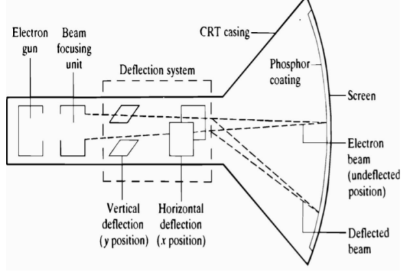
Nearly all computer graphics terminals available today use the cathode ray tube (CRT) as the display device. Television sets use a form of the same device as the picture tube. 'The operation of the CRT is illustrated in Figure. A heated cathode emits a high-speed electron beam onto a phosphor-coated glass screen. 'The electrons energize the phosphor coating, causing it to glow at the points where the beam makes contact. By focusing the electron beam, changing its intensity, and controlling its point of contact against the phosphor coating through the use of a deflector system, the beam can be made to generate a picture on the CRT screen. There are two basic techniques used in current computer graphics terminals for generating the image on the CRT screen. They are:
l. Stroke writing
2. Raster scan
Other names for the stroke-writing technique include line drawing, random position, vector writing, stroke writing, and directed beam. Other names for the raster scan technique include digital TV and scan graphics.
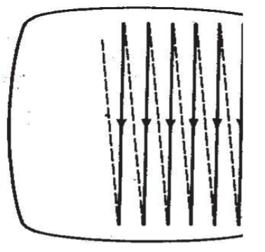
The stroke-writing system uses an electron beam which operates like a pencil to create a line image on the CRT screen. The image is constructed out of a sequence of straight-line segments. Each line segment is drawn on the screen by directing the beam to move from one point on the screen to the next, where each point is defined by its x and y coordinates. The process is portrayed in Figure . Although the procedure results in images composed of only straight lines, smooth curves can be approximated by making the connecting line segments short enough. In the raster scan approach, the viewing screen is divided into a large number of discrete phosphor picture elements, called pixels. The matrix of pixels constitutes the raster. The number of separate pixels in the raster display might typically range from 256 × 256 (a total of over 65,(OO) to lO24 × lO24 (a total of over l,OOO,OOO points). Each pixel on the screen can be made to glow with a different brightness. Color screens provide for the pixels to have different colors as well as brightness. During operation, an electron beam creates the image by sweeping along a horizontal line on the screen from left to right and energizing the pixels in that line during the sweep. When the sweep of one line is completed, the electron beam moves to the next line below and proceeds in a fixed pattern as indicated in Figure. After sweeping the entire screen the process is repeated at a rate of 3O to 6O entire scans of the screen per second:
Graphics terminals for computer-aided design
The two approaches described above are used in the overwhelming majority of current-day CAD graphics terminals. There are also a variety of other technical factors which result in different types of graphics terminals. These factors include the type of phosphor coating on the screen, whether color is required, the pixel density, and the amount of computer memory available to generate the picture. We will discuss three types of graphics terminals, which seem to be the most important today in commercially available CAD systems. The three types are:
l. Directed-beam refresh
2. Direct-view storage tube (DVST)
3. Raster scan (digital TV)
DIRECTED-BEAM REFRESH.
The directed-beam refresh terminal utilizes the stroke-writing approach to generate the image on the CRT screen. The term refresh in the name refers to the fact that the image must be regenerated many times per second in order to avoid noticeable flicker of the image. The phosphor elements on the screen surface are capable of maintaining their brightness for only a short time (sometimes measured in microseconds). In order for the image to be continued, these picture tubes must be refreshed by causing the directed beam to retrace the image repeatedly. On densely filled screens (very detailed line images or many characters of text), it is difficult to avoid flickering of the image with this process. On the other hand, there are several advantages associated with the directed- beam refresh systems. Because the image is being continually refreshed, selective erasure and alteration of the image is readily accomplished. It is also possible to provide animation of the image with a refresh tube. The directed-beam refresh system is the oldest of the modem graphics display technologies. Other names sometimes used to identify this system include vector refresh and stroke-writing refresh. Early refresh tubes were very expensive. But the steadily decreasing cost of solid-state circuitry has brought the price of these graphics systems down to a level which is competitive with other types.
DIRECT-VIEW STORAGE TUBE (DVST).
DVST terminals also use the stroke-writing approach to generate the image on the CRT screen. The term storage tube refers to the ability of the screen to retain the image which has been projected against it, thus avoiding the need to rewrite the image which has been projected against it, thus avoiding the need to rewrite the image constantly. What makes this possible is the use of an electron flood gun directed at the phosphor coated screen which keeps the phosphor elements illuminated once they have been energized by the stroke-writing electron beam. The resulting image on the CRT screen is flicker- free. Lines may be readily added to the image without concern over their effect on image density or refresh rates. However, the penalty associated with the storage tube is that individual lines cannot be selectively removed from the image. Storage tubes have historically been the lowest-cost terminals and are capable of displaying large amounts of data, either graphical or textual. Because of these features, there are probably more storage tube terminals in service in industry at the time of this writing than any other graphics display terminal. The principal disadvantage of a storage CRT is that selective erasure is not possible. Instead, if the user wants to change the picture, the change will not be manifested on the screen until the entire picture is regenerated. Other disadvantages include its lack of color capability, the inability to use a light pen as a data entry, and its lack of animation capability.
RASTER SCAN TERMINALS.
Raster scan terminals operate by causing an electron beam to trace a zigzag pattern across the viewing screen, as described earlier. The operation is similar to that of a commercial television set. The difference is that a TV set uses analog signals originally generated by a video camera to construct the image on the CRT screen, while the raster scan ICG terminal uses digital signals generated by a computer. For this reason, the raster scan terminals used in computer graphics are sometimes called digital TVs. The introduction of the raster scan graphics terminal using a refresh tube had been limited by the cost of computer memory. For example, the simplest and lowest-cost terminal in this category uses only two beam intensity levels, on or off. This means that each pixel in the viewing screen is either illuminated or dark. A picture tube with 256 lines of resolution and 256 addressable points per line to form the image would require 256 × 256 or over 65,000 bits of storage. Each bit of memory contains the on/off status of the corresponding pixel on the CRT screen. This memory is called the frame buffer or refresh buffer. The picture quality can be improved in two ways: by increasing the pixel density or adding a gray scale (or color). Increasing pixel density for the same size screen means adding more lines of resolution and more addressable points per line.
A 1024 × 1024 raster screen would require more than l million bits of storage in the frame buffer. A gray scale is accomplished by expanding the number of intensity levels which can be displayed on each pixel. This requires additional bits for each pixel to store the intensity level. Two bits are required for four levels, three bits for eight levels, and so forth. Five or six bits would be needed to achieve an approximation of a continuous gray scale. For a color display, three times as many bits are required to get various intensity levels for each of the three primary colors: red, blue, and green. (We discuss color in the following section.) A raster scan graphics terminal with high resolution and gray scale can require a very large capacity refresh buffer. Until recent developments in memory technology, the cost of this storage capacity was prohibitive for a terminal with good picture quality. The capability to achieve color and animation was notpossible except for very low resolution levels
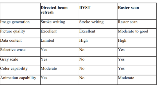
It is now possible to manufacture digital TV systems for interactive computer graphics at prices which are competitive with the other two types. The advantages of the present raster scan terminals include the feasibility to use low-cost TV monitors, color capability, and the capability for animation of the image. These features, plus the continuing improvements being made in raster scan technology, make it the fastest-growing segment of the graphics display market. The typical color CRT uses three electron beams and a triad of color dots an the phosphor screen to provide each of the three colors, red, green, and blue.
By combining the three colors at different intensity levels, a variety of colors can be created on the screen. It is mare difficult to fabricate a stroke-writing tube which is precise enough far color because of the technical problem of getting the three beams to. Converge properly against the screen. The raster scan approach has superior color graphics capabilities because of the developments which have been made over the years in the color television industry. Color raster scan terminals with 1024x1024 resolution are commercially available for computer graphics. The problem in the raster terminals is the memory requirements of the refresh buffer. Each pixel on the viewing screen' may require up to 24 bits of memory in the refresh buffer in order to display the full range of colortones. When multiplied by the number of pixels in the display screen, this translates into a very large storage buffer.
OPERATOR INPUT DEVICES
Operator input devices are provided at the graphics workstation to facilitate convenient communication between the user and the system. Workstations generally have several types of input devices to allow the operator to select the various preprogrammed input functions. These functions permit the operator to create or modify an image on the CRT screen or to enter alphanumeric data into the system. This results in a complete part on the CRT screen as well as complete geometric description of the part m the CAD data base. Different CAG system vendors offer different types of operator input devices. These devices can be divided into three general categories:
l. Cursor control devices
2. Digitizers
3. Alphanumeric and other keyboard terminals of the three, cursor control devices and digitizers are both used for graphical interaction with the system. Keyboard terminals are used as input devices for commands and numerical data.
Cursor control
The cursor normally takes the form of a bright spot on the CRT screen that, indicates where lettering or drawing will occur. The computer is capable of reading the current position of the cursor. Hence the user's capability to control the cursor position allows locational data to be entered into the CAD system data base. A typical example would be for the user to locate the cursor to identify the starting point of a line. Another, more sophisticated case, would be for the user to position the cursor to select an item from a menu of functions displayed on the screen. For instance, the screen might be divided into two sections, one of which is an array of blocks which correspond to operator input functions. The user simply moves the cursor to the desired block to execute the particular function. There are a variety of cursor control devices which have been employed in CAD systems. These include: Thumbwheels Direction keys on a keyboard terminal
Joysticks Tracker ball Light pen electronic tablet/pen
The first four items in the list provide control over the cursor without any direct physical contact of the screen by the user. The last two devices in the list require the user to control the cursor by touching the screen (or some other flat surface which is related to the screen) with a pen-type device.
The thumbwheel device uses two thumbwheels, one to control the horizontal position of the cursor, the other to control the vertical position. This type of device is often mounted as an integral part of the CRT terminal. The cursor in this arrangement is often represented by the intersection of a vertical line and a horizontal line displayed on the CRT screen. The two lines are like crosshairs in a gunsight which span the height and width of the screen. Direction keys on the keyboard are another basic form of cursor control used not only for graphics terminals but also for CRT terminals without graphics capabilities. Four keys are used for each of the four directions in which the cursor can be moved (right or left, and up or down). The joystick apparatus is pictured in Figure. It consists of a box with a vertical toggle stick that can be pushed in any direction to cause the cursor to be moved in that direction. The joystick gets its name from the control stick that was used lO old airplanes. The tracker ball is pictured in Figure. Its operation is similar to that of the joystick except that an operator-controlled ball is rotated to move the cursor in the desired direction on the screen. The light pen is a pointing device in which the computer seeks to identify
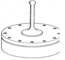
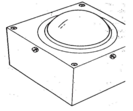
It should be noted that thumbwheels, direction keys, joysticks, and tracker balls are generally limited in their functions to cursor control. The light pen and tablet/pen are typically used for other input functions as well as cursor control
Keyboard terminals
Several forms of keyboard terminals are available as CAD input devices. The most familiar type is the alphanumeric terminal which is available with nearly all interactive graphics systems. The alphanumeric terminal can be either a CRT or a hard copy terminal, which prints on paper. For graphics, the CRT has the advantage because of its faster speed, the ability to easily edit, and the avoidance of large volumes of paper. On the other hand, a permanent record is sometimes desirable and this is most easily created with a hard-copy terminal. Many CAD systems use the graphics screen to display the alphanumeric data, but there is an advantage in having a separate CRT terminal so that the alphanumeric messages can be created without disturbing or overwriting the image on the graphics screen. The alphanumeric terminal is used to enter commands, functions, and supplemental data to the CAD system. This information is displayed for verification on the CRT or typed on paper. The system also communicates back to the user in a similar manner. Menu listings, program listings, error messages, and so forth, can be displayed by the computer as part of the interactive procedure. These function keyboards are provided to eliminate extensive typing of commands, or calculate coordinate positions, and other functions. The number of function keys varies from about 8 to 8O. The particular function corresponding with each button is generally under computer control so that the button function can be changed as the user proceeds from one phase of the design to the next. In this way the number of alternative functions can easily exceed the number of buttons on the keyboard.
PLOTTERS AND OTHER OUTPUT DEVICES There are various types of output devices used in conjunction with a computer-aided design system. These output devices include:
- Pen plotters
- Hard-copy units
- Electrostatic plotters Computer-output-to-microfilm (COM) units
We discuss these devices in the following sections.
Pen plotters
The accuracy and quality of the hard-copy plot produced by a pen plotter is considerably greater than the apparent accuracy and quality of the corresponding image on the CRT screen. In the case of the CRT image, the quality of the picture is degraded because of lack of resolution and because of losses in the digital-to-analog conversion through: the display generators. On the other hand, a high-precision pen plotter is capable of achieving a hard-copy drawing whose accuracy is nearly consistent with the digital definitions in the CAD data base. The pen plotter uses a mechanical ink pen (either wet ink or ballpoint) to write on paper through relative movement of the pen and paper. There are two basic types of pen plotters currently in use:
Drum plotters
Fiat-bed plotters
Hard-copy unit
A hard-copy unit is a machine that can make copies from the same image data layed on the CRT screen. The image on the screen can be duplicated in a matter of seconds. The copies can be used as records of intermediate steps in the design process or when rough hard copies of the screen are needed quickly. The hard copies produced from these units are not suitable as final drawings because the accuracy and quality of the reproduction is not nearly as good as the output of a pen plotter. Most hard-copy units are dry silver copiers that use light-sensitive paper exposed through a narrow CRT window inside the copier. The window is typically 8½ in. (2l6 mm), corresponding to the width of the paper, by about ½ in. (l2 mm) wide. The paper is exposed by moving it past the window and coordinating the CRT beam to gradually transfer the image. A heated roller inside the copier is used to develop the exposed paper. The size of the paper is usually limited on these hard- copy units to 8½ by II in. Another drawback is that the dry silver copies will darken with time when they are left exposed to normal light.
Electrostatic plotters
Hard-copy units are relatively fast but their accuracy and resolution are poor. Pen plotters are highly accurate but plotting time can take many minutes (up to a half-hour or longer for complicated drawings). The electrostatic plotter offers a compromise between these two types in terms of speed and accuracy. It is almost as fast as the hard-copy unit and almost as accurate as the pen plotter. The electrostatic copier consists of a series of wire styli mounted on a bar which spans the width of the charge-sensitive paper. The styli have a density of up to 2OO per linear inch. The paper is gradually moved past the bar and certain styli are activated to place dots on the paper. By coordinating the generation of the dots with the paper travel, the image is progressively transferred from the data base into hard- copy form. The dots overlap each other slightly to achieve continuity. For example, a series of adjacent dots gives the appearance of a continuous line. A limitation of the electrostatic plotter is that the data must be in the raster format (i.e., in the same format used to drive the raster-type CRT) in order to be readily converted into hard copy using the electrostatic method. If the data are not in raster format, some type of conversion is required to change them into the required format. The conversion mechanism is usually based on a combination of software and hardware. An advantage of the electrostatic plotter which is shared with the drum-type pen plotter is that the length of the paper is virtually unlimited. Typical plotting widths might be up to 6 ft (l.83 m). Another advantage is that the electrostatic plotter can be utilized as a highspeed line printer, capable of up to 1200 lines of text per minute.
References:
- K.L. Narang , A Text Book of Electrical Engineering Drawings, Reprint Edition : 1993 / 94 Satya Prakashan, New Delhi.
- A Shanmugasundaram, G. Gangadharan, R. Palani, - Electrical Machine Design Data Book, 3rd Edition, 3rd Reprint 1988 - Wiely Eastern Ltd., - New Delhi
- Vishnu Murti, “Computer Aided Design for Electrical Machines”, B.S. Publications.
- Bharat Heavy Electricals Limited, Transformers - TMH.