Unit - 2
Transformer Design: Part 2
 main flux
 Maximum flux density
 =current density
 =Gross core area
 net core area
 stacking factor *
Also known as laminate factor or space factor. It gives approximate no. Of how much core is effective when calculating flux.
. area of primary window
 area of window
D=distance between core centers or distance between center of adjacent limbs
d=diagram of circumscribing circle
 Window space factor

F=frequency
 emf [volts]
 no. Of turns in primary and secondary winding respectively
 =current in primary and secondary winding respectively
 Terminal voltage of primary and secondary
 Area of conductor of primary and secondary winding respectively
 Mean length of flux in iron
 Length of mean no. Of winding
 Weight of active iron [kg]
 Weight of copper[kg]
 Weight of per
  of iron [kg]
.
 Loss in iron per kg[w]
 Loss in cu per kg [w]
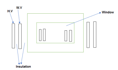
The voltage inducted in winding with T turn and excited by source having frequency ‘f’ Hz is given by considering core type. The voltage induced in  with T turns is given by E=4.44f

 4f
4f
Total CU area in window =
 Primary turn *area of primary conductor +secondary turns *area of secondary conductor
 ------2
Taking e
So
Putting  and
and  in eqn 2


Now  if we neglect magnetizing mmf
So, ----------3
As we know that
Window space factor  conductor area in window/Total area in window
 ---------------------4
Putting value of  from eqn3 to eqn 4

So, --------------5
Rating of 1 in
in  VA is given by Q=VI*
 KVA of both pri and sec is same so for
= {as Vp is approximately equal to Ep}
=
=
We know

Q=
Q=
Now, {Maximum flux density *net area of core}
SoQ=
Here winding bound over central limit so eqn for type is 
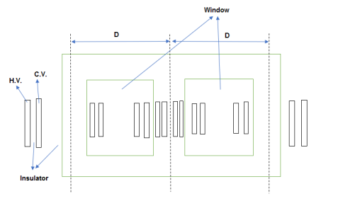
Note: In case of each 2 window consists of 2 primary and 2 sec windings
Total CU area in each window 
=
=

Now 
So 

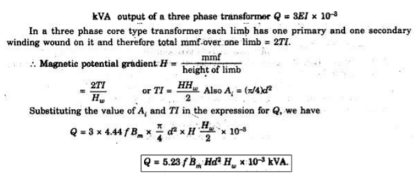
Now rating of 3 in KVA is given by
Q=
= {
{
= {
{
=
=3*
=
Q= KVA
KVA
So both the equation of Q( holds good for core and shell type
O/P equation volt per turn
Consider O/P of 1
Q= …KVA
…KVA

Q=
We know that 
So Q=
The ratio of  is constant for given type service and method of construct
Let {constant/controlling factor}
Q=
Q= =
=
So,
Here  roughly measures cross sectional of iron case AT gives cross sectional of winding so ratio of
  will be constant for
As we know that voltage per turn

=


Putting value of r=

Ratio of  depends on type service & method of construction so K also depend upon type service & method of construction.
For different type
Type K
Single phase shell type 1 to 1.2
Single phase core type 0.75to 0.85
3 shell type 1.3
3 core type (distribution) 0.45
3 core type (power) 0.6 to 0.7
Relation between core area & weight of iron &weight of w
KVA O/P of 1- is given by
Q= KVA----------------1
Now Weight of iron (G)&weight of copper (Gc) can be given as

For a specific Lets assume  ,
, are constant=c1
So, 

Where 
Putting value of  in equation -1
Q=2.22 *
*
So Area of core (Ai) can be given as
 {Mass how heavy it is }
So, ------------------2
Where C=
 ----------------3
Let 


 -------------4
Putting C in equation 2


C= Typical ratio of
  for diff are
1 core type =0.3-0.55
3 core type =0.17-0.5
1 shell type =1.2 to 2
For 3


Typical value of ratio  for different types of xmer is
1 core type =0.3 to 0.55
3 core type =0.17 to 0.5
1 core type=1.2 to 2
Calculate core and window area of 400kva,50hz .1 core type xmer. The ratio of weight of iron to cu is4.length of mean turn of cu to mean flux path
Is 0.5 maximum .flux density is 1.5 w6/ A/
A/ ,density of cu is 8.9*
 kg/
kg/ ,window space factor is 0.12
Given kVA rating =400kva ,f=50Hz

 =0.5
=0.5


Space factor=0.12
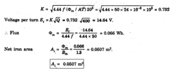
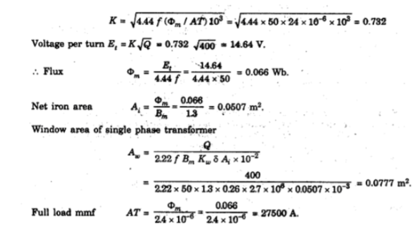
The ratio of flux to full load mmf in 400 KVA,50Hz 1
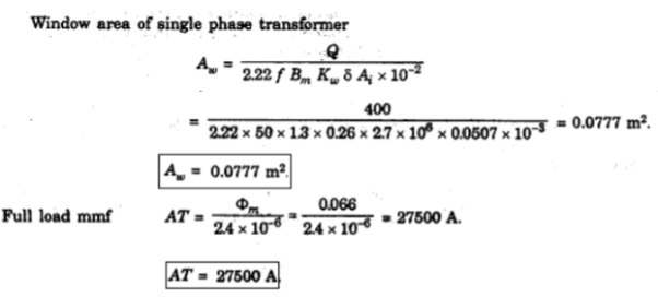
Case type is 2.4* ,Calculate net iron area &window area Maximum .flux density in the core is
  ,current density 2.4
 is 0.26.Also Calculate full load mmf

Q=400KVA
F=50Hz


We know that from O/P eqn volt per turn


We know that 

We know that


AT=27375
From

=

OPTIMUM DESIGN
May be defined to make one of the following quantities as minimum
1.total volume
2.total weight
3. Total cost
4.total losses
In general these requirement are contradictory and it is normally possible to satisfy only one of them.
All these quantities vary with ratio
Design to minimum cost.
As we know kVA o/p for 1- xmeris


Assuming  and
and  to be cons we see that for given rating
Now we know that  & also


Putting value of  &AT in eq of r

Or

Solving equations 1 &2 firstly multiply 1 & 2


Secondly put  in eq 2
As 


 Total cost of iron
 Total cost of cu or conductor


 specific cost of CU,

Putting equation 3 & 4 in equation 5

To find change of cost w.r.t 
Differentiate  w r t
w r t 

For minimum cost


 or
or 
Hence for minimum total cost the cost of iron must equal to the cost of conductor
For minimum volume

For minimum weight

For minimum losses
Iron loss  loss in conductor

DESIGN OF MINIMUM LOSS AND MAXIMUM EFFICIENCY
Total losses at full load =
At any fraction x of full load the total losses are 
If Q is O/P at full load the O/P at fraction x of full load is xQ
Efficiency at O/P x Q

For maximum efficiency


So maximum efficiency is obtained when variable losses are equal to constant loss
From ratio of iron to CU loss


DESIGN OF MAIN DIMENSIONS
Design of Core: Core is made up of several thin Lamination of 0.3-0.5mm thickness
Materials used for lamination is silicon steel which is alloy of iron & carbon
These Laminations are pile or stacked together to form core
Every Lamination is insulated by varnish or paper to reduce eddy current loss
Silicon steel used can be Hot rolled or cold rolled In recent times we use cold rolled as it has
1. High flux density
2. Reduction amount of core material used CRGO(Cold rolled grain oriented ) steel is used as core material in recent times widely
DIFFERENT TYPES OF LAMINATIONS
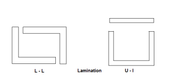
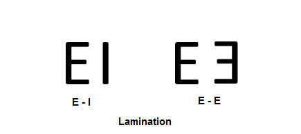
For 1 Lamination for core type & shell type are given below
Core Lamination
Shell Lamination
Stacking factor: The net cross sectional area is obtained from the dimensions of various packets & allowance is made for space lost between lamination this allowance is known as stacking factor value for sheet steel coating of insulation it becomes 0.96 
Utilization Factor: The ratio of net cross sectional area to the area of the core circle is known as utilization factor .UF increase as number of core steps increases usually optimum number of steps is 6 for smaller and 15 for larger ,this result in reduction in winding
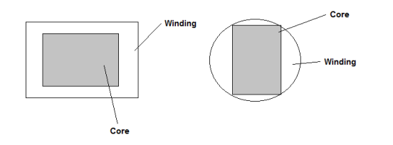
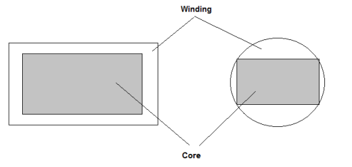
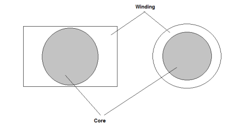
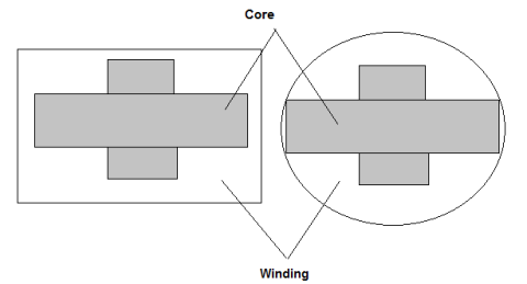
TYPES OF CORE
1 SQUARE CORE
2 RECTANGULAR CORE
3 Circular core
4 Stepped core
As circular core with circular or round conductor have uniform distribution of force and hence good mechanical strength. Hence circular core with circular conductor are more preferable than square and rectangular
Also winding put around the core have minimum length of mean turn hence reduced amount of conductor material thereby reducing the cost
A circular core however involves the unmanageably large number of Laminations of different sixes
The use of Laminations of different sizes is possible but is highly time consuming uneconomical
The corner of steps are so arranged that they lie on circle known as circumscribing circle circular coils are used because of their superior mechanical characteristic
Arrangement of core section in steps is called as stepped core or cruciform core .This involves Reduction in length of mean turn of winding
Reduction in cost of conductor material
Less  loss but involves extra cost in shearing and assembly of lamination
Rectangular Core: For moderate & small voltage power & distribution for shell type
Square & Stepped Core: For High voltage power & distributed
If square core used then diameter of circumscribing circle hence size increase Hence small diameter of circumscribing circle reduces the size & cost
CORE TYPE: Rectangular core Square Core or Stepped core
SHELL TYPE: Rectangular core
Design of Square Core
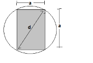
By applying Pythagoras theorem


Gross area of core


Net core area we know that

Practical value of stacking factor is 0.9


Area of circumscribing circle
 =
=
Ratio 
Hence finally
A=0.71d


U.F=0.58
2. DESIGN OF 2 STEPPED OR CRUCIFORM CORE
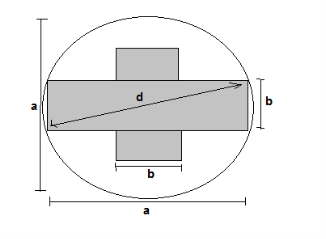
Gross core area 
Let


=
=

Differentiating the above expression w.r.t 

=
For maximum area
 =0
=0


a=dCosθ
=dCos(31.71)
=0.85d
b=0.53d


Net core area 

We can say that by increasing number of steps area of circumscribing circle is more effectively utilized finally
A=0.85d
B=0.53d


Design of yoke:
The section of yoke can be taken as rectangular or stepped
Let,
Ay =area of yoke
Area of yoke =depth of yoke *height of yoke =Dy
Oy=width of largest core stamping=a[for cruciform or stepped core]
Ay=1.5 to 1.25 times , [for using hot rolled steel]
. [for using CRGO]
Window space factor.

The window space factor [kw] depends upon the relative amounts of insulate &cu provided which in turn depends upon the voltage rating $ o/p of
The following empires formula may be used to estimate value of window space for factor [kw]
20 KVA rating: 
50-200 KVA rating =
1000 KVA rating:- 
Where,
KV:-voltage of H.V winding in kilo-volt
Window space factor is larger for large o/p and smaller for small o/p
Window dimensions:
The leakage rectangle is affected by the distance between adjacent limbs.
D decreases ww is limited .so, have increases in cow value of leakage reactance.
Hw is decreases ww results in large of reactant.
The distance is small then width of winding is limited this muses will be ultimately lead to low value of leakage reactant.
Width of window has to increases in order to accommodate coil.
The height of window is small or limited then this share and wide calls used will ultimately give rise to large value of leakage reaction
Hence area of window [AW]
Aw =total conductor area/window space factor
If considering primary side


Area of window =Height of window *width of window

Also 
The ratio of height to width of window  is 2 to 4
Assuming suitable value for ratio window  the height & width of window can be calculated
WIDTH OF WINDOW FOR OPTIMUM O/P
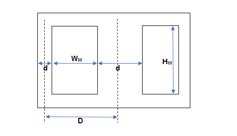
Let
D= distance between adjacent limbs
D=width of iron +width of bare conductor +width of insulation &clearance
Let m=space occupied by insulation & clearance etc.
Width occupied by CU or iron :D’=D-m
Width of bare conductor in window =D’-d
Let
S=O/P in VA in per unit height of window

Where  voltage per turn
 =turns per unit height
 =mmf per unit height
 =
=
 current density
A=area of each conductor
 =Height of conductor *width of conductor
 propor0tional to
  *width of CU in window

S=
=
Where a= constant for maximum O/P for give
n value of D’,S is differentiated w.r.t.d

For maximum O/P

D=1.5d
D=D’+m value of m can be taken as 0.2d with normal design
D=1.7d
Width of window which gives max O/P is 
Calculation of core area
Volt/turn is calculated using


K value can be selected from table
Maximum flux calculated using

Calculating net core area & Gross core area
Net core area 
Gross core area 
CHOICE OF FLUX DENSITY
->The value of flux density in the core determines the core area
->Higher values of flux density gives a smaller core area and there is a saving of cost of iron also with reduction in core area the length of mean turn of winding is also reduced thus there is saving in conductor cost also
->But with higher flux density the iron losses becomes high resulting in considerable temp. Gradient across the core. High flux density necessitates large current which contain objectionable harmonies
FLUX DENSITY VALUES
For hot rolled silicon steel:-order to keep down iron losses
Distribution ->1.1 to 1.35 
Power ->1.25 to 1.45 
Lower values should used for small rating
Cold rolled grain oriented (CRGO)
For upto 132KV->1.55
DESIGN OF WINDING
Design steps for L.V. Windings
Calculate number of turns per phase


It is fraction than it should be rounded up
For current per phase

Find cross sectional area of L.V conductor
 its value is difference for distribution small and medium power
Self coil cooled type upto 50KVA
 1.1-2.3
For large power  =2.2 to 3.2
For large power ,with forced circulation of oil or with water cooling coils
. 5.4 to 6.2 A/
Design steps for HV winding
Calculate no. Of turns per phase

=no. Pf lv turns *
.
IF +5% tapping are to be provided then no. Of turns should be increased,
Therefore ,new turns :-
Calculate H.T side current
 for 3
for 3
. for 1
for 1
Find cross section area of conductor

Note: we know how to take  value from steps of design for L.V winding
Design of Tank with tubes
Because of losses in transformer, the temperature of Core and coil increases. In small capacity Transformer the surrounding air will be in position to cool the Transformer effectively and keep the temperature rise within the permissible limits.
But as the capacity of Transformer increases the loss and temperature rise also increases. This it is not advisable to use atmospheric air for cooling. To overcome this problem transformer is placed in steel tank filled with oil. The oil conduct heat from core and coil to the tank wall. Then heat dissipated in surrounding due to radiation and convection.
Temperature rise in pain walled tank
The walls of tank dissipates heat by both radiation and convection. It has been found experimentally that tank dissipates 6 and 6.5 w/m² °C by radiation and convection respectively. Thus, the total loss dissipation is 12.5 W/ m²°C.
Temp rise 
The surface to be considered in a formula is total area of vertical side + one half of area of cover unions oil is the contact with cover in which case whole area of lid should be taken. The area of bottom of tank should be neglected as it is very little cooling effect.
For transformer of low o/p, plain walled tank are large enough to accommodate the Transformer and oil have sufficient surface to keep temperature rise within limit. But for transformer of large o/p, plain walled tank are not sufficient to dissipate losses because increase in rating increase loss to be dissipated per unit area giving higher temperature rise.
For transformer for larger o/p must be provided with means to improve the condition of heat dissipation. This may be done by providing tubing or radiators where feasible.
Path of heat flow within Transformer by way of radiation and convection is as follows:
1) From internal most heated spot of given path i.e. winding or core to outer surface in contact with oil (heat is transferred by conduction)
2) From outer surface of given Transformer to the oil that cools it (heat is transferred by Convection of oil).
3) From coil to walls of cooler for instant of tank. (again heat is transferred by Convection of oil).
4) From walls of cooler to the cooling medium i.e. air or water (heat is dissipated by both Convection and radiation).
Temp rise and design of tank with tubes
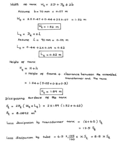
Let dissipation surface of tank = St
It will dissipate (6+6.5) St = 12.5 St W/°C
Let area of tubes = xSt -----------------(1)
Loss dissipated by tubes by convection =1.35×6.5xSt = 8.8x St W/oC
So, total loss dissipated by tank and tubes = 12.5 St + 8.8xSt = St (12.5+8.8x) W/oC
Total area of tank and tubes = St + xSt = St (1+x)
Hence, Sp heat dissipation by tank and tubes =
Temp rise with tubes, 

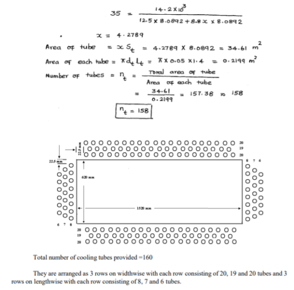
Total area of tubes = xSt = 
Let lt and dt be length and dia of each tubes respectively.
So, area of each tube = 
Hence, no. Of tubes nt
Area of tube can be found by using above expression.
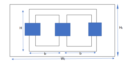
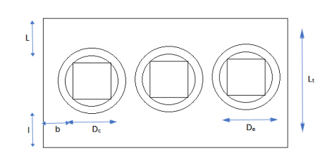
Width of tank
Wt = 2D+De+2b (for 3 phase)
= D+De+2b (for 1 phase)
Where D = distance between adjacent limbs
De = external dia of hv winding
b = clearance b/w hv winding and tank.
Length of tank Lt = De+2l
l= clearance on each side b/w winding and tank along width.
Ht. Of Xmer tank Ht = H+h
Hheight of Xmer frame
hclearance ht. b/w assembled.
Typical values of clearance b,l and h are
Voltage | Rating | Clearance B l h |
11 kV or less | Less than 10000 | 40 50 450 |
About 11KV | 1000-5000 | 70 90 420 |
Upto 33 kV | Less than 1000 1000-5000 | 75 100 550 85 125 550 |
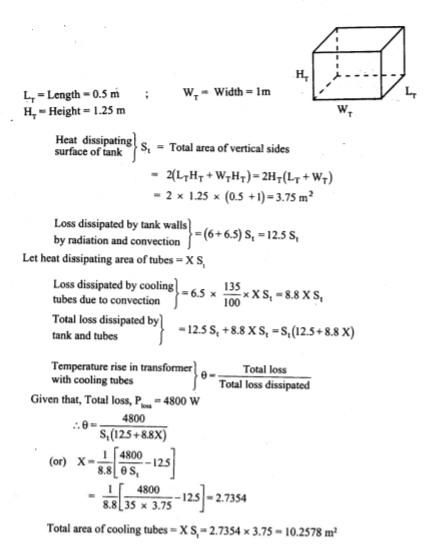
Q. A 250 kVA, 6600/400 V, 3 phase core type transformer has total loss of 4800 W at full load. The transformer tank is 1.25 m in ht and 1m×0.5m in plan. Design a suitable scheme for tubes if average temp rise is to be limited to 35 oC. The diameter of tubes is 50 mm and are spaced 75 mm from each other. The average ht of tubes is 1.05 m.
Sp heat dissipation due to radiation and convection is respectively 6 and 6.5. Assume that convection is improved by 85% to provision of tubes.
Soln. Area of plane tank, St = 2(1+0.5)×1.25 = 3.75 m2
Let tube area be x.St
Total dissipating surface = 3.75(1+x)
Specific loss dissipation = 
From eqn of loss dissipated = 
Or x = 2.73
Area of tube = 2.73×3.75 = 10.23 m2
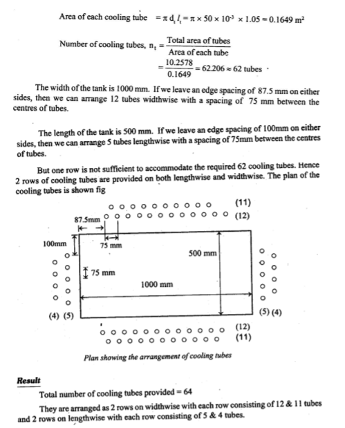
Wall area of each tube = 
=  = 0.165 m2
Total no of tubes = 10.23/0.165 = 62
Q)

A) 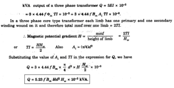
Q) 

A)
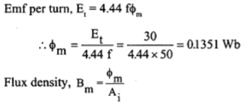

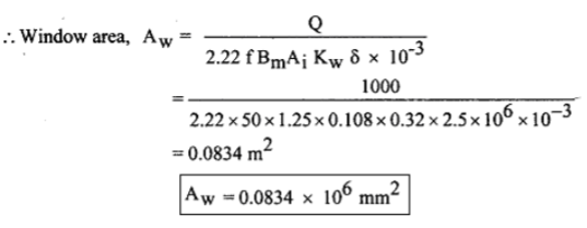
Q)

A)
Q)

A)
Q)
A)
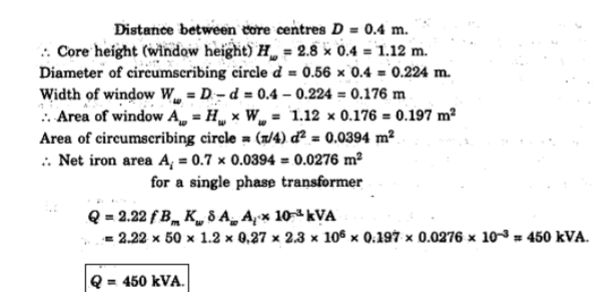
Q)

A)
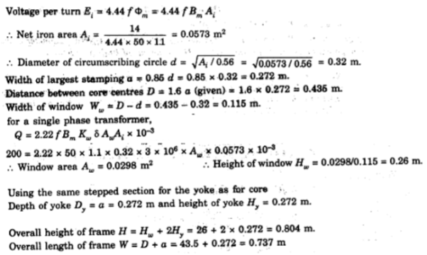
Q)
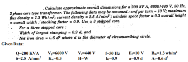
A)
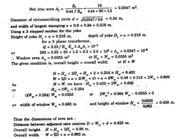
Q)

A)
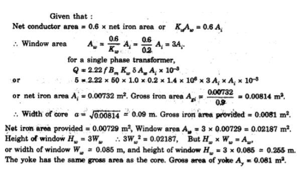
Q)

A)
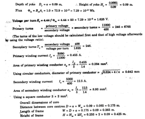
Q)

A)

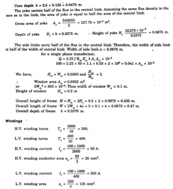
Q)

A)
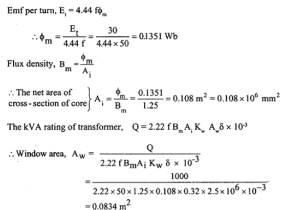

Q)

A)

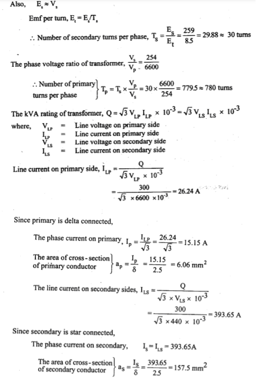
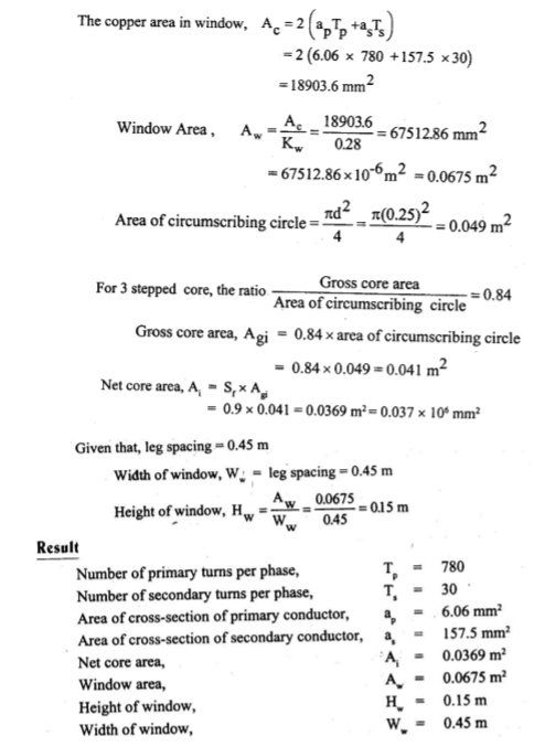
Q)

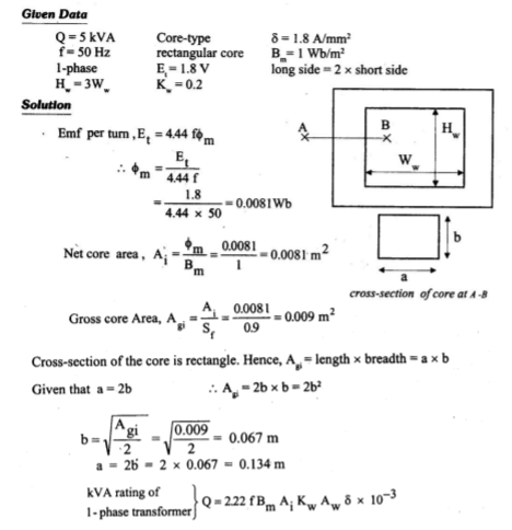
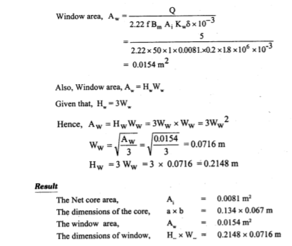
Q)
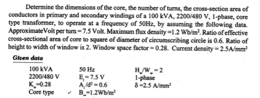
A)
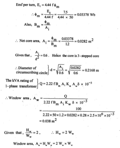

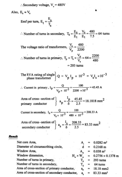
Q)
A)
Q)


A)
Q)

A)
References:
- K.L. Narang, A Text Book of Electrical Engineering Drawings, Reprint Edition: 1993 / 94 – Satya Prakashan, New Delhi.
- A Shanmugasundaram, G. Gangadharan, R. Palani, - Electrical Machine Design Data Book, 3rd Edition, 3rd Reprint 1988 - Wiely Eastern Ltd., - New Delhi
- Vishnu Murti, “Computer Aided Design for Electrical Machines”, B.S. Publications.
- Bharat Heavy Electricals Limited, Transformers - TMH.