Unit - 4
Three phase Induction Motor Design: Part1
Simple and rugged construction
Low cost and reliable
High efficiency and good power factor
Requires minimum maintenance
It is self-starting hence no special arrangement is required.
Three phase induction motor consists of stator and rotor. There are two types 3 phase induction motors:
Squirrel cage induction motor.
Phase wound induction motor.
Squirrel cage Induction motor:
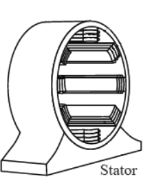
Figure 1. Stator
The stator is wound with 3 phase windings fed from a 3 phase supply. It is wound for defined number of poles, the number of poles determine from the required speed. For greater speed less no of poles are required.
When stator windings are supplied with 3 phase ac supply it produces alternating flux which revolves with synchronous speed.
The synchronous speed is inversely proportional to the number of poles (Ns = 120f/P) . This revolving or rotating magnetic field induces current in rotor winding according to Faradays law of mutual induction.
The rotor of 3 phase induction motor can be squirrel cage rotor and phase wound rotor.
Squirrel cage rotor:
Squirrel cage type rotor is simple in its construction. This type of rotor consists of cylindrical laminated core, having parallel slots on it. These parallel slots carry rotor conductors.
In this type of rotor, heavy bars of copper, aluminium or alloys are used as rotor conductors instead of wires.
Rotor slots are slightly skewed to achieve following advantages –
It reduces locking tendency of rotor that is the tendency of rotor teeth to remain under stator teeth due to magnetic attraction.
It increases effective transformation ratio between stator and rotor
It increases rotor resistance due to increased length of the rotor conductor.
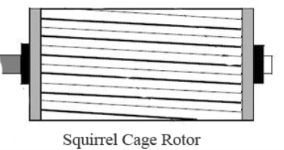
Figure 2. Squirrel Cage rotor
The rotor bars are brazed or electrically welded to short circuit the end rings at both ends. Thus, the rotor construction looks like squirrel cage. The rotor bars are permanently short circuited therefore it is not possible to add any external resistance to the armature circuit.
Phase wound rotor:
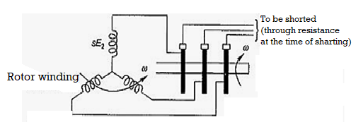
Figure 3. Phase wound rotor
Phase wound rotor
- It is wound with 3 phase, double layer, distributed winding. The number of poles of rotor are kept same as the number of poles of the stator. The rotor is always wound 3- phase even if the stator is wound two phases.
The three- phase rotor winding is internally star connected. The other three terminals of the winding are taken out through three insulated sleep rings mounted on the shaft with the brushes resting on them. - These three brushes are connected to an external star connected rheostat. This arrangement is done to introduce an external resistance in rotor circuit for starting purposes and for changing the speed / torque characteristics.
When motor is running at its rated speed, slip rings are automatically short circuited by means of a metal collar and brushes are lifted above the slip rings to minimize the frictional losses.
The ac windings for induction motors is built in one or two layers. The basic structural element is represented by lap and wave coils.
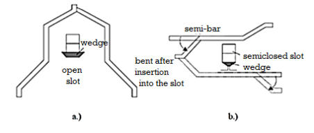
Figure 4: Bar coils: a.) continuous bar, b.) semi bar
The single turn bar coils are made of continuous bars for open bars as shown in figure for open slots or from semi-bars bent and welded together after insertion in semi-closed slots as shown in figure. These are preformed coils generally suitable for large machines.
Continuous bar coils can be made from few elementary conductors in parallel to reduce the skin effect to acceptable levels.
On the other hand, round-wire, mechanically flexible coils forced into semi-closed slots are typical for low power induction machines. Such coils have various shapes shown in figure 5.
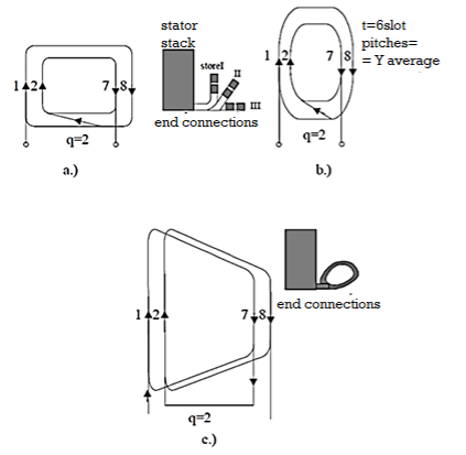
Figure 5. Full pitch coil groups/phase/pole−for q = 2−for single layer a.c. Windings
The coils for single layer windings are always full pitch as an average. These coils may be concentrated or identical. The main criteria should be to produce equal resistance and leakage inductance per phase.
The rounded concentrated or chain-shape identical coils are preferred for single layer windings. For double layer windings for low power induction machines are of trapezoidal shape and round shape wire type.
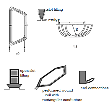
Figure 6. Typical coils for two-layer a.c. Windings:
a. Trapezoidal flexible coil (round wire);
b. Rounded flexible coil (rounded wire);
c. Preformed wound coil (of rectangular wire) for open slots.
For large power motors multi bar or uni-bar coils are used. For a.c. Windings design may be integer q or fractional q (q = a+b/c) windings with total number of slots
N = 2p1qm.
The number of slots per pole is integer. For fractional qthe latter is different and integer for phase under different poles. Only average q is fractional.
Single-layer windings are built only with an integer q.As one coil sides occupy 2 slots, it means that Ns/2m = integer (m– number of phases; m = 3 ) for single-layer windings. The number of inward current coil sides is equal to the number of outward current coil sides.
Fortwo-layer windings the allocation of slots per phase is performed in one upper layer. The second layer is occupied “automatically” by observing the coil pitch whose first side is in one layer and the second one in second layer.
In this case Ns/m = an integer.
Full pitch coil groups/phase/pole−for q = 2−for single layer a.c. Windings:
a.) with concentrated rectangular shape coils and 2 (3) store end connections.
b.) with concentrated rounded coils
c.) with chain shape coils.
A pure traveling stator mmf with an open rotor winding and a constant airgap when the stator and iron core permeability is infinite, will produce no-load ideal flux density in the airgap as
Bg10(x,t)= µ0 1gF m cosπτ x −ω1t----------(1) according to Biot – Savart law.
This flux density will self-induce sinusoidal emfs in the stator windings.
The emf induced in coil sides placed in neighboring slots are thus phase shifted by αes
αes = 2Nπps ----------------------- (2)
The number of slots with emfs in phase, t, is
t = greatest common divisor (Ns,p1) = g.c.d. (Ns,p1) ≤ p1 --------------(3)
Thus, the number of slots with emfs of distinct phase is Ns/t. Finally, the phase shift between neighboring distinct slot emfs αet is
αet =2Nπst ----------------------------------(4)
If αes = αet, that is t = p1, the counting of slots in the emf phasor star diagram is the real one in the machine.
Now consider the case of a single winding with Ns = 24, 2p1 = 4.
In this caseαes = 2Nπps 1 = 2π⋅242 = π6 -----------------------(5)
t = g.c.d. (Nsp1) = g.c.d.(24,2) = 2 = p1 --------------------------------(6)
So, the number of distinct emfs in slots is Ns/t = 24/2 = 12 and their phase shift αet = αes = π/6.
So, their counting (order) is the natural one as shown in figure 7.
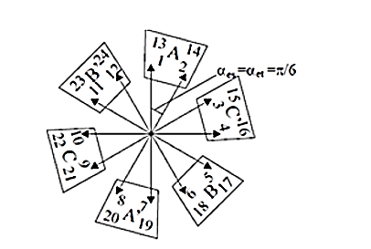
Figure 7. The star of slot emf phasors for a single-layer winding q=2,2p1=3,m=3, N1 = 24 slots
The allocation of slots of phases to produce symmetric winding is done as follows for
Single-layer windings
- Built up the slot emf phasor star based on calculating αet, αes, Ns/t distinct arrows counting them in natural order after αes.
- Choose randomly Ns/2m successive arrows to make up the inward current slots of phase A Figure7.
- The outward current arrows of phase A are shifted in phase by π radians with respect to inward current ones.
- SkipNs/2m slots from phase A, to find the slots of phase B.
- Skipfurther Ns/2m slots from phase B to find slots of phase C.
Double-layer windings
- Build the slot emf phasor star like single-layer windings.
- Choose Ns/m arrows for each phase and divide them into two groups (one for inward current sides and one for outward current sides) such that they are opposite if possible.
- The same routine is repeated for other phases providing a phase shift of 2π/3 radians between phases.
- The above rules are valid for fractional q. Fractional q windings are built in two-layers only and small qto reduce the order of first slot harmonic.
- Placing the coils in slotsfor single-layer, full pitch windings, the inward and outward side coil occupy entirely the allocated slots from left to right for each phase. There will be Ns/2m coils/phase.
- The chorded coils of double-layer windings, with a pitch y (2τ/3 ≤ y <τ for integer q and single pole count windings) are placed from left to right for each phase, with one side in one layer and other side in second layer. They are connected observing the inward (A, B, C) and outward (A’, B’, C’) directions of currents in their sides.
- Connecting the coils per phase Ns/2m coils per phase for single-layer windings and Ns/m coils per phase for double-layer windings are connected in series (or series/parallel) suchthat the first layer of the inward/outward directions are observed.
- With all coils/phase in series, we obtain a single current path (a = 1). We may obtain “a” current paths if coils from 2p1/a poles are connected in series and, then, “a ” chains in parallel.
Example
Let us design a single-layer winding with 2p1 = 2 poles, q = 4, m = 3 phases.
Solution
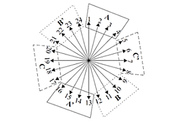
Figure 8. The star of slot emf phasors for single-layer winding q=1, 2p1=2,m=3,N1=24.
The angle αes and  are
are
αes = 2πps /N; N=24
αet =2πst /N
 = 2πP3 / N
= 2π .1 /24 = π/12
αet =2πst /N
t = g.c.d.(Ns, P1) = g.c.d. (24,1) = 1
Also, the count of distinct arrows of slot emf star Ns/t = 24/1 = 24.
Consequently, the number of arrows in the slot emf star is 24 and their order is the real (geometrical) one (1, 2, … 24) as shown in figure 8.
Making use of figure 8 we may allocate the slots to phases in Figure 9.
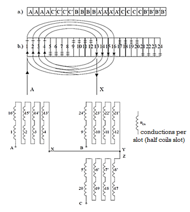
Figure 9. Single layer winding layout
a) slot/phase allocation b) rounded coils of phase A c) coils per phase
2p1 = 4, m = 3, (Ns = 2p1qm = 36 slots), chorded coils y/τ = 7/9 with a = 2 current paths.
Solution
To calculate αes, t, αet:
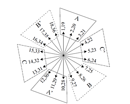
Figure 10. The star of slot emf phasors for a double-layer winding
αes = 2 = 2
= 2 2 / 36 =
  / 9.
/ 9.
t = gcd(36,2) = 2
With 2p1 = 4 poles, q=3 slots/pole/phase m=3 , Ns =36
= αes N / ts = 36/ 2 =18
There are 18 distinct arrows in the slot emf star as shown in Figure 10. The winding layout is shown in Figure 11.
We should notice the second layer slot allocation lagging by τ– y = 9 – 7 = 2 slots, the first layer allocation. Phase A produces 4 fully symmetric poles.
Also, the current paths are completely symmetric. Equipotential points of two current paths U – U’, V – V’, W – W’ could be connected to each other to handle circulating currents due to rotor eccentricity.
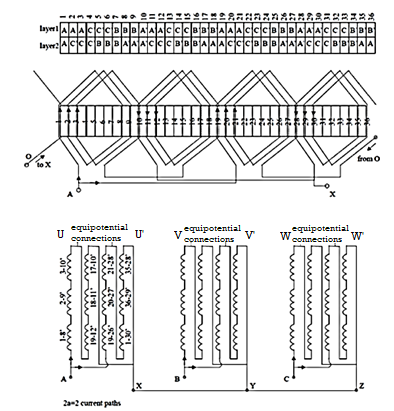
Figure 11. Double layer winding 2p1 = 4 poles, q=3, y/ = 7/9, Ns = 36 slots, a=2 current paths.
The output equation is the mathematical expression which gives the relation between various physical and electrical parameters of the electrical machine.
In induction motor the output equation is obtained as:
Consider an ‘m’ phase machine, with usual notations
Output Q in kW = Input x efficiency
Input to motor = mVph Iph cos Φ x 10-3 kW
For a 3 Φ machine
m = 3
Input to motor = 3Vph Iph cos Φ x 10-3 kW
Assuming
Vph = Eph, Vph =
Eph = 4.44 f Φ TphKw
= 2.22 f ΦZphKw
f = PNS/120 = Pns/2,
Output = 3 x 2.22 x Pns/2 x ΦZphKw Iph η cos Φ x 10-3 kW
Output = 1.11 x PΦ x 3Iph Zph x ns Kw η cos Φ x 10-3kW
PΦ = BavπDL, and 3Iph Zph/ πD = q
Output to motor = 1.11 x BavπDL x πDq x ns Kw η cos Φ x 10-3 kW
Q = (1.11 π2 Bav q Kw η cos Φ x 10-3) D2L ns kW
Q = (11 Bav q Kw η cos Φ x 10-3) D2L ns kW
Therefore, Output Q = Co D2L ns kW
Where
Co = (11 Bav q Kw η cos Φ x 10-3)
Vph = phase voltage;
Iph = phase current
Zph = no of conductors/phase
Tph = no of turns/phase
Ns = Synchronous speed in rpm
Ns = synchronous speed in rps
p = no of poles,
q = Specific electric loading
Φ = air gap flux/pole;
Bav = Average flux density
Kw = winding factor
η = efficiency cosΦ= power factor
D = Diameter of the stator,
L = Gross core length
Co = Output coefficient
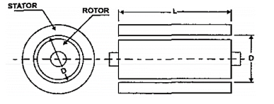
Figure 12. Dimensions of D and L
KVA input (Q) = KW/  cos Ø)
The KVA input (Q) in terms of horse power is given by:
Q = h.p x 0.746/  cos Ø
cos Ø
Specific electrical loading can be defined as the number of armature conductors per meter of armature periphery at air gap.
Specific magnetic loading :-The average flux density that is, the total magnetic loading divided by the peripheral area in the armature of a machine.
Specific magnetic loading:
The specific magnetic loading is determined by
- Maximum flux density in iron parts of the machine.
- Magnetizing current
- Core losses
Maximum flux density in iron:
The maximum flux density in any iron part of the magnetic circuit of the machine must be below a certain limiting value depending on the material used.
The flux density in air gap that is specific magnetic loading as shown by equation by
Flux density in teeth B4 = flux in each tooth / area of each tooth
Bav = ys L/Wt L = ys/Wt.-------------------(1)
In a salient pole machine, the flux is concentrated over pole arc therefore the teeth under the pole arc carry whole of the flux carried by the teeth lying outside the pole arc.
Hence, flux density in the teeth of salient pole machine is Bt = Bg/ . Ys/Wt ------------(2)
Where
Bg = maximum flux density in the air gap
 ratio of pole to pole pitch.
From equations (1) and (2) it is clear that flux density in the teeth is directly proportional to specific magnetic loading.
We have
Bt/Bav = ys/ . Bg’…………………………..(3)
Relation between the flux density in teeth and average flux density in air gap
Let us consider non-salient pole machine having S armature slots.
Flux over one slot pitch = pØ/S = p. Bav π DL/p. 1/S = Bav. π D/S L = Bav ys L
Where ye = slot pitch = π D/S
If we neglect saturation the entire flux over a slot pitch is carried by the tooth
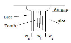
Figure 13. Flux over slot pitch
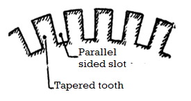
Figure 14. Armature with tapered teeth
If we neglect saturation the entire flux over a slot pitch is carried by the tooth. In a salient machine the flux is concentrated over the pole arc and therefore the teeth which are under the pole arc carry whole of the flux and hardly any flux is carried by the teeth lying outside the pole arc
Hence, flux density in the teeth of salient pole machine is Bt = Bav/Ø .ys / Wt.
But Bg = Bav/Ø
Where Bg = maximum flux density in the air gap
Ø = ratio of pole arc to pole pitch.
Magnetising current:
The magnetising current is directly proportional to the mmf required to force the flux through air gap and iron parts of the machine.
The mmf required for air gap is directly proportional to the gap flux density that is specific magnetic loading.
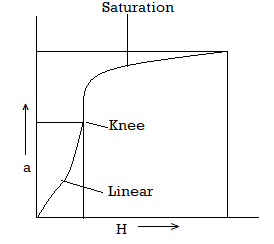
Figure 15. Relation between B-H curve
The value of flux density depends on the value of specific magnetic loading. If a small value of specific magnetic loading is chosen, the flux density in iron parts is low therefore these parts are worked on the linear or knee portion of B-H curve.
This requires small or even negligible value of mmf for iron parts as H, mmf per metre length is very small for flux densities on the linear and knee portions of the curve.
If large value of specific magnetic loading is assumed the flux density in iron parts work in the saturation region of B-H curve.
Core Loss:
The area of cross-section of iron parts of the magnetic circuit of a machine is
= flux carried by the part / flux density in the part α 1/B
If this part is subjected to alternating magnetization there will be core loss in it.
Total core loss = loss per unit volume x volume
= loss per unit volume x area x length α B2 x (1/B) α B
Thuscore loss in any part of the magnetic circuit is directly proportional to the flux density to be designed.
Specific electrical loading:
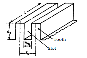
Figure 16. Slot and teeth armature of rotating machine
Permissible temperature rise:
An armature of a rotating machine is shown in figure 16. For this machine , let
Z = total number of armature conductors
S = number of armature slots
Ac = area of each conductor
 resisitivity of conductor material
 current density.
Therefore, if we consider a slot pitch ampere conductors per metre for this portion are :
 ---------------------(1)
Where Zs = Z/S = number of conductors per slot.
Resistance of slot portion of each conductor =  az-----------------(2)
I 2 R loss in slot portion of each conductor = Iz 2 Z ----------------------(3)
Therefore, I2 R loss in each slot = Zs Is 2  az -------------------------(4)
Heat produced in a slot is dissipated over the surface over one slot pitch. Considering only the cylindrical surface
Heat dissipating surface S = ys L -------------------------(5)
Loss dissipated per unit area of armature surface q = loss / surface = Zs Lz2  L/ az ys L = Iz Zs /ys . Iz/az .
  ----------------------(6)
Ac = Iz Zs/ys and  Iz/az
Iz/az
= ac  --------------------------------------(7)
Therefore heat dissipated per unit area of armature surface is proportionl to specific electric loading.
Temperature rise  = Qc /S where Q is the loss dissipated and S is the dissipation surface and c is the cooling co-efficient.
Loss dissipated per unit area q = Q/S---------------------(8)
Temperature rise  = qc = ac
  c ----------------------------------------(9)
Therefore, specific electric loading ac =  /
/  c -------------------------------------(10)
The effects of different factors are :
Temperature rise:
The spein a machine high maxicific electric loading is used when high maximum temperature is allowed. The maximum allowable temperature is determined by the type of insulating materials used.
For example organic materials like cotton, paper and varnishes may be worked upto maximum temperature. Hence, better quality insulating materials can withstand high temperature rises are used in machines.
Cooling co-efficient
From equation(10) we find that if the cooling coeffecient of the machine is small high specific electric loading may be used in the machine.
The value of cooling coeffecient c depends upon the ventilation conditions of the machine. A machine with better ventilation has lower value for cooling co-efficient and therefore high value of specific electric loading may be used due to high speed ventilation conditions.
Voltage
Area of each slot = height of slot x width of slot = ds Ws
Total area of all slots = SdsWs =  dsWs =
  ds (Ws/ys)
Therefore, total area of conductors in slts =  ds (Ws/ys) St ------------(1)
Where
Sf = space factors for slots.
Also total area of conductors (bare) = Zaz = Z Iz =
=  D ac/
D ac/  ------------------(2)
As az = Iz/ and Iz Z = =
  D ac
D ac
 D ac/
D ac/  =
=  D ds(Ws/ys) St --------------------(3)
a c = ds ds(Ws/ys) St --------------------(4)
From eq(4) for a fixed ratio of slot width to slot pitch and fixed values of depth of slot and current density the specific electric loading is directly dependent upon the space factor Sf that is the ratio of bare conductor area to total slot area.
In high voltage machines greater insulation thickness is required and space factor for these machines are lower.
Problems:
A 125W , 230V 5000rpm universal motor has a full load effeciency of 50 per cent. Calculate the power developed by a motor if the sum of the friction and winding losses is approximately 1/3 of total losses.
Solution:
Efficiency = output/ output + losses
0.5 = 125/125 + losses
Total losses = 125W and constant losses = 125/3 =42 W
Therefore, power developed by armature Pa = 125 + 42 = 167 W
The ranges of specific loadings are:
Specific magnetic loading = 0.3 to 0.6 Wb / m2
Specific electric loading = 5000 to 45000 amp.cond/m
On armature:
Each slot has two positions: top and bottom (double layer winding)
Each coil needs to occupy 2 positions: top position of one slot and bottom position of another slot.
Number of armature coils = number of armature slots (S)
M phase machine:
Number of coils per phase Sph = S/m
Number of turns per phase Nph = Sph Nc = S x Nc/m
Number of conductors per phase Cph = 2 Nph = S x Nc Xx 2 / m
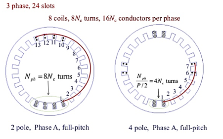
Figure 17. 2-pole, 4-pole Phase A full pitch
Slot pitch is defined by

Where  is the mechanical angle between two adjacent slots:

The slot pitch is defined as the arc length between two slots on stator inner circle(with diameter D)

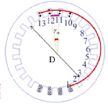

Figure 18. Three phase 2-pole Phase A full pitch.
Full-Pitch coil: If the armature coil stretches across the same angle as pole pitch it is called full-pitch coil. The coil spans across Sp slots, if Sp is an integer.
Fractional Pitch coils: If the armature coil stretches across an angle smaller than a pole pitch it is called fractional-pitch coil. The coil spans less than Sp slots.
Let Sc be the number of slots that the coil spans.
Let  = Se γm.
Coil pitch in electrical angle us defined by  P/2
P/2 
 =
=  = Sc/Sp.
The emf equation of induction motor is given by
Eph = 4.44 fØ Tph Kw-------------------(1)
Hence, the turns per phase can be obtained from emf equation Tph = Eph / 4.44 fØ Kw.
Generally, the induced emf can be to be equal to applied voltage per phase
Flux/pole = Bav x  D L / P
Winding factor kw may be assumed to be 0.955 for full pitch distributed winding unless otherwise specified.
Number conductors/phase = Zph = 2 x Tph
Hence, total number of stator conductors Z=6 Tph and conductors /slot Zs = Z/Ss or 6 Tph/Ss where Zs is an integer for single layer winding and even number for double layer winding.
In general, two types of stator slots are used in induction motors open type and semi-closed slots. Operating performance on induction motor depends on the shape of the slots and hence to select suitable slot for stator slots
Open slots: In this type the slot opening is equal to the width of the slots as shown in figure. In such type of slots assembly and repair of winding are easy. But such slots lead to higher air gap contraction factor hence there is poor power factor. These are rarely used.
Semi-closed slots: The slot opening is smaller than the width of the slot. Hence in this type of slots in assembly of windings is more difficult and takes more time compared to open slots hence it is costlier.
Tapered slots: In this type of slots opening will be much smaller than the slot width. The slot width will be varying from top of the slot to bottom of the slot with minimum width at bottom.

Figure 19. Stator slots
Selection of number of stator slots:
Number of stator slots must be properly selected at design stage such that this number affects the weight, cost and operating characteristics of motor. Though there are no rules for selecting the number of stator slots the higher number slots has to be set for selecting the number of slots.
Problem:
Q. Obtain the following design information for the stator of a 30kW, 440 V, 3 , 6 pole, 50 Hz delta connected squirrel cage induction motor.
- Main dimension of the stator
- No of turns/phase
- No of stator slots
- No of conductors per slot
Assume suitable values for the missing design data.
Specific magnetic loading Bav = 0.48 Tesla
Specific electrical loading q = 26000 ac/m
Full load efficiency η = 0.88
Full load power factor cos  = 0.86
Winding factor Kv = 0.955
Main dimension from output equation is given by:
D 2 L = Q(Co no) m 3
Co = 11 Bav q Kv η cos  x 10 -3
= 11 x 0.48 x 26000 x 0.955 x 0.88 x 0.86 x 10 -3
= 99.2
Ns = 16.67 rpm
D 2 L = 30(99.2 x 16.67) = 0.0182 m 3
Designing the machine for better power factor
D = 0.135 P 
= 0.135 x 6 
D = 0.33 m and L = 0.17 m
No of stator turns
Ø = ( /P) Bav
=  x 0.33 x 0.17 /6) x0.48 = 0.141 wb
Assuming Eph = Vph = 440 volts
Tph = Eph / 4.44 f 
= 440 / 4.44 x 50 x 0.141 x 0.955 = 148
No of stator slots
Assuming the no of slot/pole/phase = 3
Total no of slots = 3 x 3 x 6 = 54
No of conductors per slot
Total no of conductors = 148 x 2 = 296
No of conductors/slot = 296/54 = 5.5
Assuming 76 conductors/slot
Total no of conductors = 54 x 6 = 324.
Revised no of turns/phase = 162.
Problem:
Q. A 15 kW 440m volts 4 pole, 50 Hz, 3 phase induction motor is built with a stator bore of 0.25 m and a core length of 0.16 m. The specific electric loading is 23000 ac/m. Using data of this machine determine the core dimensions, number of slots and number of stator conductors for a 11kW, 460 volts,6 pole, 50 Hz motor. Assume full load efficiency of 84 % and power factor of 0.82. The winding factor is 0.955.
Sol: For 15 kW motor:
Motor Input = 15 /0.84 = 17.857 kW;
Synchronous speed ns= 120 x 50 /(4 x 60) = 25 rps;
We have output coefficient Co = out put / D2 Lns = 15 /( 0.252 x 0.16 x 25) = 60
We have Co = 11 Bav q Kw η cosΦ x 10-3 = 11 x Bav x 23000 x 0.955x 0.84 x 0.82 x 10-3 = 166.42 Bav Hence Bav = 60/166.42 = 0.36 Tesla
Pole pitch τp= π D/p = π x 0.25/4 = 0.196 m;
L/ τp = 0.815 For 11kW motor:
The design data from 15 kW machine has to be taken
So Bav = 0.36 Tesla;
q = 23000 ac/m ; L/ τp = 0.815; and C0 = 60
Synchronous speed = 120 x 50 / (6 x 60) = 16.667 rps;
D 2 L = Q/ (Co ns ) m3 = 11 / (60 x 16.667) = 0.01099 m3 L/ (π D /p) = 0.815 ,
So L/D = 0.815 x π /6 = 0.427 or L = 0.427 D
Substituting this value in D2 L product and solving for D and L 0.427 D3 = 0.01099
Hence D = 0.30 m and L = 0.125 m
Number of slots:
Considering the slot pitch at the air gap between 1.5 cm and 2.5 cm
Number of slots = π x D/ τs for slot pitch 1.5 cm,
Ss = π x 30 / 1.5 = 63
For slot pitch 2.5 cm
Ss = π x 30 / 2.5 = 37
Hence number of slots must be between 37 & 63
Assuming no. Of stator slots /pole/phase = 3,
Ss = 6 x 3 x 3 = 54
Flux per pole = Bav x D x L / p = 0.36 x π x 0.3 x 0.125/6 = 7.07 x 10⁻³ wb
Assuming star delta connection for the machine, under running condition using Delta connection Stator turns per phase Tph= Eph/ (4.44 f Kw) = 460 /(4.44 x 50 x 7.07 x 10-3 x 0.955) =307
Number conductors/phase = 307 x 2,
Total number of stator conductors = 307 x 2 x 3 =1872
Number of conductors per slot = 1872/54 = 34.1 ≈ 34
Hence, total number of conductors = 34 x 54 =1836.
Q. During the preliminary design of a 270 kW, 3600 volts, 3 phase, 8 pole 50 Hz slip ring induction motor the following design data have been obtained. Gross length of the stator core = 0.38 m, Internal diameter of the stator = 0.67 m, outer diameter of the stator = 0.86 m, No. Of stator slots = 96, No. Of conductors /slot = 12, Based on the above information determine the following design data for the motor.
(i) Flux per pole
(ii) Gap density
(iii) Conductor size
(iv) size of the slot
(v) copper losses
(vi) flux density in stator teeth
(vii) flux density in stator core.
Soln.
(i) Flux per pole Number of slots per phase 96/3 = 32 Number of turns per phase Tph = 32 x 12/2 = 192,
Assuming full pitched coils, kw = 0.955, Eph = Vph and star connected stator winding, Eph = 3600/√3 = 2078 volts,
We have Eph = 4.44fΦTphkw, ie Φ= Eph /( 4.44fTphkw) = 2078 /( 4.44 x 50 x 192 x 0.955) = 0.051wb.
(ii) Gap flux density
Ag = πDL/p = π x 0.67 x 0.38 / 8 = 0.1 m2 Bg = Φ/ Ag = 0.051/ 0.1 =0.51 Tesla
(iii) Conductor size Assuming an efficiency of 91% and a full load power factor of 0.89 Input power to the motor = 270 x 103 / 0.91 = 296703 w Full load current per phase = 296703 / ( 3 x 2078 x 0.89) = 53.47 amps Assuming a current density of 4.1 amp/mm2 , area of cross section of the conductor = 53.47 /4.1 = 13.04 mm2 as the conductor section is > 5 mm2 rectangular conductor is selected. Standard size of the conductor selected satisfying the requirements is 2.5 mm x 5.5 mm. Thus, sectional area of the conductor 13.2 mm2 Size of the conductor with insulation thickness of 0.2 mm is 2.9 mm x 5.9 mm
(iv) size of the slot 12 conductors per slot are arranged in two layers with 6 conductors in each layer. Six conductors in each layer are arranged as 2 conductors depth wise and 3 conductors width wise.
With this arrangement the width and depth of the slot can be estimated as follows.
(a) Width of the slot Space occupied by insulated conductor, 3 x 2.9 8.7 mm Coil insulation, 2 x 1.0 2.0 mm Slot liner, 2 x 0.2 0.4 mm Clearance 0.9 mm Total width of the slot 12.0 mm
(b) Depth of the slot Thus the dimension of the slot 12.0 mm x 35.0 mm
(v) Copper losses in stator winding Length of the mean turn, lmt = 2L + 2.3 τp + 0.24 = 2 x 0.38 + 2.3 x π x 0.67/8 + 0.24 = 1.6 m
Resistance per phase = (0.021 x lmt x Tph ) / as = 0.021 x 1.6 x 192 / 13.2 = 0.49 ohm.
Total copper losses = 3Is 2 rs = 3 x 53.472 x 0.49 =4203 watts
(v) Flux density in stator tooth
Diameter at 1/3rd height, D' = D + 1/3 x hts x 2 = 0.67 + 1/3 x 0.035 x 2 = 0.693 m
Slot pitch at 1/3rd height = τ ' s = π x D' /Ss = π x 0.693 /96 = 0.02268 m
Tooth width at this section = b' t = τ ' s – bs = 0.02268 – 0.012 = 0.0168 m assuming 3 ventilating ducts with 1cm width and iron space factor of 0.95 Iron length l i = ( 0.38 -3 x 0.01) 0.95 = 0.3325 m
Area of the stator tooth per pole A' t = b' t x l i x number of teeth per pole = b ' t x l i x Ss /p = 0.01068 x 0.3325 x 96/8 = 0.04261 m2
Space occupied by insulated conductor, 4 x 5.9 23.6 mm Coil insulation, 4 x 1.0 4.0 mm Slot liner, 3 x 0.2 0.6 mm
Coil separator, 1 x 1.0 0.5 mm Top liner, 1 x 1.0 0.5 mm Wedge 3.0 mm Lip 1.5 mm Clearance 1.3 mm Total height of the slot 35.0 mm Mean flux density in stator teeth B't = Φ / A' t = 0.051/ 0.04261 = 1.10 Tesla Maximum flux density in stator tooth =1.5 x 1.10 = 1.65 Tesla
(vi) Flux density in stator core
Depth of the stator core dcs = ½ ( Do- D – 2 hss) = ½ ( 0.86 - 0.67 – 2 x 0.035) = 0.06 m Area of stator core Ac = Li x dcs = 0.3325 x 0.06 = 0.01995 m2
Flux in stator core = ½ x Φ = ½ x 0.051 = 0.0255 wb
Flux density in stator core, Bc = Φc / Ac = 0.0255/ 0.01995 = 1.28 Tesla
Q. While designing the stator of a 3 phase 10 kW, 400 volts, 50 Hz, 4 pole, wound rotor induction motor, following data are obtained. Internal diameter of stator = 0.19 m Gross length = 0.125 m Number of stator slots = 36 Number of conductors/slot = 38 Dimension of stator slot = 1.1 cm x 3.5 cm Depth of the stator core = 3 cm Number of rotor slots = 30 Dimension of the rotor slot = 0.7 cm x 3.0 cm Depth of rotor core = 3.0 cm Carter’s coefficient for the air gap = 1.33 Based on the above data.
Calculate the following performance data for this motor.
i) Flux per pole
Ii) Iron losses
Iii) Active component of no load current
Iv) No load current
v) No load power factor
Soln.
i) Flux per pole Total number of stator conductors = 36 x 38 = 1368 Stator turns per phase Tph = 1368 /6 = 228 Assuming star delta connection for the motor Vph = 400 volts Assuming Eph = Vph = 400 volts, winding factor = 0.955 Air gap flux per pole Φ = Eph/(4.44fTph kw) = 400/( 4.44 x 50 x 228 x 0.955) = 0.00827 wb
Ii) Iron losses Total Iron losses = Iron losses in stator teeth + Iron losses in stator core
Iron losses in stator teeth: For the given stator length assuming one ventilating duct of width 1cm and iron space factor of 0.95,
Li = (L – nd x wd)ki = (0.125 -1 x 0.01)0.95 = 0.109 m
Diameter at 1/3rd height, D' = D + 1/3 x hts x 2 = 0.19 + 1/3 x 0.035 x 2 = 0.213 m
Slot pitch at 1/3rd height = τ ' s = π x D' /Ss = π x 0.213 /36 = 0.0186 m
Tooth width at this section = b' t = τ ' s – bs = 0.0186 – 0.011 = 0.0076 m
Area of the stator tooth per pole A' t = b' t x l i x number of teeth per pole = b' t x l i x Ss /p = 0.0076 x 0.109 x 36/4= 0.00746 m2
Mean flux density in stator teeth B't = Φ / A' t = 0.00827/ 0.00746 = 1.10 9 Tesla
Maximum flux density in stator tooth =1.5 x 1.109 = 1.66 Tesla
Volume of all the stator teeth = b' t x l i x height of teeth x number of teeth = 0.0076 x 0.109 x 0.035 x 36 = 0.001044 m3
Weight of all the teeth = volume x density Assuming a density of 7.8 x 10³ kg/ m3
Weight of all the teeth = 0.001044 x 7.8 x 103 = 8.14 kg
Total iron losses in the stator teeth = Total weight x loss/kg Iron loss in the material at a flux density of 1.66 Tesla from graph PP-22 of DDH loss/kg = 23 w/kg
Total iron losses in the stator teeth = 23 x 8.14 = 187.22 watts
Iron losses in stator core : Sectional area of the stator core = l i x dc = 0.109 x 0.03 = 0.00327 m2
Mean diameter of the stator core below the slots = 0.19 + 2 x 0.035 + 0.03 = 0.29 m
Volume of the stator core = π x D x Acs = π x 0.29 x 0.00327 = 0.002979 m3
Weight of the stator core = 0.002979 x 7.8 x 103 = 23.23 kg
Flux density in stator core = Φc / Acs = 0.00827/(2 x 0.00327) = 1.264 Tesla
At this flux density iron loss/kg = 17 watts/kg
Iron losses in the stator core = 17 x 23.23 = 394.91watts
Total iron losses in the stator = 187.22 + 394.91= 582.13 watts
Iii) Active component of no load current Assuming the friction and windage losses as 1% of output Friction and windage loss = 100 w
Total no load losses = 582.13 + 100 = 682.13 watts
Active component of no load current = Iron loss component of current Iw= Total no load losses / ( 3 x phase voltage) = 682.13/( 3 x 400) = 0.568 amps
Magnetising current: In order to calculate the magnetizing current ampere turns required for the various parts of the magnetic circuits are to be calculated.
(a) Ampere turns for the stator core: Pole pitch at he mean diameter of the stator core = π x D/ P = π x 0.29/ 4 = 0.23 m
Length of the flux path in stator core = 1/3 x 0.23 = 0.077 m
Ampere turns per meter at a flux density of 1.264 Tesla from graph (PP-22 of DDH) 400 AT
Hence total ampere turns required for the stator core = 400 x 0.077 = 31
(b) Ampere turns for the stator teeth: Length of the flux path in stator teeth = 0. 5 = 1.36 x 1.10 9 =1.508
Tesla Ampere turns per meter at a flux density of 1.508 Tesla (from graph PP-22 of DDH) is 1000 AT Hence total ampere turns for the stator teeth = 1000 x 0.035 = 35
(c) Ampere turns for the air gap: Length of the air gap = 0.2 + 2√DL = 0.2 + 2√0.19 x 0.125 = 0.51 mm
Average flux density in the air gap = Φ/ (π x DL/ P) = 0.4696
Tesla Carter’s coefficient for the air gap = 1.33
Air gap flux density at 300 from the centre of the pole Bg = 1.36 x Bav = 1.36 x 0.4696 = 0.6387 Tesla
Hence Ampere turns for the air gap = 796000Bgkglg ATg = 796000 x 0.687 x 1.33 x 0.51 x 10-3 = 371 AT
(d) Ampere turns for the rotor Teeth: Diameter of the rotor = D -2lg =0.19 – 2 x 0.00051= 0.189 m
Diameter at 1/3rd height form the narrow end of the teeth Dr ’ = D – 2 x 2/3hrs = 0.189 – 4/3 x 0.03 = 0.149 m
Slot pitch at 1/3rd height = τ ' r = π x Dr ' /Sr = π x 0.149 /30 = 0.0156 m Tooth width at this section = b' tr = τ ' r – br = 0.0156 – 0.007 = 0.0086 m
Area of the stator tooth per pole A' tr = b' tr x l i x number of teeth per pole = 0.0086 x 0.107 x 30/4 = 0.0069 m2
Flux density in rotor teeth at 300 from pole centre = 1.36 x 0.00827/0.0069 = 1.63 Tesla Ampere turns/m at this flux density, from graph (PP-22 of DDH) = 2800
Length of flux path in rotor teeth = 0.03 m Ampere turns for the rotor teeth 2800 x 0.03 = 84
(e) Ampere turns for the rotor core
Depth of the rotor core dcr = 3 cm
Area of the rotor core Acr = 0.03 x 0.107 = 0.00321 m2
Flux in the rotor = ½ x 0.00827 = 0.004135 wb
Flux density in the rotor core = 0.004135/0.00321= 1.29
Tesla Ampere turns/m at this flux density, from graph (PP-22 of DDH) = 380
Mean diameter of the rotor core = Dr – 2 x hrs – dcr = 0.189 – 2 x 0.03 – 0.03 = 0.099 m
Pole pitch at this section = π x 0.099 /4 = 0.078 m
Length of the flux path in rotor core = 1/3 x 0.078 = 0.026 m
Total ampere turns for the rotor core = 380 x 0.026 =10
Total Ampere turns for the magnetic circuit = 31 + 35 + 371 + 84 +10 = 531 AT
Magnetising current Im = p(AT30) / (1.17 x Kw x Tph) = 2 x 531 /( 1.17 x 0.955 x 228) = 4.2 amps
Iv) No load current No load current per phase Io = √( Iw 2 + Im 2 ) = √( 0.562 + 4.22 ) = 4.24 amps
v) No load power factor cos 0 = Iw/I0 = 0.56 /4.24 = 0.132
References:
- A.K Sawhney – A course in Electrical Machine Design 10th Edition – Dhanpat Rai and sons.
- Design of Electrical Machines, New age publication KG Upadhyay
- Principles of Electrical Machine Design R.K Agarwal.
- Electrical Machine Design Book by V. Rajini and V. S. Nagarajan
- Design Of Electrical Machines by Mittle V.N
.