Unit - 6
Performance parameters of Three Phase Induction Motor
Leakage flux:
Leakage flux in the induction motor takes place because the current flows through the core of the induction motor. It takes place due to the Eddy current at the core also the airgap between the stator and rotor. The mutual fluxes take place to the rotor winding by the self-fluxes as well as leakage fluxes.
As the air gap between the stator and rotor winding increases then the leakage reactance decreases and thus the leakage flux increases.
Leakage inductance:
Reactance due to rotor flux lines that do not couple with stator windings.
Reactance X2 in induction motor is equivalent circuit which represents the referred form of leakage reactance.
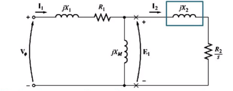
Figure 1. Leakage Inductance
The further the distance of stator from rotor bar or part of a bar the greater its leakage reactance since small percentage of rotor flux will reach the stator windings.
If the bars of the cage rotor are placed near the surface of rotor, they will have small leakage flux and X2 will be small.
If the bars of the cage rotor are placed deeper into the rotor surface, the leakage will be more and X2 is large.
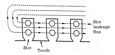
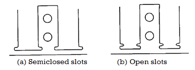
Figure 2. Slot leakage
- The flux that follows the path from tooth to tooth across the slots as shown in figure. In this process it links stator/rotor windings.
- The path of slot leakage flux is perpendicular to the main flux which passes radially down the teeth and a small potion of it straight down the slots.
- It is observed that small amount of magnetic leakage flux links bottom conductors in slots than top conductors.
- The slot leakage is dependent upon the shape of slots. It is larger in semi-closed slots used in induction machines.
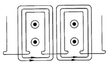
Figure 3. Tooth-tip leakage
- Leakage flux flows from the tip of one tooth to the adjacent tooth tip, surrounding all conductors. This type of flux is more in machines where airgap is larger.
- Airgap is very narrow hence tooth-tip flux is low e.g induction machine.
4.4 Zig-zag leakage:
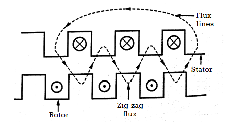
Figure 4. Zig Zag leakage
- In the case of induction machines both the stator and rotor are slotted so that some of the flux follows the path alternating between stator and rotor teeth as shown in Figure.
- This flux therefore alternately links conductors in stator and rotor slots and is known as zig-zag leakage. Because of its nature it cannot be clearly assigned to either the stator or rotor windings.
- It is considered that half of this flux links the stator winding while the other half links the rotor winding. This type of Magnetic Flux Leakage is an exclusive feature of the induction machine and its value is a function of the percentage of the slot-pitch occupied by tooth in the rotor and stator and upon the length of the air-gap.
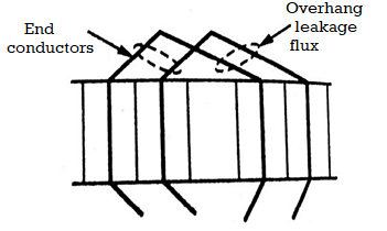
Figure 5. Overhang leakage
This is the Magnetic Leakage flux which surrounds the end conductors of the winding (stator/ rotor) as shown in Figure. Its path mainly lies through air but a part of it is in the core-iron or the iron of end shields.
The amount of this leakage depends upon the proximity of conductors and their relative location with respect to both the core and end-shields. This leakage is generally small because of the large air paths involved.
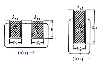
Figure 6. Effect of number of slots per pole per phase on leakage flux.
Let Zs = conductors per slot
q = slots per pole per phase
p = number of poles
Tph = turns per phase.
Consider only the slot leakage flux and leakage reactance produced due to it. In figure(a) shows the arrangement where there are 2 slots of each phase under one pole. The width of each slot is Ws , the depth of the conductor portion is h and each slot contains Zs conductors being 2Zs conductors of each phase under one pole.
The leakage is directly proportional to specific slot leakage permeance. The figure shows the slots of a phase under one pole. The conductors in slots of a phase under a pole produce leakage flux has to traverse the slots of phase under one pole.
If λs is the specific slot performance permeance the effective specific slot performance for slots of a phase under one pole is λs/q as these permeance are in series as shown in figure a. The conductors producing this leakage flux are :
T = conductors per slot x slots per pole per phase = Zsq
Reactance X = 2 f T 2 L λ
Where L = length of slot
Now for conductors of a phase under one pole T = Zs q also  =
=  / q
/ q
Therefore, slot leakage reactance of conductors of phase under one pole = 2 f (Zs q) 2 L
  s / q
s / q
= 2 f Zs2 L
  s q
s q
If the conductor of a phase under all the poles are connected in series the slot leakage reactance per phase
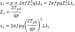

Similarly
Overhang leakage reactance per phase 
Zigzag leakage reactance per phase 
Tooth top leakage reactance per phase 
Problem:
A 3 phase 50Hz, 6 pole induction motor has 3 slots per pole per phase. The stator core length is 0.12 cm and there are 225 turns per phase in stator. Two alternative sizes of almost equal area fig(a) and (b) are available for stator slots. Calculate the stator slot leakage reactance per phase in each case and comment on the result. The machine has a single layer winding.
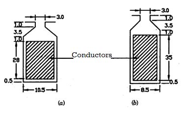
Stator slots
From fig(a)
Specific slot permeance,
λs = µo[ h1/3Ws + h2/ Ws + 2h3/Ws + Wo + h4/Wo]
= 4  x 10 -7 [ 28/ 3 x 10.5 + 1/ 10.5 + 2x3.5/10.5+3 + 1/3] = 23.1 x 10 -7 .
Stator slot leakage reactance per phase
Xs=8 f T ph 2 L ( λs / pq) = 8
 x 50 x (225)) 2 x 0.12 x 23.1 x 10 -7 / 6 x 3 = 0.98
From fig(b)
λs = 4  x 10 -7 [ 35/ 3 x 8.5 + 10.5/ 8.5 + 2x3.5/8.5+3 + 1/3] = 30.5 x 10⁻⁷
The stator leakage reactance per phase
Xs = 8 x 50 x (225)) 2 x 0.12(30.5 x 10 -7 / 6 x 3) = 1.29
The leakage reactance in case of b is higher. Thus, a deep and narrow slot gives high leakage reactance as compared with shallow and wide slot.
Problem:
A 3-phase 50 Hz alternator has parallel sided slots 0.6 m long and 20mm wide and 100 mm deep. There are 8 poles with 4 slots per phase and 10 conductors per slot.
The coils are full pitched and connected in series. Determine the leakage reactance per phase due to the slot flux.
Solution:
Height of insulation = depth of slot – height of wedge- height of conductors.
= 100 – 20 – 60 = 20mm
The insulation is 10mm at the top and 10mm at the bottom of conductors with the insulation between conductors being neglected.
Thickness of insulation is 10mm that is h2 = 10mm
It is given that h1 = height of conductor = 60mm
h3 = height of wedge = 20mm
Width of slot = width of opening that is ws = w0 = 20mm
Specific permeance of slot =
λ s = µo [ h1/3Ws + h2/Ws + 2h3/ Ws +W0)
= 4π x 10 -7 [ 60/3 x 20 + 10/20 + 2 x 20/20+20 ] = 10  x 10 -7
Total no of slots = 3 p q = 3 x 8 x 4 = 96
Total conductors = no of slots x conductors / slot = 96 x 10 = 960
Tph = z/6 = 960/6 = 160
Leakage reactance due to slot leakage
Xs = 8 f T ph 2 L ( λs / pq)
= 8 x 50 x 160 2 x 0.6 (10
  x 10 -7 / 8 x 4)
= 1.89 Ω
Usually MMF is required to overcome the reluctance of iron parts which is small as compared to mmf required for airgap.
Consider the following points:
Length of air gap is not constant over the whole pole pitch . The length of airgap at pole is more than the centre of the pole shoe. The ratio of average flux density in airgap is aclled field form factor Kf.
This ratio is approximately same as the ratio of pole pitch in dc machine.
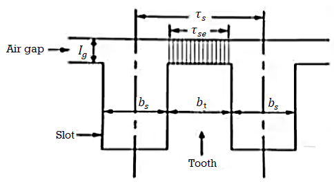
Figure 7. MMF for air gap
Kf = pole arc / pole pitch  = B av / Bmax
Therefore the effective area of air gap
Age = Gap area x field form factor
Age =  x L x Kf ; where L = gross length of armature.
Reluctance of airgap with slotted armature will be more as compared to smooth armature machines because the length of air gap will increase due to slots on the armature . This may be taken into account by considering factors for slots. The reluctance of air gap with smooth armature

Consider a slotted armature with small airgap the flux is only confined therefore effective slot pitch

Therefore the reluctance of the airgap with slotted armature .
Problem:
Calculate the mmf required for the air gap of a machine having core length = 0.32m including 4 ducts of 10mm each pole arc=0.19m ; pitch = 65.4 mm; slot opening = 5mm ; air gap length = 5mm; flux per pole = 52 m Wb. Given Carter’s co-efficient is 0.18 for opening/gap = 1 and is 0.28 opening/gap = 2.
Solution:
Ratio = slot opening/ gap length = 0.5 / 0.5 = 1
Therefore, Carter’s co-efficient for slots K gs = ys/ ys – KceWo
= 65.4 / 65.4 – 0.18 x 5 = 1.014
Ratio = duct width / gap length = 1/0.5 = 2.
Carter’s co-efficient for duct = Kcd = 0.28
Gap concentration factor duct =
Kyd = L / L – KcdmdWd = 0.32 / 0.32 – 0.28 x 4 x 1 x 10 -2 = 1.036.
Total gap concentration factor = Kv = 1.014 x 1.036 = 1.05
Flux density at the center of pole Bs = flux/pole / pole arc x core length
= 52 x 10 -3 / 0.18 x 0.32 = 0.854 Wb/m2 .
MMF required for air gap ATs = 800,00 x Kv x ls xLs
= 800,000 x 1.05 x 0.854 x 5 x 10 -3 = 3587 A
Problem:
A 175 MVA 2 pole water wheel generator has a core of length 1.72 m and diameter of 6.5 m . The stator slts have a width of 22mm , the slot pitch being 64mm and air gap length at the center of the pole is 30mm. There are 41 radial ventilating ducts each 6mm wide . The total mmf per pole is 27000A. The mmf required for the air gap is 87% of total mmf per pole. Estimate the average flux density in the air gap if the field form factor is 0.7 .
The Carter’s co-efficient can be calculated from the following relationship :
Ks = 2/ [ tan -1 y – 1/y log (1 + y2) ½ ]
Where y = Ws/lg for slots
= Wd/2 lg for ducts.
Ws,Wd are widths of slot and duct respectively and lg is the length of air gap.
Solution:
Ratio slot width / 2 (gap length) = y = 22/ 2 x 30 = 0.367.
Carter’s co-efficient for slots
Kg = ys / ys – Kav Ws = 64/64 – 0.176 x 22 = 1.1064
Ratio duct width / 2 (gap length) = y = 6 / 2 x 30 = 0.1
Carter’s co-efficient for ducts
Kcd = 2/π [ tan -1 0.1 – 1/ 0.1 [1 + 0.1 2 ] ½
= 0.05
Gap contraction factor for ducts
Kgd = L / L – Kcd nd Wd = 1720 / 1720 – 0.05 x 41 x 6 = 1.007
Total gap expansion factor = Ks = 1.1064 x 1.007 = 1.114
MMF required for air gap ATs = 0.87 x 27000 = 23490.
The calculation of MMf for teeth is due to the following :
The teeth are wedge-shaped and result in varying flux density over the length of teeth.
The teeth working as high flux density permeability is small and hence a small portion of the airgap flux is diverted and passes through the teeth less than the airgap flux.
The MMF requied for tapered teeth is calculated by the following methods:
- Graphical method
- Simpson’s rule
- Flux density at 1/3 rd section.
Graphical method :
The mmf per metre for the whole length of tooth is not uniform as the flux density is not same everywhere. Therefore, to obtain correctly the value of total mmf it is necessary to construct graph showing in manner in which ah varies over the length for the whole of the teeth.
The total mmf for the teeth is given by  dL the integrator being carried out for the complete height of tooth.
Therefore the total mmf required for the tooth,
ATs = mean ordinate x height of tooth
= atmean x I1 = atmean x ds
To determine atmean it is necessary to construct graph showing the manner in which flux density varies. From the known values of flux per tooth the flux density is evaluated for number of sections along the tooth from tip to root. The corresponding values of at from B-at curve of material are plotted. The value of atmean is obtained from graph as shown.
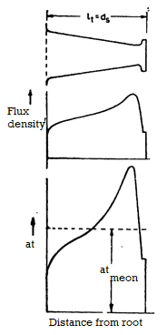
Figure 8. B-at curve tapered tooth and calculation of atmean.
Simpson’s rule:
This method is applied to teeth of simple form and of small taper and is based on the assumption that the curve relating ‘at’ with flux entity is a parabola.
In this method the vaues of at are obtained at three equidistant points , the ends of the teeth and its center.
The mean value of at is given by
Atmean = at1 + 4at2 + at3 / 6
Where at1,at2,at3 are the values of at as shown in figure.
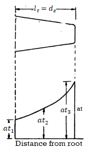
Figure 9. Calculation of atmean for tapered tooth using Simpson’s rule.
Flux density at 1/3 section. (Bt 1/3 )
This method is applied to teeth of small taper and based on the assumption that value of at is obtained for flux density at a section 1/3 of tooth height from narrow end is the mean of ‘at’ for the whole of the tooth. This method is most simple and results accurate if the teeth are worked at low saturation.
Let Bt1/3 = flux density at 1/3 height from narrow end.
At 1/3 = value of mmf per metre for Bt1/3 as obtained from B-‘at’ curve.
Total mmf for teeth At = at1/3 x lt = at1/3 x dc.
Problem:
A laminated tooth of armature steel in an electrical machine is 30mm long and has a taper such that the maximum width is 1.4 times the minimum. Estimte the mmf required for a mean flux density of 1.9 Wb/m2 in this tooth. Use Simpson’s rule .
B Wb/m3 | 1.6 | 1.8 | 1.9 | 2.0 | 2.1 | 2.2 | 2.3 |
‘at’ A/m | 3700 | 10,000 | 17,000 | 27,000 | 41,000 | 70,000 | 109,000 |
Let Wt1 , Wt2 and Wt3 be the maximum , mean and minimum widths of tooth
Wt1 = 1.4 Wt3
Wt2 = Wt1 + Wt3 /2 = 1.2 Wt3
Flux density at any section of tooth Bt = flux/tooth/ area of section
= flux/tooth ÷ net iron length x width of tooth
The flux density at any section of the tooth is inversely proportional to the tooth width .
Let Bt1,Bt2,Bt3 be the minimum,mean and maximum flux densities.
Bt1 = Bt2 Wt2/ Wt1 = 1.9 x 1.2 / 1.4 = 1.63 Wb/m2
Bt2 = 1.9 Wb/m2
Bt3 = 1.9 x 1.2 = 2.28 Wb/m2
The B-at curve is plotted in Figure. From this curve the vaues of mmf per metre for flux densities Bt1 = 1.63 Wb/m2 Bt2 = 1.9 Wb/m2 Bt3 = 2.28 Wb/m2
At1 = 4500 A at2 = 17000A and at3 = 100,500 A
Applying Simpson’s rule the mean value of mmf per metre
Atmean = at1 + 4at2 + at3 / 6
= 4500 + 4 x 17000 + 100,500/6 = 28833 A/m.
Total mmf required = atmean x l1 = 28833 x 30 x 10 -3 = 865 A
Problem:
A dc mchine has the following data :
Pole arc = 0.3 m , lengt of machine = 0.36 m , air gap = 8mm , slot pitch at the air gap surface = 25mm, slot pitch at the bottom of slots = 25mm , depth of slot = 60mm, width of slot = 12mm.
Number of ventilating ducts in armature width of each ventilating ducts flux per pole
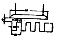
Figure 10. Details of dc machine.
Calculate :
a) Mmf required for air-gap.
b) Mmf required for teeth neglecting the slot flux.
c) Mmf required for teeth considering the slot flux.
Use B-‘at’ curve for ordinary steel plates as shown in figure. For the case of saturation refer fig band a for finding for Carter’s co-efficient .
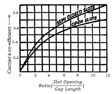
a) For Carter’s co-efficient
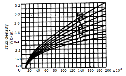
Mmf per metre ‘at’(4.16)
Gap contraction factor for slots :
Ratio slot width/ gap length = 1.2 / 0.8 = 1.5
Carter’s co-efficient from figure a corresponds to 1.5 for open slots Kav = 0.21 , Kgs = gap contraction fcator for slots
= ys/ ys – Kcs Ws = 25 / 25 – 0.21 x 12 = 1.112
Gap contraction for ducts :
Duct width = 01mm and number of ducts = 5
Ratio duct width/ gap length = 10/8 = 1.25
From fig a corressponding to 1.25 for open slots Kcd is 0.18
Gap contraction factor for ducts
Kgd = L / L – Kcd nd Wd = 0.36 / 0.36 – 0.18 x 5 x 10 x 10 -3 = 1.026
Total gap contarction factor Kg = Kgs x Kgd = 1.112 x 1.026 = 1.141
Mmf required for gap :
Assuming rectangular distribution of flux over pole arc
Form factor
Kf = 
Gap density at the centre of pole Bg = flux per pole / pole arc x length of core
= 72 x 10 -12 / 0.3 x 0.36 = 0.667 Wb /m2
MMF required for air gap = 800,000 Kq Bq Iq
= 800,000 x 1.41 x 0.667 x 8 x 10 -3 = 4870.
b) MMF required for teeth neglecting saturation.
Net iron length = K Ø(L –ndWd) = 0.9 (0.36-5x10x 10-8) = 0.279 m
No of teeth in pole arc = pole arc / tooth pitch at the gap surface = 0.3/25 x 10 -8 = 12
Tooth width at the top of slot = 25 – 12 = 13mm
Tooth width at the bottom of slot = 22 -12 = 10mm
Flux density in the tooth is maximum at the bottom as the section there is minimum calling this as Bt (mcs).
Bt (mcs) = flux per pole / number of teeeth in a pole arc x t x width of tooth at the bottom.
= 72 x 10 -3 / 12 x 0.279 x 10 x 10 -3 = 2.15 Wb/m2
The value of flux density at any height x from narrow end
Bt(x) = Bt(max) / 1 + ax
A = width at the top – width at the bottom / height of teeth = 13 -10 / 60 = 0.05
The flux density in the teeth is calculated at various sections corresponding to the value of ‘at’ taken from B -at curve . The results are tabulated as under:
Distance from the narrow and of tooth cm | Width of tooth cm | Ba99 Wb/m3 | ‘at’ A/m |
0 | 1.0 | 2.15 | 55000 |
1.0 | 1.05 | 2.05 | 35000 |
2.0 | 1.10 | 1.955 | 20000 |
3.0 | 1.15 | 1.87 | 13500 |
4.0 | 1.20 | 1.79 | 9500 |
5.0 | 1.25 | 1.72 | 7000 |
6.0 | 1.30 | 1.65 | 4750 |
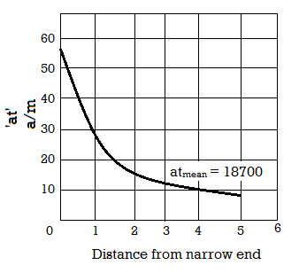
Now a graph is drawn between distance from narrow end and ‘at’. From the graph the average value of mmf per metre atmean = 18700 A/m
The total emf required for teeth = 18700 x 6 /100 = 1122 A
Simpson’s rule :
Take three equidistant sections at the top, middle and bottom of the teeth
a t 1 = 55000 at2 = 13,500 at3 = 4750
At mean = 55000 +13500 + 4750 / 6 = 18,960 A/m
Total mmf required for teeth = 18960 x 6 / 100 = 1137A
Bt1/3 method :
Flux density at 1/3 length from narrow end = 1.96 Wb/m2
At1/3 from graph = 20,000A/m
This value is higher than the value of at from graphical method. This method does not give accurate results for teeth working at saturation.
Total mmf required for teeth = 20,000 x 6/100 = 1200.
c )
Distance from the narrow end cm | Tooth area  | Tooth area   |  | Ba99 Wb/m3 | ‘at’ A/m |
0 | 27.9 | 79.2 | 2.84 | 2.15 | 37000 |
1.0 | 29.3 | 81.0 | 2.77 | 2.05 | 26000 |
2.0 | 30.7 | 82.8 | 2.7 | 1.955 | 17000 |
3.0 | 32.1 | 84.6 | 2.64 | 1.87 | 13000 |
4.0 | 33.5 | 86.4 | 2.58 | 1.79 | 9500 |
5.0 | 34.9 | 88.2 | - | 1.72 | 7000 |
6.0 | 36.3 | 90.0 | - | 1.65 | 4750 |


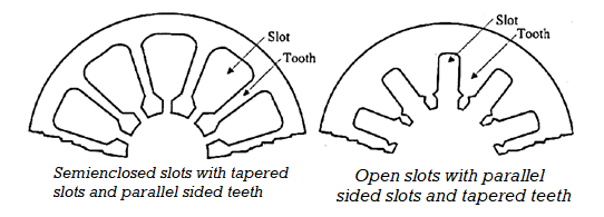
Figure 11. Stator core
When open slots are used the winding coils can be formed and fully insulated before installing & it is easier to replace the individual coils. Another advantage is that we can avoid excessive slot leakage thereby reducing the leakage reactance When semi enclosed slots are used the coils must be taped & insulated after they are placed in the slots. The advantages of semi-enclosed slots are less airgap contraction factor giving a small value of magnetising current, low tooth pulsation loss & much quieter operation. In small motors round conductors are used and in large & medium size motors strip conductors are used.
Stator core made up of laminations of thickness 0.5mm
The design of stator core involves
- Selection of number of slots,
- Estimation of dimensions of teeth
- Depth of stator core
Number stator slots depends on
1. Tooth pulsation loss
2. Leakage reactance
3. Ventilation
4. Magnetizing current
5. Iron loss
6. Cost stator slot pitch,y ss= Gap surface/Total no. Of stator slots Ss -total stator slots
Guide- lines for selecting stator slots
Step (1)-
The stator slot pitch various from 15mm to 25mm.calculate the range ofstator slots using the equation.
Stator slots Ss = πD /Yss
Minimum no of slots are obtained when Yss = 25mmMaximum no of slots are obtained when Yss= 15mm
Step (2)
Stator slots should be multiple of q where q is slot /pole / phaseSs = number of phases *poles * q
Step (3)
Select the choice of stator slots which are common between the valuesobtained in step(1) and step(2)
Step (4)
The best choice of stator slots is given by the value of slots in the listobtained from step(3) and satisfying the slot loading.
Slot loading = IzZss
Iz = current through a current
Zss = conductors per slots.
Area of stator slot
Area of each slot = Copper area per slot/space factor = Zss*as/ space factor
Space factor vary from 0.25 to 0.4After obtaining the area of the slot, the dimensions of the slot should be adjusted. The slot should not be too wide to give a thin tooth.
Stator teeth
Bts= 1.7 wb/m2 should not exceed this value
The mean flux density in stator tooth
Minimum teeth area per pole = φm/1.7
Teeth area per pole= (Ss/p)*Li*Wts
Minimum width of teeth, Wts= φm/(1.7*Ss/p*Li)
The minimum width of stator tooth is either near the gap surface or at one third height of tooth from slot opening.
Depth of stator core
Cross Section of Stator Core
Flux density lies between 1.2 to 1.5 wb/m2Flux passing through the sector core is half of the flux per pole
Flux = Фm / 2
Depth of stator coredcs= φm/(2*Bcs*Li)
Bcs = Flux density in stator core Outer diameter of stator core
Do =D+2 (depth of stator slots +depth of core)
Minimum teeth area per pole = Øm / 1.7
Teeth area per pole = (Sr/p) x Li x Wtr
Minimum width of teeth Wtr= Øm / (1.7 x Sr / p x Li)
Minimum width of teeth Wtr = [ π[Dr- 2dsr)/Sr] – Wsr
Depth of rotor core = 
Where
Bcr = flux density in rotor core
Inner diameter of rotor lamination Di = Dr -2(dsr+dcr)
Where dcr = depth of rotor core.
An electromagnetic force acts between the rotor and stator if the rotor is performing cylindrical circular whirling motion with respect to the stator. The magnetic saturation influences on the amplitude and the direction of the force. The effects of saturation is difficult to take into account analytically and the analytical models give only an approximation of the saturation effects. The effects of saturation are studied using impulse method in finite element analysis. The forces are calculated as a function of whirling frequency and supply voltage at no load and rated load. The effects are also considered from the air-gap flux density and rotor current harmonics.
The ratio of reluctance of air gap with ducts to reluctance of air gap without ducts is known as gap contraction factor for ducts.

Where L = Length of core;
Kcd = Carter’s co-efficient for ducts;
Nd = number of radial ducts;
Wd = Width of each duct
The no load current of an induction motor has two components magnetizing component, Im and iron loss component, Iw. Phase relation between these currents is shown in Figure.
Thus, the no load current
I0 = √(Im)2 + (Iw)2 amps
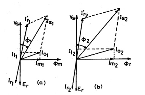
Fig 12. Phasor diagram of induction motor
Magnetising current: Magnetising current of an induction motor produces the required amount of flux in the different parts of the machine. Hence this current can be calculated from all the magnetic circuit of the machine. The ampere turns for all the magnetic circuit such as stator core, stator teeth, air gap, rotor core and rotor teeth give the total ampere turns required for the magnetic circuit. Based on the total ampere turns of the magnetic circuit the magnetizing current can be calculated as
Magnetising current Im= p AT30 / (1.17 kw Tph )
Where p – no of pairs of poles, AT30 – Total ampere turns of the magnetic circuit at 300 from the centre of the pole, Tph – Number of stators turns per phase.
Iron loss component of current: This component of current is responsible for supplying the iron losses in the magnetic circuit. Hence this component can be calculated from no load losses and applied voltage.
Iron loss component of current Iw= Total no load losses / ( 3 x phase voltage)
No load Power Factor: No load power factor of an induction motor is too poor. As the load on the machine increases the power factor improves. No load power factor can be calculated knowing the components of no- load current.
No load power factor cosΦ0 = Iw / I0
Ex. While designing the stator of a 3 phase 10 kW, 400 volts, 50 Hz, 4 pole, wound rotor induction motor, following data are obtained.
Internal diameter of stator = 0.19 m
Gross length = 0.125 m
Number of stator slots = 36
Number of conductors/slot = 38
Dimension of stator slot = 1.1 cm x 3.5 cm
Depth of the stator core = 3 cm
Number of rotor slots = 30
Dimension of the rotor slot = 0.7 cm x 3.0 cm
Depth of rotor core = 3.0 cm
Carter’s coefficient for the air gap = 1.33
Based on the above data, calculate the following performance data for this motor.
(i) Flux per pole (ii) Iron losses (iii) Active component of no load current (iv) No load current(v) No load power factor
Soln. (i) Flux per pole
Total number of stator conductors = 36 x 38 = 1368
Stator turns per phase Tph = 1368 /6 = 228
Assuming star delta connection for the motor Vph = 400 volts
Assuming Eph = Vph = 400 volts, winding factor = 0.955
Air gap flux per pole Φ = Eph/(4.44fTph kw)
= 400/( 4.44 x 50 x 228 x 0.955)
= 0.00827 wb
(ii) Iron losses
Total Iron losses = Iron losses in stator teeth + Iron losses in stator core Iron losses in stator teeth:
For the given stator length assuming one ventilating duct of width 1cm and iron space factor of 0.95,
Li = (L – nd x wd)ki
= (0.125 -1 x 0.01)0.95
= 0.109 m
Diameter at 1/3rd height, D' = D + 1/3 x hts x 2 = 0.19 + 1/3 x 0.035 x 2 = 0.213 m
Slot pitch at 1/3rd height = τ's = π x D' /Ss = π x 0.213 /36 = 0.0186 m
Tooth width at this section = b't = τ's – bs = 0.0186 – 0.011 = 0.0076 m
Area of the stator tooth per pole A't = b't x li x number of teeth per pole
= b't x li x Ss /p = 0.0076 x 0.109 x 36/4
= 0.00746 m2
Mean flux density in stator teeth B't = Φ / A't = 0.00827/ 0.00746 = 1.10 9 Tesla
Maximum flux density in stator tooth =1.5 x 1.109 = 1.66 Tesla
Volume of all the stator teeth = b't x li x height of teeth x number of teeth
= 0.0076 x 0.109 x 0.035 x 36
= 0.001044 m3
Weight of all the teeth = volume x density Assuming a density of 7.8 x 10³ kg/ m3
Weight of all the teeth = 0.001044 x 7.8 x 103 = 8.14 kg Total iron losses in the stator teeth = Total weight x loss/kg
Iron loss in the material at a flux density of 1.66 Tesla from graph PP-22 of DDH loss/kg = 23 w/kg
Total iron losses in the stator teeth = 23 x 8.14 = 187.22 watts
Iron losses in stator core : Sectional area of the stator core = li x dc = 0.109 x 0.03 = 0.00327 m2
Mean diameter of the stator core below the slots = 0.19 + 2 x 0.035 + 0.03 = 0.29 m
Volume of the stator core = π x D x Acs = π x 0.29 x 0.00327 = 0.002979 m3
Weight of the stator core = 0.002979 x 7.8 x 103 = 23.23 kg
Flux density in stator core = Φc / Acs = 0.00827/(2 x 0.00327) = 1.264 Tesla
At this flux density iron loss/kg = 17 watts/kg
Iron losses in the stator core = 17 x 23.23 = 394.91watts
Total iron losses in the stator = 187.22 + 394.91= 582.13 watts (iii) Active component of no- load current
Assuming the friction and windage losses as 1% of output Friction and windage loss = 100 w Total no load losses = 582.13 + 100 = 682.13 watts
Active component of no load current = Iron loss component of current
Iw= Total no load losses / ( 3 x phase voltage) = 682.13/( 3 x 400) = 0.568 amps
(iv) Magnetising current: In order to calculate the magnetizing current ampere turns required for the various parts of the magnetic circuits are to be calculated.
(a) Ampere turns for the stator core:
Pole pitch at he mean diameter of the stator core = π x D/ P = π x 0.29/ 4 = 0.23 m Length of the flux path in stator core = 1/3 x 0.23 = 0.077 m
Ampere turns per meter at a flux density of 1.264 Tesla from graph (PP-22 of DDH) 400 AT
Hence total ampere turns required for the stator core = 400 x 0.077 = 31
(b) Ampere turns for the stator teeth:
Length of the flux path in stator teeth = 0.035m
Flux density in stator teeth at 300 from the pole centre = 1.36 Bt’
= 1.36 x 1.10 9 =1.508 Tesla Ampere turns per meter at a flux density of 1.508 Tesla (from graph PP-22 of DDH) is 1000 AT
Hence total ampere turns for the stator teeth = 1000 x 0.035 = 35
(c) Ampere turns for the air gap:
Length of the air gap = 0.2 + 2√DL = 0.2 + 2√0.19 x 0.125 = 0.51 mm Average flux density in the air gap = Φ/ (π x DL/ P) = 0.4696 Tesla
Carter’s coefficient for the air gap = 1.33
Air gap flux density at 300 from the centre of the pole Bg = 1.36 x Bav
= 1.36 x 0.4696 = 0.6387 Tesla
Hence Ampere turns for the air gap = 796000Bgkglg
ATg = 796000 x 0.687 x 1.33 x 0.51 x 10-3 = 371 AT
(d) Ampere turns for the rotor Teeth:
Diameter of the rotor = D -2lg =0.19 – 2 x 0.00051= 0.189 m
Diameter at 1/3rd height form the narrow end of the teeth Dr’ = D – 2 x 2/3hrs
= 0.189 – 4/3 x 0.03 = 0.149 m
Slot pitch at 1/3rd height = τ'r = π x Dr' /Sr = π x 0.149 /30 = 0.0156 m
Tooth width at this section = b'tr = τ'r – br = 0.0156 – 0.007 = 0.0086 m
Area of the stator tooth per pole A'tr = b'tr x li x number of teeth per pole
= 0.0086 x 0.107 x 30/4 = 0.0069 m2
Flux density in rotor teeth at 300 from pole centre = 1.36 x 0.00827/0.0069 = 1.63 Tesla
Ampere turns/m at this flux density, from graph (PP-22 of DDH) = 2800
Length of flux path in rotor teeth = 0.03 m
Ampere turns for the rotor teeth 2800 x 0.03 = 84
(e) Ampere turns for the rotor core
Depth of the rotor core dcr = 3 cm
Area of the rotor core Acr = 0.03 x 0.107 = 0.00321 m2
Flux in the rotor = ½ x 0.00827 = 0.004135 wb
Flux density in the rotor core = 0.004135/0.00321= 1.29 Tesla
Ampere turns/m at this flux density, from graph (PP-22 of DDH) = 380
Mean diameter of the rotor core = Dr – 2 x hrs – dcr = 0.189 – 2 x 0.03 – 0.03 = 0.099 m
Pole pitch at this section = π x 0.099 /4 = 0.078 m
Length of the flux path in rotor core = 1/3 x 0.078 = 0.026 m Total ampere turns for the rotor core = 380 x 0.026 =10
Total Ampere turns for the magnetic circuit = 31 + 35 + 371 + 84 +10 = 531 AT
Magnetising current Im = p(AT30) / (1.17 x Kw x Tph)
= 2 x 531 /( 1.17 x 0.955 x 228)
= 4.2 amps
(v) No load current
No load current per phase Io = √( Iw2 + Im2)
= √(0.562 + 4.22)
= 4.24 amps
(vi) No load power factor cos Ø = Iw/I0 = 0.56 /4.24 = 0.132
Efficiency is defined for an induction motor the same way as it is for any device:
η=Power Out / Power In=Pout / Pin ------(1)
Defining the losses in the machines as Ploss , equation (1 ) can be written in other forms:

Losses in the motor directly affect the cost of operation in it and in directly the motor rating. The efficiency is frequently determined by measuring the losses.
Types of Losses in the Induction Motor
Resistive or I2R losses are frequently referred to as copper losses found in stator and rotor windings of the induction machine. Typically, in the induction motor, the stator copper loss is about 33% and the rotor copper loss is about 15% of the total loss of the machine.
Mechanical losses include friction and windage.
Three-phase induction Motors are of two types (viz.) Squirrel Cage Rotor type and Slip-ring Rotor type.
Total design is split into six parts in a proper sequence. Design Calculations are given for a given Rating of an Ind motor, followed by Computer Program written in "C" language using MATLAB software for each part. Finally, all the Programs are added together to get the total Program by running which we get the total design. Computer output of total design is given. This design may not be the optimum one. Now optimization objective and design constraints are inserted into this total Program. When this program is run we will get various alternative feasible designs from which the selected variant based on the optimization criteria can be picked up. Computer output showing the important design parameters for various feasible alternatives is given in the end of this chapter along with a logic diagram.
Sequential Steps for Design of Each Part and Programming Simultaneously
(a) Calculate Output Coefficient, Main dimensions of Stator Core (viz) D, Land Flux/Pole.
(b) Calculate Number and size of Stator slots, conductor size, by checking current density and slot balance. Calculate tooth flux density, Copper losses and Wt. Of Copper, Core flux density, height of core, iron losses
(c) Calculate Air gap length, Rotor diameter, no. Of Rotor Slots, Cond size, Copper Losses, Flux densities in tooth and Core, Weight of rotor copper.
(d) Calculate Carter Coefficient and Ampere-turns for Air gap, Stator tooth, Stator core, Rotor tooth, Rotor core and Total No-load AT, Magnetizing current, No-Load PF.
(e) Calculation of Reactance, Short-circuit current, and Short-ckt PF.
(f) Calculation of total losses, Efficiency, Slip, Starting torque, Temp-rise, Total Weight and Kg/KW. Note: By adding programs established for each part sequentially we get the Program for complete design.
Calculation of Stator Main Dimensions and Flux
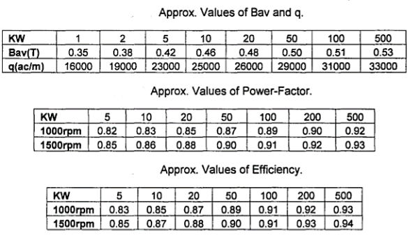
From Table, Values of Bav= 0.4838 T and q = 26802 ac/m corresponding to 30KW
Assuming No. Of Poles (P) = 6,
Sync Speed (Ns) = 120 x f/P = 120 x 50/6 = 1000 RPM and n = 1000/60 = 16.667 rps
From Tables 2 and 3, Values of pf = 0.8621 and eff = 0.88 corresponding to 30 KW and 1000 RPM KW input to motor = KW/eff= 30/0.88 = 34.0908
For Delta connection, Vph = V = 440 Volts

Assuming Winding factor (Kw) = 0.955, Output Coefft (CO) = 11 x Kw x Bav x q x eff x pfx 10-3
= 11 x 0.955 x 0.4838 x 26802 x 0.88 x 0.8621 x 10-3 = 103.3417
D2L = KW/C0x ns = 30/ [103.3417 x 16.667] = 0.0174

Assuming Ventilating ducts (nvd) = 2, each of length (bvd) = 10 mm,
Gross iron Length (Ls) = L - nvd x bvd = 160 - 2 x 10 = 140 mm
Assuming Iron factor (ki) = 0.92, Net Iron length (Li) = Ls x ki = 140 x 0.92 = 128.8 mm

= 329.9 mm 


Computer Program in “C" in MATLAB
% 3ph, KW = 30;V = 440; P = 6; f = 50Sq.Cage 1M
%------------Standard Curves/Tables for%Data-------------->
SKW=[125 10 20 50 100 500J;
SBav=[0.35 0.38 0.42 0.46 0.48 0.50 0.51 0.53];
Sq=[16e3 1ge3 23e3 25e3 26e3 2ge3 31e3 33e3];
SKWa=[5 10 20 50 100 200 500J;
SPF6P=[0.82 0.83 0.85 0.87 0.89 0.9 0.92]; %for 1000RPM
SEFF6P=[0.83 0.85 0.87 0.89 0.91 0.92 0.93];% for 1000R2M
SPF4P=[0.85 0.86 0.88 0.9 0.91 .92 .93J;% for 1500RPM
SEFF4P=[.85 .87 .88 .9 .91 .93 .94J;% for 1500RPM
% (l)<-----------Main Dimensions----------------------->
KW=30;V=440if=50i P=6; %Input Data------>
InsW=3.4;Hw=4;HL=1;insH=6;nvd=2;bvd=0.01;ki=O.92;Bc=1.35;Vph=V;
%Assumptions
Zr=1;kwr=1;cdb=6;Tb=6;cde=6;dd=0.05;Brc=1.35; %Assumptions
Spp=3;Tstrip=1.9;Zsw=3; % Assumption
Kw=0.955;nvd=2;bvd=10;ki=0.92;Tstrip=1.9;insS=0.5;%Assumptions insW=3.4;Hw=4;HL=1;insH=6;nvd=2;ki=0.92;Bc=1.35;%Assumptions
Bav=interp1(SKW,SBav,KW, 'spline');
q=interpl(SKW,Sq,KW, 'spline');
Pf=interp1(SKWa,SPF6P,KW, 'spline');
Eff=interp1(SKWa,SEFF6P,KW, 'spline');
If P=4 pf=interp1(SKWa,SPF4P,KW, 'spline') ;end;
If P=4 eff=interp1(SKWa,SEFF4P,KW, 'spline');end;
KWinp=KW/eff; Iph=KWinp*le3/(3*Vph*pf); Ns=120*f/P;
Ns=Ns/60; CO=11*Kw*Bav*q*eff*pf*le-3; DsqL=l/CO*(KW/ns);
L1=sqrt(DsqL/(0.135*P)A2); L=floor(L1*100) *10; Ls=(L-nvd*bvd);
Li=ki*Ls; D1=sqrt(DsqL/(L/1000)); D=ceil(D1*100)*10;
PP=pi*D/P; LbyPP=L/PP; if LbyPP 2 continue; end;
v=pi*D*ns/1000; if v >30 continue; end;
FI=pi*D/P*L*Bav/1e6;
Design of Stator Winding
Assuming Slots/pole/ph(spp) = 3, No ofslots(S) = spp x 3 x P = 3 x 3 x 6 = 54


Conductors/ph (Zph) = Tph x 2 = 154.8 x 2 = 309.7 Slots/ph (sph) = 54/3 = 18 Conductors/slot (Zs) = Zph/sph = 309.7/18 = 17.2=18(Rounded off to even integer)
Corrected Turns/ph (Tph) = Zs x sph/2 = 18 x 18/2 = 162
Corrected flux (FI) = Vph/4.44x f Tph x Kw = 440/4.44 x 50x162x0.955 = 0.01281 Wb

From above table
Current Density (CDSW) = 3.5 A/mm2
Corresponding to D = 330 mm
Area of CS of conductor (As) = Iph/CDSW = 29.958/3.5 = 8.56 mm2
Assuming Thickness of strip/conductor (Tstrip) = 1.9 mm,
Height of the strip (Hstrip) = As/Tstrip = 5/1.9 = 2.632
Corrected Area of strip/conductor (As) = 0.967 x Hstrip x Tstrip = 0.967 x 5 x 1.9 = 9.1865 mm2
Assuming width-wise Insulation (insW) = 3.4 mm, Strip Insulation Thickness (insS) = 0.5 mm and width-wise No. Of conductors (Zsw) = 3, Slot width (Ws) = [Zsw x (Tstrip + insS) + insW] = (3 x (1.9 + 0.5) + 3.4) = 10.6 mm No of strips/conductors height-wise in a slot (Zsh) = Zs/Zsw = 18/3 = 6 Assuming height of Lip (HL) = Imm, height of Wedge (Hw) = 4 mm, Slot Height (Hs) = [Zsh x (Hstrip + insS) + Hw + HL + insH] = [6 x (5 + 0.5) + 4 + 1 + 6 + 2] = 46 mm
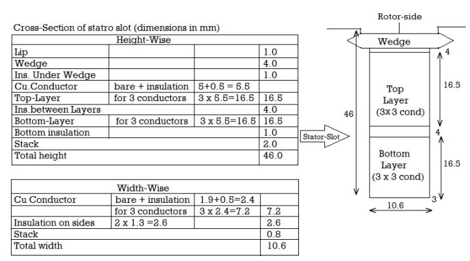
Dia at 1/3 ht from tooth tip (DI3) = D + 2/3 x Hs = 330 + 2/3 x 46 = 360.67 mm
Slot pitch at dia Dl3 (spI3) =  x Dl3 =
  x 360.67/54 = 20.9827mm
Tooth width at dia D13 (Wtl3) = spl3 - Ws = 20.983 - 10.6 = 10.2837 mm
Flux density at 1/3 ht from tooth tIp(BI3) = FI xPx106/LixWtI3xS =
[0.01281x6x106]/[128.8x10.3827x54]= 1.0644T
Max Flux density of the tooth (Btmax) = 1.5 x Bl3 = 1.5 x 1.0644 = 1.5966 T
Mean Length of tum (Lmt) = [2 x L + (2.3 x PP) + 240]/1000 = [2 x 160 + (2.3 x 172.79) + 240]11000 = 0.9574m
Resistance/ph at 20°C (Rph) = 0.021 x Lmt x Tph/As = 0.021 x 0.9574 x 162/9.1865 = 0.35460
Copper Loss (Pcus) = 3 x Iph2 x Rph = 3 x 29.9582 x 0.3546 = 954.6 W
Weight of Copper (Wcus) = Lmt x Tph x 3 x As x 8.911000 = 0.9574 x 162 x 3 x 9.1865 x 8.911000 = 38.04Kg Flux in core (FIc) = FII2 = 0.0128112 = 0.006405 T;
Assuming Flux density in the core (Bc) = 1.35 T,
Area of core (Ac) = FIc x 106 /Bc = 0.006405 x 10⁶/1.35 = 4744.8 mm2
Height of the Core (Hc) = Ac/Li = 4744.8/128.8 = 36.84 mm
Core Outer Dia (DO) = D + 2 x (Hs + Hc) = 330 + 2 x (46 + 36.84) = 495.7 =500 mm (Rounded oft) Corrected ht of core (Hc) = (D0 - D)/2 - Hs = (500 - 330)/2 - 46 = 39 mm
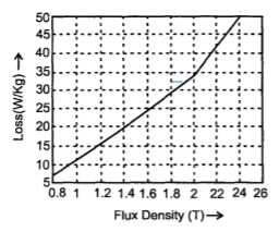
Iron loss in tooth (PitpKg) = 23.92 corresponding to Btmax = 1.5 966T from Fig.
Iron loss in Core (PicpKg) = 18.3 25 corresponding to Bcmax = 1.3 5 T from Fig.
Wt of tooth (Wt) = Li x Wt13 x S x Hs x 7.8 x 10-6
= 128.8 x 10.383 x 54 x 46 x 7.8 x 10-6= 25.91 Kg
Mean dia of the core (Dmcs) = D + (2 x Hs) + Hc = 330 + (2 x 46) + 39 = 461mm
Weight of core (Wc) = Ac x 1t x Dmcs x 7.8 x 10-6 = 4744.8 x 1t x 461 x 7.8 x 10-6 = 53.56 Kg
Iron Loss in Tooth (Pit) = PitpKg x Wt = 23.92 x 25.91 = 619.9 W
Iron Loss in Core (Pic) = PicpKg x Wc = 18.325 x 53.56 = 982.2 W
Design of Squirrel Cage Rotor
Air-gap length (Lg) = 0.2 + 2 x  D xL /106 = 0.66mm
Rotor dia (Dr) = D - 2 x Lg = 330 - 2 x 0.66 = 328.68 mm No. Of Rotor Slots (Sr) should not be equal to the following: (Ss-3 x P) = (54 - 3 x 6) = 36, (Ss - P) = (54 -'- 6) = 48, (Ss - 2 x P) = (54 - 2 x 6) = 42, (Ss - 5 x P) = (54 - 5 x 6) = 24, (Ss - 1) = (54 - 1) = 53, (Ss - 2) = (54 - 2) = 52, (Ss -7) = (54 -7) = 47, (Ss - 8) = (54 - 8) = 46, Hence Sr = 45 Selected
(Note: A new symbol Ss = S = Stator slots and kws = Kw = Stator winding factor is used.)
Slot pItch (sp2) =πxDr/Sr = π x 328.68/45 = 22.946mm
Equivalent Rotor current (Ir) = 0.85 x Iph = 0.85 x 29.958 = 25.464 A
Assuming Winding,factor for Rotor (kwr) = 1 and Conductors/Slot (Zr) = 1,
Bar Current (Ib) = Ir x kws x Ss x Zs/ kwr x Sr x Zr = 25.464 x 0.955 x 54 x 18/1 x 45 x 1 = 525.28 A Assuming Current density in bar (cdb) = 6 A/mm2 and
Thickness of bar (Tb) = 6 mm
Area of cs of bar (Ab) = Ib/cdb = 525.28/6 = 87.55 m2,
Width of bar (Wb) = Ab = 87.55 = 14.59=15 mm (Rounded off) Tb 6 Corrected Area ofcs of bar (Ab) = Wb x Tb x 0.98 = 15 x 6 x 0.98 = 88.2 mm 2 (Factor 0.98 is taken for edges rounding off)
Width of slot (Wsr) = Tb + 0.5 = 6 + 0.5 = 6.5 mm and Ht of slot (Hsr) = Wb + 0.5 = 15 + 0.5 = 15.5 mm Length of bar (Lb) = L + 50 = 160 + 50 = 210 mm
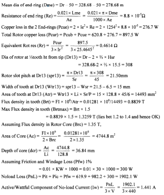
Resistance ofbar(Rb) = 0.021 x Lb/le3/Ab=0.021xLb/ Ab x 1000 = 0.021x210/87.55 x 1000 =5x 10⁻⁵g Copper loss in the bars (Pcub) = Ib2 x Rb x Sr= 525.282 x 5 x 10-5 x 45 = 620.8 W.
End Ring Current (Ie) = Ib x Sr /πxP =525.28 x 45/πx6= 1254 A
Assuming Current density in end ring (cde) = 6 A/mm2.
Area of cs of end ring (Ae) = Ie /cde=1254/2 = 209 mm2,

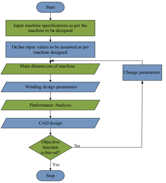
The design of motor in general is a complex procedure and hence requires an easy and understandable design method and tool for the designer. CAD designer for this work looks into the design of DC machines, IM, Synchronous machine, transformers etc. The IM is divided into the design of three phase and single-phase IM with each having its own GUI.
The analysis and synthesis way of designing electrical machines have been used in the design of the machines. The synthesis method is used for DC machine, AC machine, and transformers. The analysis method has been used for the design of switched reluctance method. There is a general toolbox interface that introduces the user to the design of each electrical machine. This is as shown in the figure below.
This introductory GUI makes use of radio buttons that links the designer to the various machine design GUI pages. The machine specifications for each machine design GUI include the following:
The ratings of the machine such as the voltage, KVA, peak current, speed, number of poles.
For some of the motor design, the required outer surface parameters of the machine are required such as the total diameter and length of the machine.
For SRM, stator and rotor pole arc, length of air gap required and active or passive element of the linear SRM. Number of phases for the machine.

Machine Design
Figure above is a generalised design procedure for electrical machines. The analysis on how to design reluctance machine is has been extensively done. The design of the other electrical machines has been done. The design procedure looks into the design of the main dimensions, field windings, No load calculations, performance characteristics and others. For all machines the main criteria for the design are getting the output coefficient. The output coefficient is gotten as
Co = P/D2 x Lx N
Where P is the output of the machine in KVA, D is the diameter of armature (m) and L is the gross length of armature (m), and N is the speed of the machine in RPM. Other relevant considerations are that of the magnetic and electric loadings and are specified as follows.
Pɸ = Bav πD L (Wb)
Where Bav = specific magnetic loading (Wb/m2), D is diameter of the armature (m) and L is the length of the armature (m) and P is the number of poles. The specific magnetic loading,
Bav = Pɸ/ πD L
Total electric loading;
Iz, Z = [ac/ πD], A
Where Iz .Z is the total electric loading, ac is the specific electric loading in A/m. The specific electric loading,
ac = Iz, Z/ πD
The design GUI for the induction motor has been divided into single phase and three phase GUI.
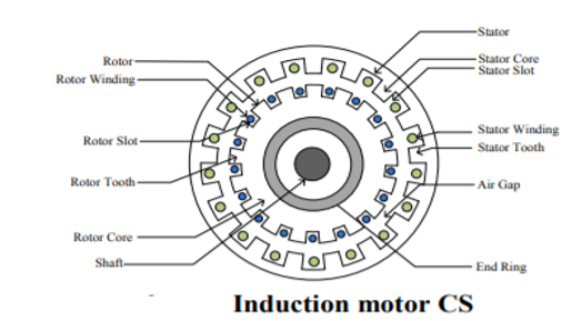
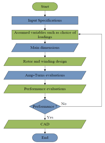
Fig 13. IM Design flowchart
The slip of induction motor matters a lot as it greatly affects the torque of the motor. The slip is the difference between the synchronous speed and the actual speed. The need for slip is because an induction motor does not generate voltage when the rotor is running at a synchronous speed to that of the magnetic field. This is the reason why a much difference in the slip, yields a large torque value. The graph as seen from the GUI shows that with increase in the slip of the machine, the torque is greatly increased until it gets to a value where the slow speed in movement of the rotor is not strong enough to cut across the magnetic field thereby resulting in a reduction in the torque produced.
References:
- K.L. Narang, A Text Book of Electrical Engineering Drawings, Reprint Edition: 1993 / 94 – Satya Prakashan, New Delhi.
- A Shanmugasundaram, G. Gangadharan, R. Palani, - Electrical Machine Design Data Book, 3rd Edition, 3rd Reprint 1988 - Wiely Eastern Ltd., - New Delhi
- Vishnu Murti, “Computer Aided Design for Electrical Machines”, B.S. Publications.
- Bharat Heavy Electricals Limited, Transformers - TMH.