MICRO
Unit - 1Transmission Lines and Waveguides 1.1 Introduction to Microwaves engineering: History of MicrowavesToday, microwaves have become one of the most significant parts of our modern lives. The presence of microwaves is more or less felt in every important activity of human existence. Through satellites, microwaves are used extensively in transmitting TV programmes, voice, data, facsimile signals, cellular phones messages, SOS messages, weather forecasts, GPS signals, photo signals, air to air communication, ground to air communication, ground to ground communication, navigational signals, etc.Most of radars use microwaves to control the commercial aeroplanes, ships, fighter aircrafts, missiles, tanks, etc. Besides these applications, microwaves are also used for many commercial applications such as cooking, drying, physical diathermy, treating cancer patients, etc. With the advancement of technology, the use of electromagnetic spectrum, particularly in radio and microwave region, has increased manifold and the spectrum has become a scarce resource. The advent of digital services is going to play a significant role in managing the spectrum in the most efficient manner. Each part of the electromagnetic spectrum has its unique feature and peculiarity which need to be handled in professional manner to ensure the optimum utilisation of the entire spectrum. The ever increasing demands of microwave devices, systems and subsystems for commercial and military applications are raising the bar with passage of time. Therefore, there is a definite need to understand the basic concepts and the intricacies of microwave engineering to do justice towards effective and efficient utilisation of electromagnetic spectrum.History of Microwaves The electromagnetic theory was formulated sometime in 1873 by James Clerk Maxwell. Maxwell translated Faraday’s experiments into mathematical notations. He developed Maxwell field equations for laws of light, electricity and magnetism. During the period of 1885 to 1887, Oliver Heaviside worked on Maxwell’s mathematical notations and structured them in proper equation forms. Thereafter, a series of experiments were carried out by Heinrich Hertz, a German professor of physics from 1887 to 1894, who confirmed the complete validity of Maxwell’s theory of electromagnetic waves. In 1920, George C Southworth experimented with high frequency signals and measured theirwavelengths. While working for AT&T, he carried out experimentation for the first time on transmission and reception of telegraph signals using 20 feet long pipes having diameter of 4 –5 inch. In 1922, Albert H Taylor and Leo C Young identified the possibility of radio detection and ranging of enemy ships through radars. During the period of 1922 to 1937, Guglielmo Marconi explored the possibilities of using electromagnetic waves as a means of wireless communications. He developed parabolic antennas in higher frequencies and reached up to the frequency range of 550 MHz. It was only in the 1940’s (World War II), the microwave theory received the due impetus that led to radar development. After World War II, many researchers started working on various types of radars especially for military applications. Soon after the birth of radar, the microwave communications drew the attention of researchers and thus began the development. 1.2 Microwave Frequency Bands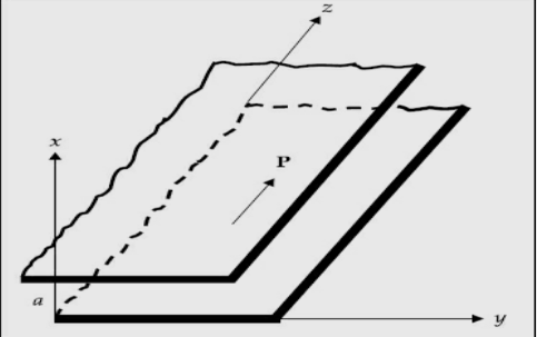
 In these structures, the waves are no more uniform plane waves. Hence their propagation characteristics are described in terms of Transverse Electric (TE) and Transverse Magnetic (TM) waves. Let us assume that,a. the plates are extended to infinity in y and z-direction.b. the plates are perfectly conducting c. the plates are separated by a distance of ‘a’ metres in the x- directiond. the space between the plates is air or free space e. the direction of power flow is z f. all field components in z-direction vary as
 Here γp is the propagation constant, αp is the attenuation constant and βp is the phase constant. In time varying form the fields vary as,
 g. the field is uniform in y-direction as the plates are extended to infinity in y-directionAs the medium between the plates is air, the first and second Maxwell’s equations are given by ∇ × H = j ω∈0E (1)and ∇ × E = −j μ0H (2) The corresponding wave equations in air are: ∇2E = −ω2 μ0 ∈0 E (3) and ∇2 H = −ω2 μ0 ∈0 H (4)
 Expanding Equation (1), we get,
  =
=  Equating the respective components on either side, weget,
 =
= ------5
  =
=
 =
= 5
5
 Similarly, expanding Equation (2) and equating the respective components on both sides, we get,

 (6)If H = H0, at z = 0, the field components can be written as,
 and similarly,
 (7)
(7)

 and substituting Equation (7) in Equations (5) and (6), we get,


 (8)But all terms containing derivatives with respect to y vanish as the fields do not vary with y. Hence Equation (8) becomes,
 (9)
(9)


 As E can be written as,

 (10)
(10)
 and similarly, The wave equations
 and
and and become
 or,
or,
 (11) Solving Equation (9) simultaneously, we get the field components as,

 (12)
(12)

where, (13)It is seen from Equation (12) that if Ez = 0, Hz = 0 as in the case of uniform plane wave, all the components will vanish. Therefore, there should be either E or H in the direction of propagation. In view of this, the solution is divided into two parts,1.Transverse Electric waves (TE waves) In this Ez = 0 and Hz ≠ 0. 2.Transverse Magnetic waves (TM waves) In this Hz = 0 and Ez ≠ 0. FIELD COMPONENTS FOR TE WAVES (Ez= 0)TE wave means transverse electric wave for which there is no component of E in the direction of propagation, or, Ez = 0. For this case, as Ez = 0, it is obvious from Equation (12) that Hy= 0 and Ex = 0. Substituting these values in Equation (11), we get the component of y as,
 that is,
  or,
or, (14) or,
  (15) where,
 This equation has the solution in the form of
  (16) where A1 and A2 are constants. Using the boundary condition, Ey = 0 at x = 0, A2 is zero. Therefore,
 (17)At x = a, Ey = 0 requires that
 (18)Here if m = 0, all the field components vanish.Therefore,
 (19) Substituting Equation (19) in Equation (18), the other components are obtained. The resultant expressions for the field components are:

 These represent the fields for TEm. The field components in complete form are:

 The instantaneous electric and magnetic fields for TE1 wave at some instant of time are shown,
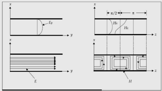 ( Electric and Magnetic Fields between parallel platesfor TE1 wave) TE waves are represented in the form of TEm where m represents variation along x. FIELD COMPONENTS OF TM WAVES (Hz = 0)TM wave means transverse magnetic wave for which there is no component of magnetic field in the direction of propagation, or, Hz = 0. The wave equation for y-component of H from Equation (11) can be written
 (20)or,
  (21)where,
 The solution of Equation (21) appears in the form of
 (22)As the tangential component of H is not zero at the surface of a conductor, the boundary condition cannot be applied directly to Hy to obtain A3 and A4. From Equation (9) we have
 (23) Putting Equation (22) in Equation (23), and writing the equation for Ez, we get,
 (24)The boundary conditions are:
 Applying the first boundary condition, A3 becomes zero. For the second boundary condition, Ez = 0 at x = a.Ez becomes zero if
 Here, m= 0 is also possible as there still exist some more components.
 (25) From Equations (9) and (25) we get the remaining components Hy and Ex. As a whole, the expressions of field components for TM waves are:
 (26)
(26)  (27)The field components in complete form for TMm waves are:

 The field variations for TM1 wave between parallel plates are shown below,
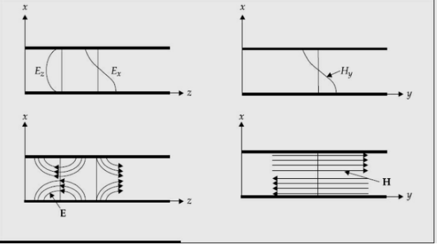
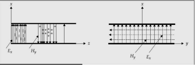
 TRANSVERSE ELECTROMAGNETIC WAVE (TEM WAVE)TEM wave is a wave for which there are no components of E and H in the direction of propagation. TEM wave is a TMm wave for m = 0, or, TEM = TEM0. TEM wave is called principal wave.The field components of TEM wave are obtained from m = 0. They are:
 The propagation parameters for TEM wave are


 TEM wave between parallel plates are given below,
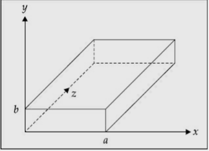
 Rectangular Waveguide : A rectangular waveguide is a hollow metallic device with four sides closed and two sides open. It can be used as a radiator a high pass filter a transmission line a feed element to antennasA hollow rectangular waveguide supports only TE and TM waves/modes and it does not support TEM mode.DERIVATION OF FIELD EQUATIONS IN RECTANGULAR HOLLOW WAVEGUIDES Field expressions can be obtained from the solutions of Maxwell’s equations and wave equations. Assumptions:Space inside the waveguide is free space or air. The walls of the waveguides are perfectly conducting. The direction of propagation of power is z. The dimension of the narrow wall is b metres. The dimension of the broad wall is a metres.The fields in z-direction vary as
 As the medium inside the waveguide is air, the first and second Maxwell’s equations are given by ∇ × H = jω∈ E ∇ × E = jωμ H
 Expanding these equations, we get,
  =
= +
+ =
=
 Equating the respective components, we get

 and
and


 (29) As the fields are assumed to be varying in the form of
 , combining time variation, we get,

 Similarly,


and,
 Substituting Equation (30) in Equations (28) and (29), we get,
  =
= =
=
 -
- =
=
 (31)
(31)


 The wave equations are: ∇2E = −ω2μ ∈ E ∇2H = −ω2μ ∈ H These can be written as,
 +
+ +
+ =
=
 +
+ +
+ =
=
 The wave equations for Ez and Hz are given by,
 (32) Equation (31) can be mathematically manipulated to get the following. Consider,
 = -
= - (33)and,
 (34) Equation (33) becomes,
 -
- (35) But Ey from Equation (34) is,
 (36) From Equations (35) and (36), we get,
 or,
or, =
= or,
or,
 where,
  Similarly,

 (37) In the above equations, if Ez= 0 and Hz= 0, all the field components vanish. Hence, the wave cannot satisfy TEM wave characteristics. They are transverse magnetic (TM) and transverse electric (TE) waves. A typical rectangular waveguide is shown,
 Transverse Magnetic (TM) Waves in Rectangular WaveguideTM waves are EM waves for which there is no component of H in the direction of propagation, that is, Hz= 0. The wave equations given by Equation (32) can be easily solved using the method of product solution. In this method, two ordinary differential equations with known solutions areobtained.We know that,
  If,
If, (38) where X is only a function of x and Y is only a function of y. From Equations (32) and (33), we can write,
 or,
or,


 (39)This expression equates a function of x to another function of y. This is possible when each of these functions is equal to some constant. Let the constant be B
 (40)and,
 (41) The general solution of these equations are X = A1cos Cx + A2sin Cx, where
 and Y = A3cos By + A4sin By
 = A1A3cosCx cos By + A1A4cos Cx sin By + A2A3sin Cx cosBy + A2A4sin Cx sin ByThe constants A1, A2, A3, A4 are evaluated using the boundary conditions. Using the boundary condition
 at x=0
 This is zero if A1= 0
 (42)At y = 0, Equation (42) becomes,
 For this to vanish, A2 or A3can be zero, while assuming C ≠ 0. Keeping A2 = 0 in Equation (42),
 becomes zero.Hence instead of A2 = 0 assume A3 = 0. Then Equation (42) becomes,
 sin Cx sin By=K sinCx sin By[K = A2A4]At x = a,
 K sin Ca sin ByFor this to vanish for all values of y (assuming B ≠ 0) the constant C must beC=
 At y = b,
 For this to vanish for all values of x, B must be
 B=
B= Hence, the final expression for is
 y=K sin Cx sin By (43) From Equations (42) and (43), we get
 (44)
(44)

 where
where Therefore, the field components for a TM wave are: TMmnwavefield components


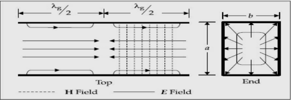
 Field variations of TM11 mode/wave are shown,
 Transverse Electric WavesTE waves are EM waves for which there is no component of E in the direction of propagation, that is, Ez= 0. The expressions for TE waves are derived in the same manner as in the case of TM waves. From Equation (37), we have,
 But Ez= 0, hence,
 The first boundary condition is Ex = 0 at y = 0,i.e.
  but,
but, 

As, The secondary boundary condition is Ex = 0 at y = b, A is
  Bshould be
  Moreover,
  and,
and,  c=
c=
 Substituting Equation (45) in Equation (37), we get


 The field expressions for TE waves in complete form are


 where,

 As TE10 is popular, its field equations are,


 The field patterns are shown below,
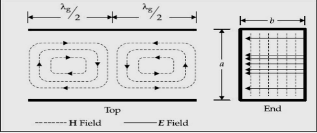 Field pattern of
  mode 1.7 Wave Guide Parameters1.Cut-off wavelength (λc):Cut-off wavelength is the wavelength of signal below which the propagation of the wave occurs and above which there is attenuation or no propagation. The cut-off wavelength is denoted by 'λc'. The cut-off wavelength for rectangular waveguide for both TEmn and TMmn is given by,
  where, a = Wide dimension of waveguide, b = Narrow dimension of waveguide. Therefore, the operating frequency must be above the cut-off frequency in order to propagate the wave in waveguide.The frequency associated with cut-off wavelength is called cut-off frequency and denoted as 'fc', and is given by,
  This is the cut-off frequency for both TEmn and TMmn mode. where, µ = Permeability of free space ε = Permittivity of free space. 2. Dominant Mode:It is the mode for both TE and TM which offers highest cut-off wavelength (λ0) or lowest cut-off frequency (f0) in a particular waveguide. For TEmn mode, TE10 is the dominant mode and for TMmn mode, TM11 is the dominant mode. As mentioned earlier, dominant mode is almost a low loss, distortionless transmission while higher modes contains losses and harmonic distortion. For practical, electromagnetic transmission TE10 and TM11modes are used. 3. Guide Wavelength (λg): It is defined as the distance travelled by the wave in order to undergo a phase shift of 2π radians.It is related to the phase constant by relation,
  The wavelength in the waveguide is different from the wavelength in free space. In fact, it is related to free space wavelength λ0 and cut-off wavelength λc by,
 This equation is valid for any waveguide mode. 4. Group velocity (Vg): If there is modulation in the carrier, the modulation envelope actually travels at a velocity slower than that of the carrier and slower than the speed of light. The velocity of modulation envelope is called the group velocity 'Vg'. This happens when modulated signal travels in a waveguide, the modulation goes on slipping backward with respect to the carrier. Group velocity 'Vg' is defined as the rate at which the wave propagates through the waveguide and is given by, Vg= dω/dβ.In an air filled or hollow waveguide, Vg = ( λ0 / λg) · c Putting value of λg,
  where, c = Velocity of light fc = Cut-off frequency f = c/λ 5. Phase Velocity (Vp): Phase velocity (Vp) is defined as the rate at which the wave changes its phase, in terms of guide wavelength. i.e.
  or, =λg .f =
 =
= =
= =
= where,
  and,
and,  For a wave travelling through the waveguide, the speed with which a particular phase of the wave travels in the propagation direction is defined as phase velocity (Vp). ,
 6. Wave Impedance: Wave impedance is defined as the ratio of transverse electric field to the transverse magnetic field at any point in the waveguide. Wave impedance is also known as a characteristic impedance.
 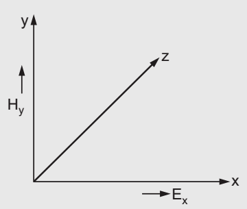 From the above figure, wave impedance is given by,Zg=Ex/Hy= -EY/HXWave impedance, for TM wave in rectangular waveguide,is given by,
 Wave impedance for TE wave in rectangular waveguide, is given by, where,
 Intrinsic impedance for free space for air
  =
= 1.8 Introduction to Co-axial LineTransmission lines based on two conductor transmission theory are “coaxial lines” as shown in the figure below,
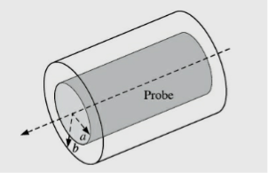 A coaxial line is a two conductor transmission line in which both the conductors have the same axis and the centre conductor is a solid conductor placed inline of the axis of a hollow metallic cylinder known as outer conductor. This type of arrangement supports the TEM mode of wave propagation. The coaxial lines are widely used due to zero cut-off frequency and broad low attenuation bandwidth. Some of the commercially available low loss coaxial cables have lossless than 0.4 dB/m over DC-18 GHz frequency range. 1.9 Rectangular Waveguide Cavity ResonatorsBasically resonators are used for storing energy. At very high frequencies, the RLC circuit elements are inefficient when used as resonators because the circuit dimensions are comparable with the operating wavelength. Due to this, unwanted radiation takes place. Hence at high frequencies, the RLC resonant circuits are replaced by electromagnetic resonant cavities. When a perfectly conducting plane is used to close the wave guide, along the axis of propagation, a standing wave pattern is produced. At the end walls, the tangential component of the electric field intensity is zero. The electric field intensity will be zero at a half wavelength back along the guide. As the electric field is zero at any half wave point, we can introduce a conducting plane at every such points without changing field configurations. Thus in between the two conducting planes, an exciting antenna can be realized then. Thus in between two planes we can have a cavity produced which shows properties of parallel resonant circuit. Hence when one end of the waveguide is terminated in short circuit, the reflections of the waves takes place, which results in the generation of standing waves. Consider a section of a rectangular waveguide with both the ends terminated by a shorting plate. When the short plate is inserted at a distance equal to the multiplies of λg/2, a cavity is produced.
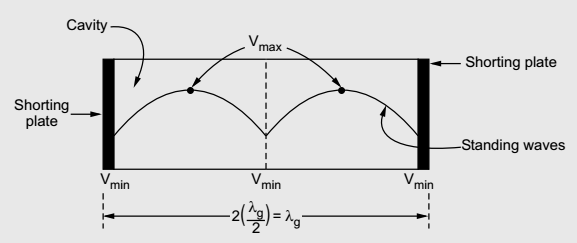 The waveguide section from which the cavity resonator is constructed may be either rectangular or circular. So depending upon the type of waveguide, we can have rectangular cavity and circular cavity resonator.
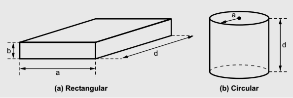
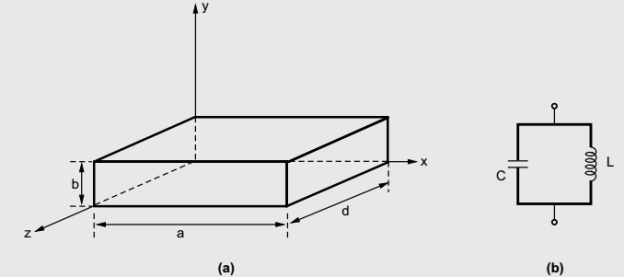
 The cavity resonators are used as tuned circuits. The cavity resonators are also used in UMF tubes, klystron amplifier, oscillators, duplexes of radar. The circular cavity resonators are also used in microwave frequency meter. In general the rectangular waveguides are constructed from closed sections of the waveguide, as the waveguide is the type of the transmission line. Usually the rectangular waveguide resonators are short circuited at both the ends to avoid the radiation losses from open end of the waveguide. Due to short circuited ends of thewaveguide, a cavity or closed box is formed. Within this cavity, both the energies, electric and magnetic are stored. The power dissipation is observed at the metallic, conducting walls of the waveguides as well as in the dielectric inside the cavity. Through a small aperture or a small probe or a loop such resonators are coupled. The geometry of the rectangular cavity resonator is as shown in the figure below,
 The guide wavelength is given by,
 (1) The most dominant mode in the rectangular waveguide is TE10 mode. Basically for the dominant mode, the resonant frequency of the field configuration is lowest. For TE10mode, λc= 2a. Hence guide wavelength is given by,
  From equation (2) it is clear that, dimension 'a' is fixed for the resonator. So also the guide wavelength λg is fixed. But in general the frequency is given by,
 (3)As λ0 is fixed and c is velocity of light which is also constant, for the given mode, the frequency has fixed value denoted by f0. Thus the rectangular resonant cavity supports only one frequency for a given mode. This frequency is called resonant frequency and thus the cavity formed is called resonant cavity. This cavity resonator behaves similar to parallel LC resonant circuit commonly called tank circuits. The resonant frequency for such equivalent parallel circuit is given by,
 Expression for Resonant Frequency(f0) for Rectangular Cavity Resonator For the rectangular waveguide we have a relation given by,
  therefore,
 (4)But for a condition of a wave propagation, we can write,
 Hence equation (4) can be written as,
 (5)But the condition for the cavity resonator is that the cavity must be an integer multiple of a half-guide wavelength long at the resonant frequency. Hence we can write,
  (6)Here p is known as number of half wavelength variations of either electric or magnetic fields along z-direction. Thus depending on the value of p, the general wave mode through the cavity resonators are denoted by TEmnp for the transverse electric (TE) wave and TMmnp for the transverse magnetic (TM) wave. To have a resonator resonating at a fixed frequency, ω0, or f0,substituting value of β̅ from equation (6) in equation (5), we can write,
 or,
or, But ω0 = 2πf0,
 (7)We can modify this expression by taking π2 out of the radical term as π, and write,
  (8) If the resonator cavity is filled with a air, then we can write,
  where c = 3 x 10⁸ m/s = Velocity of light Thus for free space within the cavity, the frequency of resonance is given by,
  (9)Equations (8) and (9) indicate the resonant frequency of a rectangular cavity resonator with dimensions a, b and d for both TMmnp and TEmnp modes in it. 1.10 Circular Waveguide Cavity ResonatorsCircular cavity resonator can be constructed from a circular waveguide cutting into a section and shorting both the ends of it. The circular cavity resonators are mainly used in microwave frequency meters. The mechanical tuning of the resonant frequency is done with the help of movable top wall. The cavity is coupled to a waveguide through a small aperture. The dominant mode in circular waveguide is TE11 mode. The dominant mode in case of the circular cavity resonator is given by TE11. In general, the circular cavity resonator modes are specified as TMnmp for the transverse magnetic (TM) wave and TEnmp for the transverse electric (TE) wave. Let us consider a circular cavity resonator constructed from the circular waveguide with uniform circular cross-section with radius ‘a’. The geometry of the circular cavity resonator is as shown below,
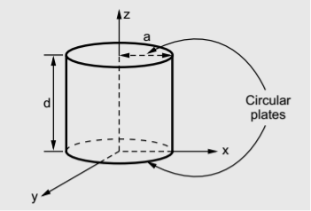 Both the ends of the section of circular cavity resonator of length 'd' are shorted with the help of circular shorting plates. Expression for Resonant Frequency (f0) of the Circular Cavity Resonator For a circular waveguide, we have,
 (1)Where pnm is the eigenvalue and ‘a’ is the radius of the circular cylinder. But for the wave propagation, the condition can be written as,
 (2)substituting value ofγ̅ in equation (1), we get,
 or,
or,  (3)But the condition for the circular cavity resonator remains the same as the condition in the rectangular cavity resonator which is given by,
  (4)Depending upon the value of p, the general modes through the circular cavity resonator are denoted by TEnmp and TMnmp. With this value of β̅substituted in the expression for ω, the cavity resonator supports only one frequency ω0 or f0.Therefore,
 (5)For TMnmp wave:
  (6)For a free space, as a dielectric within the circular cavity, we can write,
 where c = Velocity of light = 3x10⁸ m/s Hence for a free space, the expression for the resonant frequency of circular cavityresonator can be modified as,
 (7)Expression for the resonant frequency given by equations (6), (7) is for TMnmp mode. For the TEnmp mode, the expressions for f0 are given as follows. For TEnmp wave:
  (8)For free space within the circular cavity, the expressions for the resonant frequency for TEnmp mode is given by,
 (9)
(9)
Reference Books1. M. Kulkarni, “Microwave and Radar engineering”, 3rd edition, Umesh Publications.2. ML Sisodia& GS Raghuvamshi, “Microwave Circuits and Passive Devices”Wiley, 1987.3. M L Sisodia& G S Raghuvanshi, “Basic Microwave Techniques and Laboratory Manual”, New Age International (P) Limited, Publishers.
Frequency range
Designation (Old)
Designation (New) as per NATO
500 MHz-1GHz
VHF
C (A and B from 0-500 MHz)
1-2 GHz
L
D
2-3 GHz
S
E
3-4 GHz
S
F
4-6 GHz
C
G
6-8 GHz
C
H
8-10 GHz
X
I
10-12.4 GHz
X
J
12.4-18 GHz
Ku
J
18-20 GHz
K
J
20-26.5 GHz
K
K
26.5-40 GHz
Ka
K
40-300 GHz
Millimeter
L(40-60 GHz)
M(60-100 GHz)
.>300 GHz
Sub millimeter
1.3 Applications of MicrowaveThe unique characteristics of microwaves make this band very popular choice for use in numerous civil and military applications. Microwaves band has numerous applications for military, civil and scientific applications. (a)Military applications of radar: After World War II, microwave engineering hogged the lime light and became almost synonymous with RADAR (Radio Detection and Ranging). Radar is used for detecting, locating, acquiring and tracking any flying object with reasonable cross sectional area. Today, most of the modern radars are operating in microwave region. Without radar, no military operation is going to be successful. It is widely used in army, navy and air force for different purposes. There are varieties of military radars operating in different bands of microwave spectrum which are used for early warning, day and night air and battlefield surveillance, target acquisitions, target tracking and weapon controls. Early warning and surveillance radars generally operate in L and S band whereas tracking and fire control radars work in X band. These radars can operatefrom the ground, ship born and airborne platforms. Most commonly deployed radars for military operations are of the following types. Early warning and surveillance radars High resolution radar used in direction finding of enemy troops, tanks, planes and ships Missile tracking radars Fire control radars Reconnaissance radars Weather detecting radars Missile guidance radars Air traffic control radars exclusively used for military operations Dedicated microwave (LOS) and satellite communication.(b) Civilian applications of radar: Besides military applications, there are a number of areas in which radars are used for commercial and civil applications. In the commercial sectors radars are deployed for air traffic control of commercial aeroplanes, aircraft landing systems, direction findings, policing, motion detectors (impulse generator for opening industrial gates/doors, security alarms, etc.), vehicle collision avoidance, distance measurement, airport surveillance, marine navigation, radio astronomy, terrestrial and satellite communication links. Radar is also used in policing to locate speeding vehicles and control street traffic. In sports, radars are used to detect the speed of tennis balls.(c) Scientific applications of radar: Radars are used for many scientific applications such as weather forecast, remote sensing of the atmosphere, oceanography applications, medical diagnostics and therapy. Weather forecasters use radar in conjunction with Lidar (optical/laser radar) to study storms and locate hurricanes. To study and map temperature profiles and moisture conditions, microwave radio meters are used by researchers. A number of studies are also being carried out on remote sensing of natural resources through radars. Also scientists use radars to track the migration of birds, to map the distant planets. Balloon-borne radars are used to control drug trafficking. With the help of surface radars, commercial ships are warned about icebergs and nearby vessels. (d) Microwaves in applied research: Microwaves are used by physicists and nuclear scientists to study the behaviour of matter as various molecular and nuclear resonances occur at radio and microwave frequencies. Microwaves are nowadays widely used in different type of spectroscopy in which information is obtained on thestructure and chemical bonding of molecules and crystals by measuring the wavelengths of microwaves emitted or absorbed the sample. (e) Microwave and satellite communication: Microwave communication is a type of transmission of audio, video, data or any other form of signals using a series of microwave towers. This type of communication is a form of “Line of Sight Communication” where all the microwave towers must fall in visual line with each other for better transmission and reproduction of signals at receiving ends. The first message based on microwave communication technology was transmitted in 1945 from microwave towers located in New York and Philadelphia. After the successful transmission of message it became very popular method of data transmission. With the advent of satellite technology “Line of Sight” form of microwave communication is not much in use in telecommunication industry. (f) Medical applications: In medical field too, a number of studies have been carried out and many are underway to explore the optimum use of microwaves. The most important use of microwaves in medical field is the treatment of cancer patients.(g) Industrial applicationsHeating: In last two decades researchers have been able to design many commercial and domestic appliances using principle of microwave heating. The most popular and successful device is microwave oven. Microwave oven is used for cooking and uniform heating of food materials. Microwaves penetrate the food and excite water and fat molecules in a very uniform manner unlike conventional ovens where heating is done by conduction method. The commonly used frequency in microwave oven is in S-band range (2450 MHz). In this frequency range, microwaves are absorbed by water, fats and sugars. When absorbed, they are converted directly into heat. However, microwaves are not absorbed by most plastics, glass and ceramics. 1.4 General Solution for TEMTransmission Lines are two conductor structures which can support a transverse electromagnetic mode of propagation (TEM).The electric and magnetic fields of TEM waves have only transverse components; that is, in the direction of propagation, EZ = HZ = 0. Coaxial cables, parallel plates, and two-wire lines are examples of practical transmission lines. Waveguide is a special form of transmission line. In general, the term waveguide is applied to structures consisting of a single conductor. Unlike the two-conductor structures, the single-conductor structures cannot support a TEM mode. A waveguide is just a hollow metallic tube that may be rectangular or circular in shape and is used to guide the microwaves. Waveguides are constructed of brass, copper, or aluminium. The inner surface of the waveguide is usually coated with either gold or silver. 1.5 TE and TM WavesWaveguides are primarily used at microwave and optical frequency ranges, whereas transmission lines are used at lower frequencies. In practice, the required operating frequency band and the amount of power to be transferred are the main basis for the choosing the structure. The cause forthe inefficiency of Transmission lines is the skin effect and dielectric losses. In waveguides, the electromagnetic (EM) waves are propagated in bounded medium. So, no power is lost due to radiation. Since the guides are generally air filled, the dielectric loss is negligible. However, some power is lost as heat in the walls of the guides owing to the skin effect. This loss in the walls is negligible. The EM waves can be propagated in several modes within a waveguide, namely, in the Transverse Electric (TE) and Transverse Magnetic (TM) modes. The TE wave has the electric field only in the plane that is transverse to the direction of propagation (i.e. the longitudinal components, Ez = 0 and Hz ≠ 0). The TM wave has only the magnetic field in the transverse plane (i.e. in the direction of propagation, Hz = 0, and Ez ≠ 0). These modes are dependent on the solutions of Maxwell’s equation for the given waveguide. Every mode has a particular cut-off frequency, and this cut-off frequency is dependent on physical dimensions of the waveguides. Below the cut-off frequency, the waveguide does not transmit signals. The dominant mode is the mode having the lowest cut-off frequency. 1.6 Parallel Plate Waveguide and Rectangular Waveguide

 =
= 


 and similarly, The wave equations
 and
and and become


where,
 that is,
  or,
or, ( Electric and Magnetic Fields between parallel platesfor TE1 wave) TE waves are represented in the form of TEm where m represents variation along x. FIELD COMPONENTS OF TM WAVES (Hz = 0)TM wave means transverse magnetic wave for which there is no component of magnetic field in the direction of propagation, or, Hz = 0. The wave equation for y-component of H from Equation (11) can be written

 TEM wave between parallel plates are given below,
 =
= and
andand,

 or,
or,
 where,


 or,
or,


 (44)
(44)


 But Ez= 0, hence,
 The first boundary condition is Ex = 0 at y = 0,i.e.
  but,
but, 
As,
 The secondary boundary condition is Ex = 0 at y = b, A is


 The field expressions for TE waves in complete form are


 where,
  Field pattern of
  where, a = Wide dimension of waveguide, b = Narrow dimension of waveguide. Therefore, the operating frequency must be above the cut-off frequency in order to propagate the wave in waveguide.The frequency associated with cut-off wavelength is called cut-off frequency and denoted as 'fc', and is given by,
 This equation is valid for any waveguide mode. 4. Group velocity (Vg): If there is modulation in the carrier, the modulation envelope actually travels at a velocity slower than that of the carrier and slower than the speed of light. The velocity of modulation envelope is called the group velocity 'Vg'. This happens when modulated signal travels in a waveguide, the modulation goes on slipping backward with respect to the carrier. Group velocity 'Vg' is defined as the rate at which the wave propagates through the waveguide and is given by, Vg= dω/dβ.In an air filled or hollow waveguide, Vg = ( λ0 / λg) · c Putting value of λg,
  where, c = Velocity of light fc = Cut-off frequency f = c/λ 5. Phase Velocity (Vp): Phase velocity (Vp) is defined as the rate at which the wave changes its phase, in terms of guide wavelength. i.e.
  6. Wave Impedance: Wave impedance is defined as the ratio of transverse electric field to the transverse magnetic field at any point in the waveguide. Wave impedance is also known as a characteristic impedance.
  From the above figure, wave impedance is given by,Zg=Ex/Hy= -EY/HXWave impedance, for TM wave in rectangular waveguide,is given by,
 A coaxial line is a two conductor transmission line in which both the conductors have the same axis and the centre conductor is a solid conductor placed inline of the axis of a hollow metallic cylinder known as outer conductor. This type of arrangement supports the TEM mode of wave propagation. The coaxial lines are widely used due to zero cut-off frequency and broad low attenuation bandwidth. Some of the commercially available low loss coaxial cables have lossless than 0.4 dB/m over DC-18 GHz frequency range. 1.9 Rectangular Waveguide Cavity ResonatorsBasically resonators are used for storing energy. At very high frequencies, the RLC circuit elements are inefficient when used as resonators because the circuit dimensions are comparable with the operating wavelength. Due to this, unwanted radiation takes place. Hence at high frequencies, the RLC resonant circuits are replaced by electromagnetic resonant cavities. When a perfectly conducting plane is used to close the wave guide, along the axis of propagation, a standing wave pattern is produced. At the end walls, the tangential component of the electric field intensity is zero. The electric field intensity will be zero at a half wavelength back along the guide. As the electric field is zero at any half wave point, we can introduce a conducting plane at every such points without changing field configurations. Thus in between the two conducting planes, an exciting antenna can be realized then. Thus in between two planes we can have a cavity produced which shows properties of parallel resonant circuit. Hence when one end of the waveguide is terminated in short circuit, the reflections of the waves takes place, which results in the generation of standing waves. Consider a section of a rectangular waveguide with both the ends terminated by a shorting plate. When the short plate is inserted at a distance equal to the multiplies of λg/2, a cavity is produced.
 The waveguide section from which the cavity resonator is constructed may be either rectangular or circular. So depending upon the type of waveguide, we can have rectangular cavity and circular cavity resonator.
 The guide wavelength is given by,
 From equation (2) it is clear that, dimension 'a' is fixed for the resonator. So also the guide wavelength λg is fixed. But in general the frequency is given by,
 Both the ends of the section of circular cavity resonator of length 'd' are shorted with the help of circular shorting plates. Expression for Resonant Frequency (f0) of the Circular Cavity Resonator For a circular waveguide, we have,
Reference Books1. M. Kulkarni, “Microwave and Radar engineering”, 3rd edition, Umesh Publications.2. ML Sisodia& GS Raghuvamshi, “Microwave Circuits and Passive Devices”Wiley, 1987.3. M L Sisodia& G S Raghuvanshi, “Basic Microwave Techniques and Laboratory Manual”, New Age International (P) Limited, Publishers.
0 matching results found
Browse by Topics