UNIT 1
Light Wave System Components
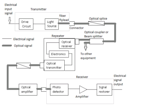
Optical Fiber System
The transmission medium consists of a pair of wires , a co-axial cable or a radio link through free space down in which the signal is transmitted to the receiver, where it is transformed into the original electrical information signal before being passed to the destination.
In any transmission medium, the signal is attenuated or it suffers loss and also subjected to degradations due to contamination by random variables and noise as well as possible distortions imposed by mechanisms within the medium itself.
The information source provides an electrical signal to the transmitter comprising an electrical stage, which drives an optical source to give modulation of the light wave carrier
The optical source provides the electrical-optical conversion, which may be either a semiconductor laser or LED.
The transmission medium consists of an optical fiber cable and the receiver consists of an optical detector, which drives a further electrical stage and hence provides demodulation of the optical carrier.
Photodiodes, Phototransistors and photoconductors are utilized for the detection of optical signal and the optical electrical conversion.
It mainly consists of three elements:
Transmitter:
At the optical transmitter, an electric signal is applied . The optical transmitter consists of a driver circuit, the light source and fiber fly lead.
- Driver circuit is used to drive the light source.
- Light source converts the electrical signal to optical signal.
- Fiber fly lead is used to connect optical signal to optical fiber.
Transmission channel:
It consists of a cable that provides mechanical and environmental protection to the optical fibers contained inside. Each optical fiber acts as an individual channel.
- Optical splice is used to permanently join two individual optical fibers.
- Optical connector is for temporary non-fixed joints between two individual optical fibers.
- Optical coupler or splitter provides signal to other devices.
The Repeater converts the optical signal into electrical signal using optical receiver and passes it to electronic circuit where it is reshaped and amplified as it gets attenuated and distorted with increasing distance because of scattering, absorption and dispersion in waveguides, and this signal is then again converted into optical signal by the optical transmitter.
Receiver:
Optical signal is applied to the optical receiver which consists of photo detector, amplifier and signal restorer.
- Photo detector converts the optical signal to electrical signal.
- Signal restorers and amplifiers are used to improve signal to noise ratio of the signal, because of the presence of noise introduced in the signal due to the use of photo detectors.
- For short distance communication the main elements are required.
Source- LED
Fiber- Multimode step index fiber
Detector- PIN detector
- For long distance communication main elements are there is need for couplers, beam splitters, repeaters, optical amplifiers.
Source- LASER diode
Fiber- single mode fiber
Detector- Avalanche photo diode (APD)
In this communication channel there is no physical contact between the transmitting and the receiving antenna. The transmitted signal spreads in all directions. This results in the attenuation of the signal. In order to avoid the attenuation we use line communication.
In line communication the signal is transmitted from the transmitter to the receiver through the connecting wire. This communication system requires a solid medium as communication channel between the transmitter and the receiver. This medium is called transmission line.
The principle of such communication are
- Two-wire transmission lines
- Coaxial cables
- Optical fiber
Two – wire transmission lines and co-axial cables are used to transmit AF and UHF signals while optical fibers are used to transmit optical signals. At high frequency two-wire transmission lines are affected by electromagnetic interference and radiation.
Optical fiber
Optical fiber is a cable, known as cylindrical dielectric waveguide made of low loss material.
An optical fiber also considers the parameters like the environment in which it is operating, the tensile strength, durability and rigidity.
The Fiber optic cable is made of high quality extruded glass (si) or plastic, and it is flexible.
The diameter of the fiber optic cable is in between 0.25 to 0.5mm which is slightly thicker than a human hair .
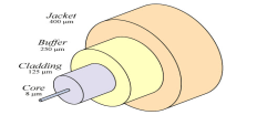 Fiber Optic cable
A Fiber Optic Cable consists of four parts.
- Core
- Cladding
- Buffer
- Jacket
Core
The core of a fiber cable is a cylinder of plastic that runs all along the fiber cable’s length, and offers protection by cladding. The diameter of the core depends on the application used.
Due to internal reflection, the light travelling within the core reflects from the core, the cladding boundary. The core cross section needs to be a circular one for most of the applications.
Cladding
Cladding is an outer optical material that protects the core. The main function of the cladding is that it reflects the light back into the core. When light enters through the core that is the dense material into the cladding a less dense material, it changes its angle, and reflects back to the core.
Buffer
The main function of the buffer is to protect the fiber from damage and thousands of optical fibers arranged in hundreds of optical cables. The cable’s outer covering that is called jacket protects these bundles.
JACKET
Fiber optic cable’s jackets are available in different colors that can easily make us recognize the exact color of the cable we are dealing with. The color yellow clearly signifies a single mode cable, and orange color indicates multimode.
Optical fiber modes and configuration
Mode describes the nature of propagation of electromagnetic waves in a wave guide.That means it is the allowed in the direction whose associated angles satisfy the conditions for total internal reflection and constructive interference.
Based on the number of modes that propagates through the optical fiber, they are classified as:
• Single mode fibers
• Multi mode fibers
Multi-mode fiber
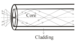
If more than one mode is transmitted through optical fiber, then it is called multimode fiber.
The larger core radii of multimode fibers make it easier to launch optical power into the fiber and facilitate the end to end connection of similar powers.
Optical fiber configuration
Depending on the refractive index profile of fiber and modes of fiber there exists three types of optical fiber configurations:
- Single mode step index fiber
- Multimode step index fiber
- Multimode graded index fiber
Single mode step index fiber
In single mode step index fiber it consists of central core that is sufficiently small so that there is one path for light ray through the cable. The light ray is propagated in the fiber through reflections.
Single mode fiber is known as monomode fiber.
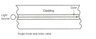
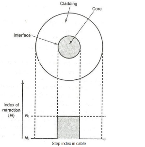
The core fiber of the single mode is narrow compared to the wavelength of kight being used. Therefore, only a single path exists through the cable core through which light can travel.
Multimode step index fiber
In multimode step index fiber the core diameter is 50 to 100 µm that is larger aperture and allows more light to enter the cable.
The light rays are propagated down the core in zig-zag pattern . There are multiple paths that a light ray may follow during the propagation.

Multimode step index fiber
The light rays passing through the fiber are continuously reflected off the glass cladding towards the center of the core at different angles and lengths limiting overall bandwidth.
Multi mode graded index fiber
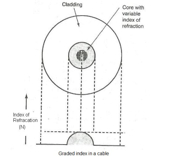
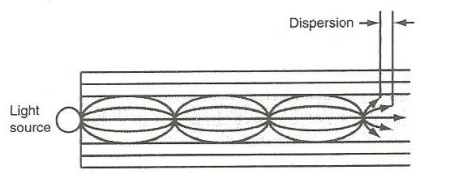
The core size of multimode graded index fiber’s cable varies from 50 to 100 µm range. The light ray is propagated through refraction. The light ray enters the fiber at many different angles.
As the light propagates across the core toward the center it intersects a less dense to more dense medium. Therefore, the light rays are being constantly being refracted and ray is bending continuously. This cable is mostly used for long distance communication.
Problem
A multimode step index fiber with core diameter of 80µm and relative index difference is 1.5% is operating at a wavelength of 0.85µm. If the core refractive index is 1.48 . Estimate
- The normalized for the frequency for the fiber.
- The number of guided modes.
Given data:
- = 0.85 x 10⁻⁶
a = 40 x 10-6
n1 = 1.48

- The normalized frequency may be obtained using
V = 2π/  a n1 (2
  ½
½
V = 2π x 40 x 10-6 x 1.48 ( 2 x 0.015 ) ½ / 0.85 x 10 -6
V = 70.8
- The total number of guided modes is given by
Ms = V 2 /2 = 5745.6/2 = 2873.
Calculate the number of modes of an optical fiber having diameter of 50 µ m , n1 = 1.48 , n2 =1.46 and  = 0.846
Numerical aperture = (n1 2 – n2 2) ½
N.A = (1.48 2 – 1.46 2) ½
N.A = 0.243
The number of modes are given by
Ms = V 2 / 2
Normalized frequency is given by
V = 2π/  a( n1 2 - n2 2
  ½
½
V = = 2π/  a [ NA]
V = 2π/ 0.82 x 10 -6 x 25 x 10 -6 x 0.243
V =46.549
Ms = V2 /2 = 1083
Mode theory for circular wave guides
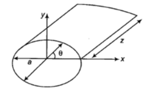
- A waveguide with a circular cross-section is called as Circular Waveguide. It supports both transverse electric (TE) and transverse magnetic (TM) modes. TE11 is the dominant mode in a circular waveguide i.e., a signal in this mode propagates with the minimum degradation.
- The cut-off frequency of a circular waveguide is inversely proportional to its radius.

The vector Helmholtz wave equation for TE and TM wave travelling in a z-direction in a circular waveguide is given by

Circular Waveguide
TE modes:
The Helmholta equation of Hz in circular guide is given as

TEmn modes in circular wave guides is given as

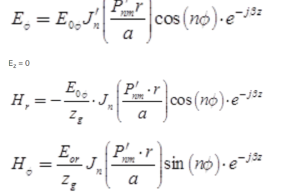

Zg = Er / H = - E/Hr represent characteristic wave impedance in the guide.
Where n = 0 ,1, 2, 3……………..
m= 1,2,3,4
The first subscript n represents number of full cycles of field varaition in one revolution through 2 π radian of , while the second subscript m indicates the number of zeros of E along the radius of the guide.
β= [w 2 µ - (P ‘nm/a) 2 ] ½

The phase velocity, group velocity and guide wave length remains same as that of rectangular waveguide
TM modes:
The TMnm mode in circular guide are defined as Hz =0. But Ez ≠ 0 in order to transmit energy in the guide .
Helmholtz equation in terms of Ez in circular guide is

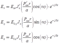
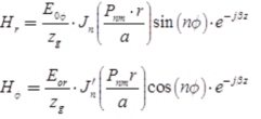
The field equation for TMnm modes are given as
Hz = 0
H = Pnm/a ; n = 0,1,2, 3 and m = 1,2,3,4
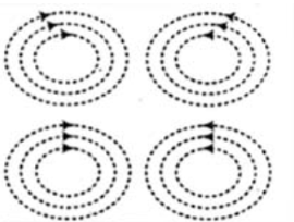
TE 01 mode in circular waveguide
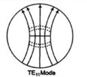
Different TE11 mode of circular waveguide.
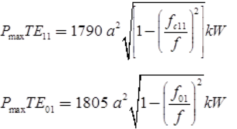
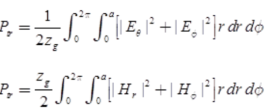
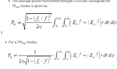
Power transmission in Circular Waveguide
For a loss dielectric
z = Er/H = - E/Hr
Wave impedance in guide.
Single mode fiber:
In a fiber, if only one mode is transmitted through it, then it is said to be a single mode fiber.
• A typical single mode fiber may have a core radius of 3 μm and a numerical aperture of 0.1 at a wavelength of 0.8 μm.
• The condition for the single mode operation is given by the V number of the fiber which is defined as such that V ≤ 2.405.
• Here, n1 = refractive index of the core; a = radius of the core; λ = wavelength of the light propagating through the fiber; Δ = relative refractive indices difference.

Single mode
Features
- Only one path is available.
- V-number is less than 2.405
- Core diameter is small
- No dispersion
- Higher band width (1000 MHz)
- Used for long haul communication
- Fabrication is difficult and costly
Graded index fiber structure
Graded Index fiber is another type of optical fiber in which the refractive index of the core is non-uniform. This non-uniformity is present because the refractive index is higher at the axis of the core and continuously reduces with the radial movement away from the axis.
However, the refractive index of the cladding is constant in the case of graded index fiber. Hence, the nature of the refractive index of the core is somewhat parabolic.
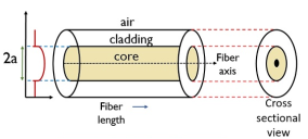
In this type of fiber, the light ray experiences refraction thus gets bent towards the core. Hence, allowing propagation of ray in a curved path.
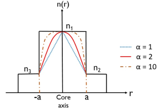
The refractive index of graded index fiber in the mathematical term is expressed as:

a is the radius of the core
r is the radial distance from the core axis.
α shows characteristic of the refractive index profile
n1 and n2 are the refractive indices of core and cladding respectively.
The curve is shown below that represents the variation in the profile of the refractive index with various values of α:
Problem:
A graded index fiber with a parabolic reflective index profile core has a refractive index at the core axis of 1.5 and relative index difference of 1%. Estimate the maximum possible core diameter which allows single mode operation at a wavelength of 1.3 µm.
The maximum value of normalized frequency is given by
2.4 
The maximum core is obtained by a = V  / 2π n1 (2
 ½
½
V = 2.4  x 1.3 x 10 -6 / 2π x 1.5 x (0.02) 1/2
A = 3.3 µm
Hence, the maximum core which allows single mode operation is approximately 6.6µm
Problem:
Estimate the cut-off wavelength for step index fiber in single mode operation.The core refractive index is 1.46 and the core radius is 4.5 µm. The relative index difference is 0.25 %.
Given n=1.46 a = 4.5 x 10 -6  = 0.0025
Cut-off wavelength =
 c = 2π a n1 (2
 ½/ Vc
½/ Vc
For cut=off wave length Vc = 2.405
 c = 1.214 µm.
The signal degradation in optical fiber are:
Attenuation:-
Attenuation is a loss of optical energy as it travels through fibre.It is measured in terms of dB/km.
It is a transmission loss that can be measured as a difference between output signal power and input signal power.It is measured in dB as
Attenuation loss α=10log10(Pin/Pout)/L dB/km
Attenuation is caused both by scattering and absorption.
Absorption:-
Absorption is a phenomenon in which the energy of an atom is absorbed by the matter.Thus the light energy is transformed to other form of energy
For example to heat.
Absorption is of four kinds:-
- Intrinsic absorption:-
- The reason of intrinsic absorption is basic fibre material properties.If an optical fibre is truely pure with no impurities or imperfections then absorption is intrinsic.
- The causes of intrinsic absorption are material and electron absorption.
- Material absorption:-
- It is a loss mechanism which results in dissipation of the transmitted power into heat.
- Electron absorption:-
- Intrinsic absorption in the ultraviolet region is caused by electronic absorption.
- It occurs when a photon absorbs energy from an electron and excites it to a higher level.
- The effect of intrinsic absorption can be minimized using a suitable core cladding materials.
- Extrinsic absorption
It is caused due to the impurities in the material.- Metal impurities such as iron nickel and chromium are introduced in the fibre during fabrication.
- It also occurs due to the presence of hydroxyl ions due to presence of water vapour.
- Extrinsic absorption can be reduced by glass refining techniques such as vapour oxidation and by using a glass fiber called dry fiber which reduces the OH ion concentration.
Optical Sources
There are two commonly· used optical sources for generating the light pulses.
These are light emitting diode (LED) and Laser Diode (LD).
Laser diode with its version as injection-laser diode (ILD) is commonly employed.
Both the sources funnel the light pulses into the fiber-optic medium where they transmit themselves down the fiber cable and are placed in very close proximity to the light emitting region to couple as much light as possible into the fiber.
Light Emitting Diodes
- Light emitting diodes are semiconductor devices that emit visible light when an electric current passes through it in a forward direction.
- When several LEDs are placed side-by-side, they can create pictures. In most of the LEDs, light may be considered monochromatic having single wavelength.
- These wavelengths may range from 700 nanometers to 400 nanometers (red to blue-violet). Some LEDs also emit infrared IR (830 nanometers or longer). These are known as an Infrared Emitting Diode (IRED).
- Light from a Light Emitting Diode (LED) is created in much the same way that light is created in a fluorescent tube or neon sign. In an LED crystal the electrons of its atoms are pumped up to higher energy states, and when they fall back down again, each atom gives off a particle/wave of light. However, the electrons in an LED are not exactly the same as the gas molecules in a neon sign.
- It consists of P-type semiconductor and N-type semiconductor. These two elements are placed in direct contact, forming a region called the P-N junction which usually resembles a semiconductor diode but differs in the size and shape of P-N junction area in addition to transparent package so that visible or IR light may pass through.
- When LEDs are compared with incandescent and fluorescent illuminating devices, its benefits may be looked into low power requirement, high efficiency, long life etc. The applications include indicator lights, LCD panel back lighting, fiber optic data transmission, remote control, optoisolators etc.
Laser Diode:
Laser diodes find extensive use in fiber optic communication systems, compact disc (CD) players, laser printers, remote-control devices etc. There are other conventional lasers based upon helium-neon .
Laser diodes have several advantages over conventional lasers - they are smaller in size and less in weight, have low power requirements, low intensity, wide-angle beam etc.
ILDs have very small light emitting surfaces and can couple many times more power to the fiber than LEDs. The characteristics of ILDs can be seen into linear response of light output versus electrical current input.
They are not stable over wide operating temperature ranges and require more elaborate circuitry to achieve acceptable stability and are therefore costly. These are useful for situations that require the transmission of signals over long distances.
The optical light, which is getting into optical fiber, is a function of a number of factors.
- Intensity
The design of the optical source plays a major role in deciding the intensity and is usually specified in terms of total power output at a particular drive current.
- Area
The amount of light emitted and injected into fiber depends on the light emitting surface compared to the area of the light accepting core of the fiber and it is inversely proportional the area.
- Acceptance Angle
- The aperture of fiber will also decide how much energy can be allowed to enter into the fiber. The injection of light at the aperture of the core at a particular angle will certainly play a crucial role because the transmission of light through the fiber cable follows the principle of total internal reflection.
- If the acceptance angle is more than a specified angle the light getting incident upon fiber may not pass through it. Therefore, the acceptance angle of a fiber, which is expressed in terms of numeric aperture (NA), must lie between a specified range of angles.
- Typical values for numerical Aperture (NA) are 0.1-0.4, which correspond to acceptance angles of 11°-46°. The numerical aperture (NA) is defined as the sine of one half of the acceptance angle of the fiber.
Photo detectors are used primarily as an optical receiver to convert light into electricity. The principle that applies to photo detectors is the photoelectric effect, which is the effect on a circuit due to light.
Max Planck In 1900 discovered that energy is radiated in small discrete units called quanta; he also discovered a universal constant of nature which is known as the Planck’s constant. Planck’s discoveries lead to a new form of physics known as quantum mechanics and the photoelectric effect E = hv which is Planck constant multiplied by the frequency of radiation.
The photo electric effect is the effect of light on a surface of metal in a vacuum, the result is electrons being ejected from the surface this explains the principle theory of light energy that allows photo detectors to operate.
Photo detectors are commonly used as safety devices in homes in the form of a smoke detector, also in conjunction with other optical devices to form security systems.
A photo detector operates by converting light signals that hit the junction to a voltage or current. The junction uses an illumination window with an anti-reflect coating to absorb the light photons. The result of the absorption of photons is the creation of electron-hole pairs in the depletion region.
Examples of photo detectors are photodiodes and phototransistors. Other optical devices similar to photo detectors are solar cells which also absorb light and turn it into energy.
Common Photodetectors
There are different photodetectors:
- Photomultipliers,
- Pyroelectric detectors,
In semiconductor-based photoconductors,
- Phototransistors, and photodiodes.
The most common semiconductor photo detector is the PIN photodiode.
References:
- Fundamentals of fiber optic communication by Satish Kumar.
- Optical Fiber Communications Principles and Practice by John Senior