Unit 2
Light Wave Systems

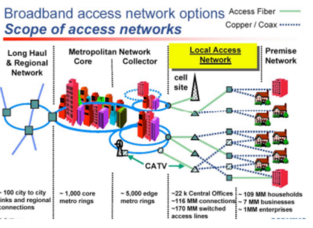
Broadband access network referred as “broadband internet”, is a high data transmission rate Internet connection. DSL and cable modem, which are popular consumer broadband access technologies, are typically capable of transmitting faster than a dial-up modem.
From an architectural standpoint it is classified as
- Point to point links
- Distribution Networks
- Local Area Networks
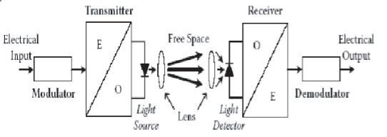
The simplest transmission link is a point-to-point line having a transmitter at one end and a receiver on the other as shown below:

Simple point to point link
This type of link places the least demand on optical fiber technology and thus sets the basis for examining more complex system architecture.
The design of an optical link involves many interrelated variables among the fiber source and photo detector operating characteristics so that the actual link design and analysis may require several iterations before they are completed satisfactorily.
Since the performance and cost constraints are very important factors in fiber optic communication, links the designer must carefully choose the components to ensure the desired performance level can be maintained over the expected system lifetime.
System Requirements
The key system requirements that are needed in analyzing link :
- The desired transmission distance
- The data rate or channel bandwidth
- The BER
To fulfill these requirements the designer has the choice of the following components and their associated characteristics .
- Multimode or single mode optical fiber
- Core size
- Core refractive index
- Bandwidth
- Attenuation
- Numerical Aperture
- LED or laser diode optical source
- Emission wavelength
- Spectral time width
- Output power
- Effective radiating area
- Emission pattern
- Pin or Avalanche photodiode
- Responsivity
- Operating wavelength
- Speed
- Sensitivity
Two analyses are usually carried out to ensure that the demand system performance can be met. These are link power budget and system real time budget analysis.
In the link power budget analysis one first determine the power margin between the optical transmitter output and the minimum receiver sensitivity needed to establish a specified BER. This margin is allocated to connector slices fiber losses etc.
A rise time budget analysis is a convenient method for determining the dispersion limitation of an optical fiber link. This is particularly useful for digital systems.
- Optical Power Budget
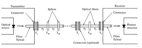
An optical power loss model for a point- to -point link is as shown in the figure. The optical power received at the photo detector depends upon the amount of light coupled into the fiber and the losses occurring in the fiber and at the connector and splices.
The link loss budget is derived from the sequential loss contribution of each elements in the link. Each of these loss elements is expressed as
Loss = 10 log Pout/Pin-----------------(1)
Where Pin and Pout are the optical powers. Entering and leaving the loss element respectively.
In addition to the link loss contributors as shown in the figure a link power margin is normally in the analysis to allow for component aging , temperature fluctuations and losses arising from the component that might be added at future date.
A link margin of 6 to 8 db is generally for systems that are not expected to have additional components incorporated into the link in the future.

Optical power loss model
The link loss budget considers the total optically power loss PT is allowed between the light source and the photo detector and allocates this loss to the cable attenuation, connector loss and system margin. Thus , if Ps is the optical power emerging from the end of the fiber fly lead attached to the light source or from a source coupled connector and if Pr is the receiver sensitivity then
Pr = Ps - PR
PT = 2lc + αL + system margin
Here is the connector loss , αis the fiber attenuation (db/Km) , ‘L’ is the transmission distance and the system margin is normally taken as 6db or 8db
Here we assume that the cable of length ‘L’ has connectors only on the ends and none in between. The splice loss in incorporated into the cable loss for simplicity.
Design an optical fiber link for transmitting 15Mb/sec of data for a distance of 4km with BER of 10-9 .
BW x length of the fiber = 15 x 4 = 60 Mb/s. Km
- Selecting optical source: LED at 820nm is suitable for short distance so the LED generates -10dbm optical power.
- Selecting Optical detector: PIN FET optical detector is equal to reliable and has -50dbm sensitivity.
- Selecting Optical fiber: step index multimode fiber is selected. The fiber has bandwidth length product of 100Mb/s.km.
Assuming :
Splicing loss(lsp) = 0.5 db/slice
Connector loss (lc)= 1.5 db
System margin (Pm)= 8db
Fiber attenuation(α) = 6db/km
Actual loss = 2lc + αL + Pm
= 2x1.5 + 6x4+ 8
Actual loss = 35db
Maximum allowable system loss = optical source output power – optical receiver sensitivity
Pmax = -10 dbm –(-50dbm)
Pmax = 40 dbm
In a fiber link the laser diode output power is 5dbm source-fibre coupling loss = db connector loss of 2db and has 50 splices of 0.1 db loss. Fiber attenuation loss for 100Km is 25db. Compute the loss margin for
- APD receiver with sensitivity -40dbm
- Hybrid PINFET high impedance receiver with sensitivity -32dbm
Power Budget calculations:
Source output power ----------------- 5dBm
Source fiber coupling loss --------- 3db
Connector loss ------------------- 2db
Splicing loss -----------------------5db
Fiber attenuation ----------------------- 25db
Total loss --------------------------------------- 35db
Available power in receiver :Ps –Pr = 5-35 = -30dbm
APD receiver sensitivity =-40dbm
Loss margin = [-40-(-30)] = 10db
Hybrid –PINFET high impedance receiver =-32dBm
Loss margin= [-32 –(-30)]
Loss margin = -2db
- Rise-Time Budget
Rise time gives important information for initial system design. Rise time budget analysis and determines the dispersion limitation of an optical fiber link
Total rise time of a fiber link is the root-sum square of rise time of each contribution to the pulse rise time degradation.
Tsys = [tr1 2 + tr2 2 + tr3 2] 1/2
Tsys =  2 ] ½
2 ] ½
The link components must be switched fast enough and the fibre dispersion must be low enough to meet the bandwidth requirements of the application.
As the light source and detectors has a finite response time to inputs . The device does not turn –on or turn-off instantenously.
The rise and fall time determines the overall response time hence the bandwidth.
The four basic elements that contribute to the rise time are :
Transmitter rise time(ttx)
Group velocity Dispersion (GVD)
Modal dispersion rise time of fiber(tmod)
Receiver rise time (trx)
Receiver rise time :
Tsys = [t 2 tx + t 2 mod + t2 GvD + t 2 rx ] ½ ------------------(3)
Rise time due to modal dispersion is given as
Tmod = 440/BM = 440 L q /B0 --------------------------------------(A)
Where
Bm = bandwidth (MHz)
L = length of fiber (km)
q = parameter ranging between 0.5 and 1
B0 = bandwidth of 1km length fiber
Rise time due to group velocity dispersion is
tGVD = D  L -------------------------------------------------------(B)
Where
D is dispersion [ns/nm.km]
 half power spectral width of the source
L is the length of the fibre.
Receiver front-end rise time in nano seconds is
Trx = 350/Brx
Where
Brx is 3db bandwidth of the receiver
Now eq(3) can be written as
Tsys = [ t 2 tx + (440 L q /Bo) 2 + D2  2 L2 + (350/Brx)] ½ in ns.
Now the system bandwidth is given by
BW = 0.35/tsys
Example
A fiber link has the following data :
Component | Bandwidth | Rise time(tr) |
Transmitter | 200 Mhz | 1.75 nsec |
LED(850nm) | 100 Mhz | 3.50 nsec |
Fiber cable | 90 MHz | 3.89 nsec |
PIN detector | 350 MHz | 1.00 nsec |
Receiver | 180 MHz | 1.94 nsec |
Compute system rise time and Bandwidth
System rise time is given by
Tsys =[  2 ] ½
2 ] ½
Tsys = [t 2 tx + t 2 os + t 2 mod + t 2 GVD + t 2 rx ] ½
Tsys = 1.75 2 + 3.5 2 + 3.89 2 + 1.00 2 + 1.94 2 ] ½
Tsys = 5.93 nsec.
System Bandwidth is given by
BW = 0.35/tsys
BW = 0.35 / 5.93 x 10 -9
BW = 59MHz
- Long Haul Systems
- The Flashwave long-haul system lets service providers achieve maximum through-put over their existing fiber networks for long- and short-haul applications by bringing together time-division multiplexing and dense wavelength-division multiplexing.
- The Flashwave 320G long-haul system supports up to 32 channels of OC-48 (2.5 Gbits/sec) and/or OC-192 (10 Gbits/sec) over conventional singlemode fiber of non-zero dispersion-shifted fiber to transmit 320 Gbits/sec total capacity.
- The short-haul Flashwave Metro system supports 16 channels of OC-48 for a maximum of 40 Gbits/sec using 16 narrowband optical cards. Optical amplifiers can extend the distance as needed.
References
- Fundamentals of fiber optic communication by Satish Kumar.
- Optical Fiber Communications Principles and Practice by John Senior.