UNIT 3
Multichannel Systems
The original optical fiber links that were deployed around 1980 consisted of simple point to point correction . These links contained a single fiber with one light source at the transmitting end and one photo detector at the receiving end.
In these early systems signals from different light sources used separate and uniquely assigned optical fibers. Since the spectral width of a typical laser source occupies only a narrow slice of optical bandwidth these simplex systems greatly under utilize the large bandwidth of a fiber.
The first use of WDM was to upgrade the capacity of installed point to point transmission links. This was achieved with wavelength that were separated from several tens up to 200 nanometers in order not to impose strict wavelength tolerance requirements on the different laser sources and the receiving wavelength separating components at the receiving end.
For implementing WDM various passive and active components are required to combine, distribute, isolate and to amplify optical power at different wavelength.
Passive components are used to split or combine optical signals.
These components operates in optical domains. Passive components do not require external control for their operation. Passive components are fabricated by using optical fibers by planar optical waveguides. Commonly required passive components are
- N x N couplers
- Power splitters
- Power taps
- Star couplers.
Most passive components are derived from basic stat couplers. Stat coupler is used for combining and splitting of optical power. Therefore, star coupler is a multiple input and multiple output port devices.
2x 2 fiber coupler
A device with two inputs and two outputs is called as 2 x 2 couplers. The figure shows a 2x2 coupler .The input and the output port has a long tapered section of length “L”
The tapered section is gradually reduced and fused together to form coupling region of length ‘W’.
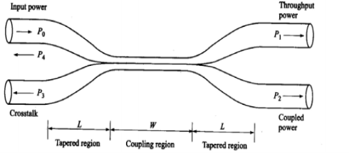
- Po is the input power , P1 is the throughout power and P2 is the power coupled into the second fiber. The parameters P3 and P4 are extremely low signal resulting from backward reflection and scattering.
- As the input light propagates along the taper in fiber 1 and into the coupling region W , there is a significant decrease in the V number owing to the reduction in the ratio r/
 where r is the reduced fiber radius.
 - As the signal enter the coupling region an increasingly larger portion of the input field now propagates outside the core of the fibre. Depending on the dimension of the coupling region any desired fraction of this decoupled field can be recoupled into the other fiber. These devices are known as directional couplers.
- The optical power coupled from one fiber to another can be varied through three parameters:
- The axial length of the coupling region
- The size of the reduced radius r in the coupling region
- The difference
 r in the radii of the two other fibers in the coupling region.
The coupling length is normally fixed so that L and r change as the coupler is elongated. Typical values of W and L are a few millimeters  r/r is around 0.015.
Performance Parameters
- Splitting ratio /coupling ratio
It is the ratio of coupled power to the total output power.
Splitting ratio = P2/P1+P2 x 100 %
- Excess loss
Excess loss is defined as the ratio of the input power to the total output power. It is expressed in decibels.
Excess loss = 10 log Po/P1 +P2
- Insertion Loss
Insertion loss refers to the loss for a particular port to port path. For path from input port “i” to output port “j” .
Insertion loss = 10 log Pi/Pj
- Cross Talk
It is a measure of degree of isolation between the input port and power scattered or reflected back to the other input port.
Cross Talk = 10 log P3/Po.
Example :
For a 2x2 fiber coupler input power is 200µW ,throughput power is 90 µW coupled power is 85 µW and cross talk power is 6.3 µW. Compute the performance parameters of the fiber coupler.
Given data :
Po = 200µW, P1 = 90µW, P2 = 85 µW and P3 = 6.3 µW
Coupling ratio = P2/(P1 + P2) x 100% = 85/90+85 X 100 = 48.57%
Coupling ratio = P2/P1+P2 x100 = 85/90 +85 x 100 = 48.57%
Excess Ratio = 10 log (P0/P1+P2) = 10log (200/ 90+85) = 0.5799
Insertion loss = 10 log (200/90) = 3.46 dB [port 0 to port 1]
Insertion loss = 10 log (200/85) = 3.71 dB [ port 0 to port 2]
Cross Talk = 10 log P3/P0 = 10 log 6.3 x 10 -3 /200 = -45dB.
Star coupler is mainly used for combining optical powers from N-inputs and divide them equally at M –output ports.
The fiber fusion technique is popuraly used for producing NxN star couplers.
Star Coupler:
The star coupler is mainly used for combining optical power from N-inputs and divide them equally at M-output ports.
The fiber fusion technique is used for practicing Nx N star coupler.
The optical power put into any port to one side of coupler is equally divided among the output ports . Ports on same side of coupler are isolated from each other.
The total loss in star coupler is constituted by splitting loss and excel loss.
Splitting loss = -10 log 1/N = 10log N
Excess loss = 10 log [ Pin /
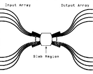
8 x 8 star coupler
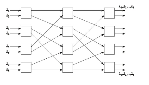
8 x 8 star coupler can be formed by interconnecting 2x2 couplers. It requires twelve 2x2 couplers.
Excess loss in dB = -10 log [Fr log 2 N ] -----------------------(1)
Splitting loss = 10 log N --------------------------(2)
Total loss = splitting loss + Excess loss
Total loss = 10 (1-3.2 log FT) log N----------------------(3)
Problem:
A 32 x 32 star coupler is formed by interconnecting 2x2 couplers. If 5% of power is lost in each coupler element. Calculate the total loss in coupler.
Given
N = 32
FT =100 -5/100 = 0.95
Total loss = 10(1-3.32 log FT) log 32 = 16.16 dB.
Optical Isolator and Circulator
Optical Isolators are devices that allow light to pass through them in only one direction. This is important in number of instances to prevent scattered or reflected light from travelling in reverse direction.
The core of the device consists of 450 Farady rotator that is placed between two wedge shaped birefringent plates.
Light travelling in forward direction is separated into ordinary and extra ordinary rays by first birefringent plate.
The Faraday rotator then rotates the polarization plane of each ray by 45 0 and then it is passed over Birefringent plate. The axis of these two rays maintains the same.
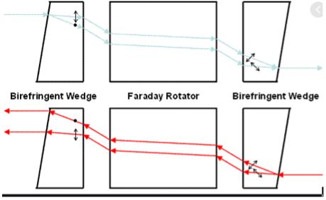
Design and operation of a polarization independent isolator made of three miniature optical components.
Optical Circulator
An optical circulator is a non-reciprocal multiport passive device that directs light sequentially from port to port in only one direction. This device is used in optical amplifiers
Add/drop multiplexers and dispersion compensation modules.
The operation of circulator is similar to that of an isolator except that the construction is more complex. Typically it consists of a number of walk-off polarizer’s, halfwave plates and faraday rotates and has three to four ports
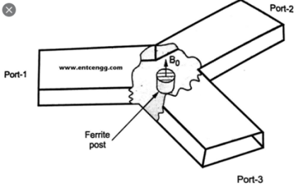
Operation of three port circulator
To see how it works consider the three port circulator . Here an input port on port 1 is sent out on port 2 , an input on port 2 is sent out on port3 and an input on port 3 is sent out on port1.
Multiplexers and De-multiplexers
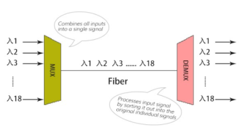
WDM uses wavelengths to increase bandwidth by multiplexing various optical carrier signals onto a single optical fiber. It combines a series of optical carrier signals with different wavelengths carrying various information and coupled to the same optical fiber for transmission at the transmitting end.
At the receiving end, a demultiplexer separates optical signals of various wavelengths. This technique of simultaneously transmitting two or many different wavelengths in the same fiber is called wavelength division multiplexing, or WDM.
Depending on the direction of the transmitted signal, WDM can be used for multiplexing or de-multiplexing.
Fiber Bragg Grating
Fiber Bragg Gratings are developed by laterally exposing the core of a single-mode fiber to a periodic pattern of intense laser light.
This exposure produces a permanent increase in the refractive index of the fiber’s core, creating a fixed index modulation according to the exposure pattern. This fixed index modulation is called grating.
At each periodic refraction change a small amount of light is reflected. All the reflected light signals combine coherently to one large reflection at a particular wavelength when the grating period is approximately half the input light’s wavelength.
This is referred to as the Bragg condition, and the wavelength at which this reflection occurs is called the Bragg wavelength. Light signals at wavelengths other than the Bragg wavelength, which are not phase matched, are essentially transparent. This principle is shown in the figure.
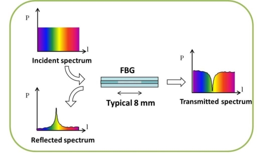
Therefore, light propagates through the grating with negligible attenuation or signal variation. Only those wavelengths that satisfy the Bragg condition are affected and strongly back-reflected. The ability to accurately preset and maintain the grating wavelength is a fundamental feature and advantage of fiber Bragg gratings.
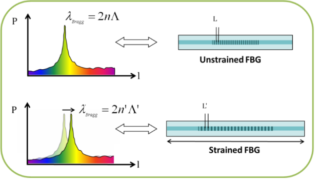
The central wavelength of the reflected component satisfies the Bragg relation: λBragg = 2nΛ, with n the index of refraction and Λ the period of the index of refraction variation of the FBG.
Due to the temperature and strain dependence of the parameters n and Λ, the wavelength of the reflected component will also change as function of temperature and/or strain, as shown in figure.
This dependency helps in determining the temperature or strain from the reflected FBG wavelength.
FBG application for multiplexing and de-multiplexing function :
A MUX/DEMUX device uses selective wavelength filtering with the help of chirped fiber Bragg gratings. In order to selectively filter several wavelengths at the same time FBG’s are replaced bby a single chirped fiber Bragg gratings with the required bandwidth leading to better performance and reduced complexity of MUX/DEMUX configurations.
Multiplexer configuration
A wavelength MUX is an optical filter that combines signals at different wavelengths arriving at input ports into a single signal at the output port . This feature is implemented with chirped fiber Bragg gratings and optical circulators as shown in figure. The four wavelengths are joined from separate input ports into a common output port.
The advantage of this is broad reflection bandwidth in order to redirect the wavelength channels to the output port . There is no need of individual gratings at the input port for each wavelength.
Each input port is illuminated with a broadband optical source and optical spectrum analyzer placed at the output port in order to measure the spectral response of different filters.
The output power for each channel varies because the reflectivity of each CFBG is not 100% and each channel has different optical path as they suffer circular insertion losses.

Optical multiplier for 4 channels Spectral response
De-multiplexing configuration:
A wavelength DEMUX is an optical device that separates a signal containing multiple wavelength arriving at an input port into several wavelength at the output ports performing opposite function of the multiplexer.
The DEMUX configuration is in essence the mirror of the MUX configuration except that the direction of light through the optical circulators have been reversed.
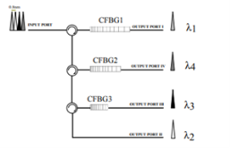
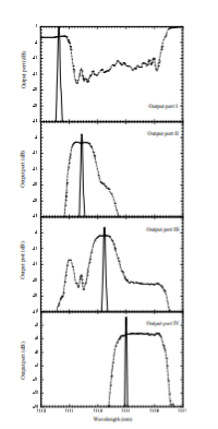
The DEMUX implemented splits the incoming signal into four different wavelength at each output port . The spectral response and the channel wavelength at each output port of DEMUX is shown in the figure.
The spectral response, for each output is obtained from optical source launched into the input port and the channel wavelength which is acquired from four wavelengths launched into the input port of DEMUX.
Due to channel wavelength acquired from four wavelengths which is launched into the input port of DEMUX.
Diffraction Gratings
A diffraction grating is an optical surface in which a large number of grooves are located. The grating has the property of diffracting light in a direction related to its wavelength as shown in the figure. Hence, an incident beam with several wavelengths is angularly separated into different directions.
Several wavelengths O1, O2, ... coming from different directions can be combined into the same direction. The diffraction angle depends on the groove spacing and on the incidence angle.
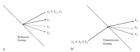
Principle of de-multiplexing by diffraction of optical grating: wavelengths  1,
1,  2,
2,  3 coming froma single transmission fiber are diffracted into different directions The diffraction grating works in reflection (a) or in transmission (b)
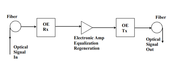
- In order to transmit signals over long distance it is necessary to compensate for attenuation losses within the fiber.
- Initially thus was accomplished by with optoelectronic module consisting of an optical receiver , a regeneration and equalization system and an optical transmitter to send data.
- Even though it functions, it is restricted to optical to electrical and electrical to optical conversions.
SOA
Service-Oriented Architecture (SOA) is an architectural approach in which applications make use of services available in the network. In this architecture, services are provided to form applications, through a communication call over the internet.
- SOA allows users to combine a large number of facilities from existing services to form applications.
- SOA encompasses a set of design principles that structure system development and provide means for integrating components into a coherent and decentralized system.
- SOA based computing packages functionalities into a set of interoperable services, which has to be integrated into different software systems belonging to separate business domains.
There are two major roles within Service-oriented Architecture:
- Service provider: The service provider is the maintainer of the service and the organization that makes available one or more services for others to use. To advertise services, the provider can publish them in a registry, together with a service contract that specifies the nature of the service, how to use it, the requirements for the service, and the fees charged.
- Service consumer: The service consumer can locate the service metadata in the registry and develop the required client components to bind and use the service.

The services aggregate information and data retrieved from other services or create workflows of services to satisfy the request of a given service consumer. This practice is known as service orchestration.
Another important interaction pattern is service choreography, which is the coordinated interaction of services without a single point of control.
EDFA
Erbium Doped Fiber (EDF)is a conventional silica fiber doped with erbium. Basically, EDFA consists of a length of EDF, a pump laser, and a WDM combiner.
The WDM combiner is for combining the signal and pump wavelength so that they can propagate simultaneously through the EDF.
It can be designed such that pump energy propagates in the same direction as the signal (forward pumping), or the opposite direction to the signal (backward pumping), or both direction together.
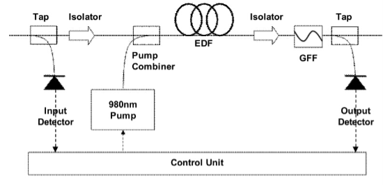
- When transmitting over a long distance, the signal is highly attenuated. Therefore there lies a need to implement an optical signal amplification to restore the optical power budget.
- That is the reason EDFA commonly used for especially it is designed to directly amplify an input optical signal, which eliminates the need to first transform it to an electronic signal.
- It can amplify all WDM channels together.
- At present EDFA rises as a preferable option for signal amplification method for WDM systems, owing to its low-noise and insensitive to signal polarization.
- Besides, EDFA deployment is relatively easier to realize compared with other signal amplification methods.
RFA
Due to a lot of losses which the signal suffers from, such as fiber loss, splice loss, etc, in optical fiber communication system the signal becomes weak. Thus, it is necessary to use amplifier with good gain and low NF to compensate all losses occur in the fiber, to transmit signals over long distances.
To transmit multiple signals in the same fiber and increase the information capacities of a fiber system, Wavelength Division Multiplexing (WDM) technique is used.
Raman fiber amplifier (RFA) can be used to amplify data channels at any band, the amplification in every type of fiber, the ability to provide gain at any wavelength by using the proper pumping scheme by adjusting the pump wavelengths , multiple pump
Wavelengths can be used to increase the amplification bandwidth, and wide gain bandwidth. Thus, L-band optical amplifier is better to adopt RFA rather than L-band EDFA ]. The gain bandwidth is only limited by the available pump powers and wavelengths, flat gain
Bandwidths up to 100 nm can be achieved.
References
- Optical Fiber Communications: Principles and Practice John M Senior
- Optical Fiber Communications by Gerd Keiser.