UNIT 2
Switching Networks and Signaling
- A single stage of switching elements (SEs) exists between the inputs and the outputs of the network.
- The simplest switching element that can be used is the 2 X 2 switching element (SE). Figure illustrates the four possible settings that an SE can assume.
- Straight; the upper input is transferred to the upper output and the lower input is transferred to the lower output.
- Exchange; the upper input is transferred to the lower output and the lower input is transferred to the upper output.
- Upper-broadcast; the upper input is broadcast to both the upper and the lower outputs.
- Lower-broadcast; the lower input is broadcast to both the upper and the lower outputs.
- To establish communication between a given input (source) to a given output (destination), data has to be circulated a number of times around the network.
- A well-known connection pattern for interconnecting the inputs and the outputs of a single-stage network is the Shuffle-Exchange.
- Two operations are used.
- Shuffle;
- Exchange;
- Two operations are used.
With shuffle (S) and exchange (E) operations, data is circulated from input to output until it reaches its destination.
- If the number of inputs, for example, processors, in a single-stage IN is N and the number of outputs, for example, memories, is N, the number of SEs in a stage is N/2. The maximum length of a path from an input to an output in the network, measured by the number of SEs along the path, is Log2(N).
- Example: In an 8-input single stage Shuffle-Exchange if the source is 0(000) and the destination is 6(110), then the following is the required sequence of Shuffle/ Exchange operations and circulation of data:
E(000) 1(001) S(001) 2(010) E(010) 3(001) S(001) 6(110)
The network complexity of the single-stage interconnection network is O(N) and the time complexity is O(N) .
- Grading is the limiting of the number of outlets that in incoming call (into an exchange) can be switched to. Grading only occurs in exchanges setup for Limited Availability.
- It limits the available outgoing lines that the incoming lines can switch to in an exchange.
- This technique was once a major statistical endeavor undertaken for almost all exchanges; advancements in technology however have started to make the use of grading obsolete, due to modern technology allowing for all exchanges to be fully available.
A link is a communication channel that connects two or more devices. The link may be a dedicated physical link or a logical link that uses one or more physical links or shares a physical link with other telecommunications links.
A telecommunications link is generally based on one of several types of information transmission paths such as those provided by communication satellites, terrestrial radio communications infrastructure and computer networks to connect two or more points.
Uplink
An uplink (UL or U/L) is the portion of a feeder link used for the transmission of signals from an earth station to a space radio station, space radio system or high altitude platform station.
Downlink
A downlink (DL or D/L) is the portion of a feeder link used for the transmission of signals from a space radio station, space radio system or high altitude platform station to an earth station.
Forward Link
A forward link is the link from a fixed location (e.g., a base station) to a mobile user. If the link includes a communications relay satellite, the forward link will consist of both an uplink (base station to satellite) and a downlink .
Reverse link
The reverse link (sometimes called a return channel) is the link from a mobile user to a fixed base station.
In telephone field, the so called busy hour traffic are used for planning purposes. Once the statistical properties of the traffic are known, the objective for the performance of a switching system should be stated. This is done by specifying a grade of service (GOS). GOS is a measure of congestion expressed as the probability that a call will be blocked or delayed. Thus when dealing with GOS in traffic engineering, the clear understanding of blocking criteria, delay criteria and congestion are essential.
Measure of GOS.
- GOS is expressed as a probability.
- The GOS of 2% (0.02) mean that98% of the calls will reach a called instrument if it is free. Generally, GOS is quoted as P.02 or simply P02 to represent a network busy probability of 0.02. GOS is applied to a terminal-to terminal connection.
- For the system connection many switching centres, the system is generally broken into following components.
(i) an internal call (calling subscriber to switching office)
(ii) an outgoing call to the trunk network (switching office to trunk)
(iii) The trunk network (trunk to trunk)
(iv) A terminating call (switching office to called subscriber)
- Thus, the traffic analysis is the fundamental request for the design of cost effective, efficient and effective configuration of networks.
- The effectiveness of a network can be evaluated in terms of how much traffic it carries under normal or average loads and how often the traffic volume exceeds the capacity of the network.
- Fundamental problem in the design of telecommunication networks concerns the dimensioning of a route. To dimension the route, volume of traffic required grade of service and capacity (in bits per sec) must be known.

Where A0 = carried traffic A = offered traffic A – A0 = lost traffic. The smaller the value of grade of service, the better is the service.
SPACE DIVISION SWITCHING
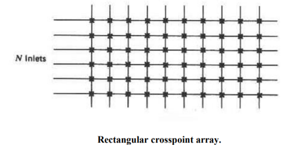
This switching matrix can be used to connect any one of Ninlets to any one of M outlets. If the inlets and outlets are connected to two-wire circuits, only one crosspoint per connection is required.1 Rectangular crosspoint arrays are designed to provide intergroup (transit) connections only, that is, from an inlet group to an outlet group. Applications for this type of an operation occur in the following: 1. Remote concentrators 2. Call distributors 3. Portion of a PBX or end office switch that provides transit switching 4. Single stages in multiple-stage switches
TIME DIVISION SWITCHING
Time division switching is equally applicable to either analog or digital signals. At one time, analog time division switching was attractive when interfacing to analog transmission facilities, since the signals are only sampled and not digitally encoded. However, large analog time division switches had the same limitations as do analog time division transmission links: the PAM samples are particularly vulnerable to noise, distortion, and crosstalk. Thus, large electronic switching matrices have always incorporated the cost of digitizing PAM samples to maintain end-to-end signal quality. The low cost of codecs and the prevalence of digital trunk interconnections imply that analog switching is now used in only the smallest of switching systems (e.g., electronic key systems).
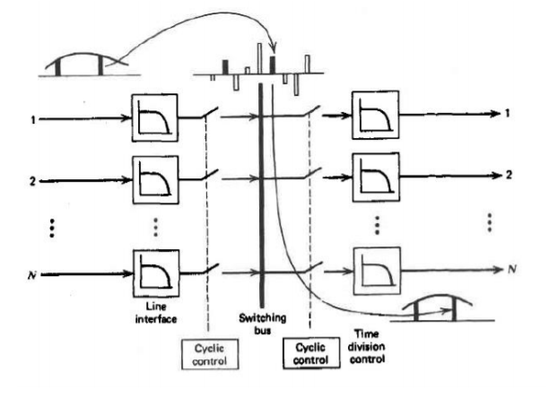
- It provides the switching paths between the called subscribers and the calling subscribers.
- The main advantage of time division time multiplexing technique is that, unlike time division space switching, it allows time slot interchange (TSI) of sample values. In TSI, a speech sample input during a time slot may be sent to the output during a different time slot, which implies a delay between reception and transmission of a sample.
- The rate at which the time slot clock runs is 125-$\mu$ sec. The time slot counter increments by one, at the end of each clock pulse, the contents of which provide location addresses for data memory and control memory. The input sample is read at the beginning of the time slot and it is clocked at the end of the clock pulse. Because of the storage action, the sample is delayed at least by a single time slot in passing from the input to the output, even if there is no time slot interchange.
- A TSI which can be expanding or concentrating has different number of time slots per frame at input and output also. For an expanding switch, the output bit rate is higher, whereas for a concentrating switch, the input bit rate is higher. The handling of input and output subscribers in this technique can be done in four ways, such as serial-in/serial-out, parallel-in/parallel-out, serial-in/parallel-out, parallel-in/serial-out.
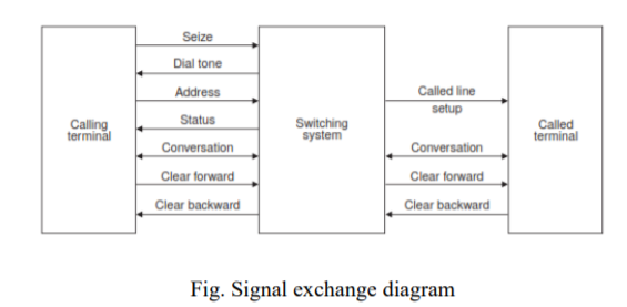
In this section, the basic steps involved in processing a call is discussed. Most digital system follow a similar scheme. For any switching system design, the range of signals that has to be interchanged between a terminal and system is considered. These signals described in signal exchange diagram. The sequence of operation between subscribers and system are shown in state transition diagram (s.t.d.).
Basic Steps to Process a Call The sequence of processing between subscribers are described below:
1. Idle state. At this state, the subscriber handset is in ‘on-hook’ condition. The exchange is ready to detect the call request from the subscriber.
2. Call request identification. The exchange identifies a line requiring for a service. When the handset is lifted, current flows in the line called seize signal indicates the call request.
3. Providing dial tone. Once the seize signal is received, an exchange sends a dial tone to the calling subscriber to dial the numbers.
4. Address analysis. Once the first digit received, the exchange removes the dial tone and collect all numbers. Then the address is analysed for the validity of the number, local, STD or ISD etc. If the number is invalid, a recorded message may be sent to the calling subscriber and terminates call request.
5. Called line identification. The exchange determines the required outgoing line termination from the address that it has received.
6. Status of called subscriber. The called line may be busy or free or unavailable or even out of service. In the case of PBX, where the customer have a group of lines, the exchange tests each termination until either it finds a free one or all one found busy. For busy, number unobtainable or the handset off hook, a status signal or call progress signal is sent to the calling subscribers for line termination. Now the exchange resumes idle state.
7. Ringing. Once, the exchange finds the called subscriber is free, power ringing is provided to the called subscriber and audible ringing to the calling subscriber.
8. Path setup. When the called subscriber lifts his handset, the line is looped and ringing is removed. Once the conversation started, the exchange completes the connections between the subscribers.
9. Supervision. The exchange supervises the connection to detect the end of the call for charging.
10. Clear signal. Once the need for connection is over, either customer may replace his handset. It causes the line current seize and provides a clear signal to exchange. If the calling subscriber replaces his phone set, the clear signal sent to the exchange is called clear forward signal. If called subscriber do first, the clear signal is called clear backward signal.
Low level control
- This level associated with subscriber lines, trunks, selective circuits, Input/output controller and digital subsystems.
- The line terminating module and trunk modules are microprocessor based and communicate with subsystems through the input/output controllers.
- The input/output controllers interpret the incoming messages and takes necessary actions and communicate to the network control processors.
- All subscriber lines connected to digital switching system through the main distributing frame (MDF) are continuously scanned to detect the state of the subscriber.
- When the customer lifts his handset, the line scanning program detects this state and reports to the input/output controller.
- At this level, all the requests of incoming and outgoing trunks are handled. Any advanced features to be incorporated in a digital switching system also handled at this level using IOC.
Mid-level control
- This level is associated with network control processors and associated circuits.
- The IOC is controlled by the network control processors (NCP). Many NCP’s are used depends on the size of the digital switching system.
- A dedicated bus system is usually required for the processors to communicate with one another. Specific messaging protocols are used to communicate between processors.
- For messaging between the peripherals and external systems, many digital switching systems utilize standard protocols such as signalling system 7(SS7); X.25 and X.75.
- Thus this is the most important level of control any digital switching system. Distributed processing are performed at this level.
High level control
- This level associated with central processor which organizes the entire network control sub processors.
- In includes many subsystems like call accounting subsystems (CAS), call processing subsystems (CPS).
- Digital switching subsystems (DSS).Digital subscriber’s switching subsystem (DSSS), Local administration (LA), maintenance control subsystems (MCS); management statistics subsystems (MSS), message transmission subsystems (MTS), signal interworking subsystems etc.
- This central processor is normally a main frame type computers. Thus all basic controls of a digital switching system are incorporated at this level.
A signaling system link the variety of switching system, transmission systems and subscriber equipment in a telecommunication network to enable the network to function as a whole. The signaling are classified according to the internal signaling of an exchange, signaling between exchanges and signaling between an exchange and subscriber. Thus a signaling system must be obviously be compatible with the switching systems which itself partitioned into subsystems in a network.
- Carrier systems are mechanisms that provide a means to send signals from more than one source over a single physical channel. The bandwidth available to carry signals in a particular medium can be allocated in two ways: by frequency or by time intervals.
- The frequency spectrum represented by the available bandwidth of a channel can be divided into smaller bandwidth portions, with each of several signal sources assigned to each portion. This is the principle of frequency-division multiplexing (FDM). FDM is still used in some simple data communications systems, and, at one time, it formed the foundation for the long-haul part of the public telephone network. One common example of a frequency-division multiplexing system is a standard low-speed (300bps) modem, which divides the spectrum available in a voice channel into two portions—one for transmitting and one for receiving.
- The electronic mechanisms that implemented FDM are called analog carrier systems. The carrier in an analog carrier system is a signal generated by the system, and the carrier is modulated by the signal containing the information to be transmitted.
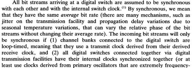
In PCM systems, signaling and speech are sampled, coded and transmitted within the frame of PCM channels. Thus, with PCM, a convenient way of transmission is possible. The signaling information and speech information carried in the same time slot is referred as in slot signaling. The signaling information carried in a separate time slot is referred as out slot signaling. The timeslot of the in slot signaling is fixed at eight bits. As one bit is used for signaling, the speech bit rate is reduced to 56 kbps from 64 kbps and the bandwidth is reduced. Telephone channels are combined by time division multiplexing to form an assembly of 24 or 30 channels. This is known as primary multiplex group. Two frame structures are widely used in practice. They are DS1 24 channel system and European 30 channel system. DS1 24 channel system is popular in North America and Japan. Originally, DS1 is called as T1 system. T1 (Telecommunication standards entity number 1) is a standards committee designated as ANSI T1-nnn-date. T1 uses some very specific conventions to transmit information between both ends. One of these is a framing sequence that formats the samples of voice or data transmission. Framing undergone several evolutions.
Registers are utilized in common control exchanges to store and analyze routing data.
They are given on a common basis is a single register gives routing data for a number of speech circuits. When a call has been setup, the register is after that made available to set up another calls. And inter register refers to signaling among two registers of dissimilar exchanging.
Signaling systems link the type of transmission systems, subscriber equipments and switching systems in telecommunication network to allow the network to function as an entire. Three types of signaling are included in a telecommunication network as:
1. Subscriber loops signaling
2. Intra exchange or register signaling
3. Interexchange or inter register signaling
In a telephone network, subscriber loop signaling depends on the kind of a telephone instrument utilized. The inter exchange signaling is internal to the switching system and is heavily dependent on the type and design of a switching system. This varies from one model to other even with similar manufacturer. Such signaling does not include signaling system of the type needed on the switching network. If interexchange signaling takes place in between exchanges along with common control subsystems, this is termed as Inter register signaling.
The main reason of Inter register signaling is the exchange of address digits that pass from exchange to exchange upon a link by link basis. Also network wide signaling includes end to end signaling among the originating exchange and the terminating exchange. This form of signaling is termed as line signaling. CCS does not utilize the speech or the data path for signaling. This uses a separate common channel, for passing control signals for information paths or a group of trunks.
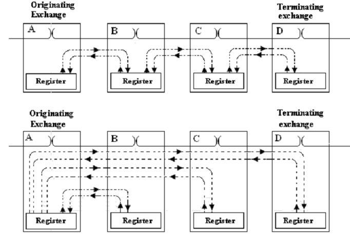
FIG - End-to-end Signaling
For multi link connection in a network of register that controlled exchanges, a register into the originating exchange gets address information by the calling customer and sends out routing digits. All succeeding registers, receives and sends out both routing digits, till the terminating exchange is reached. Such sequence of operation introduces post-dialing delay.
An inter-register signaling system cannot be utilized for seize, clear and answer signals. No register is connected while an incoming seize signal is received, because this is the signal that initiate a connection to a register. The register is released after this has set up a connection by its exchange and sent out routing digits; therefore, this cannot get answer and clear signals.
Therefore, no signal is sent out till the complete address information has been got. In overlap signaling, digits are sent out immediately as possible. Therefore, some digits may be sent before the complete address has been acquired and signaling may take place before the complete address has been received and signaling may take place concurrently on two links (that is the signal overlap).
The enables next registers to start digit to analyses previous than is possible along with en-bloc signaling and it reduces post-dialing delay. Also link-by- link signaling or end-to-end signaling may be utilized. In the link-by-link signaling, information exchange only among adjacent registers in a multi link connection as demonstrated by figure. In end-to-end signaling, the originating register controls the setting up of a connection till this reaches its last destination, as demonstrated in figure.
Each transit register receives simply the address information needed to select the outgoing route to the subsequent exchange in the connection. Containing performed its task, this is released and the originating register signals to the subsequent register.
Common Channel Signaling uses a separate common channel for passing control signals for a group of trunks or information paths as it does not use the speech or the data path for signaling. The common channel signaling consists of two types of nodes such as Signaling Transfer Points (STP) and Signaling Points (SP).
A Signaling point is capable of handling control messages directly addressed to it but is incapable of routing messages. Signaling transfer point is capable of routing messages and can perform the functions of SP.
This common channel signaling is implemented in two modes −
- Channel associated mode
- Channel non-associated mode
Channel-associated Mode
In the channel-associated mode, the channel closely tracks the trunk groups along the entire length of the connection. Here, the signaling is done on a separate channel; the signaling path passes through the same set of switches, as does the speech path.
The following figure shows the associated mode of operation in common channel signaling:
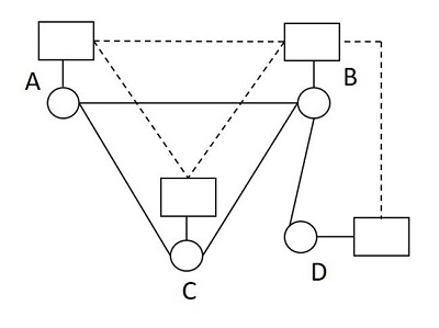
The signaling paths for the speech paths A-B, A-C-B and B-D are A-B, A-C-B and B-D respectively. The advantages of this signaling are −
- The implementation is economic
- The assignment of trunk groups is simple
Channel Non-associated Mode
- In the channel non-associated mode, there is no close or simple assignment of the control channels to trunk groups. It follows a different path from that of the speech signal as shown in the following figure.
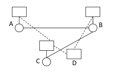
- The signaling paths for the speech paths A-B and B-C are A-C-D-B and B-D-C respectively. The network topologies are different for signaling and speech networks. Though this scheme offers flexibility as there is no switching center, it is a bit complex, as the signal messages may be transferred between the two end switching systems via any available path in the common channel signaling network according to its own routing principles.
Advantages:
1. For each associated trunk group, only one set of signaling facility is required. The channel used for CCS need not be associated with any particular group. Fig. Shows a CCS network that is disassociated from the message network structure.
2. The introduction of SPC switching machines and CCS provides efficient routing procedure.
3. CCS allows for signaling at any time in the entire duration of a call, not only at the beginning.
4. CCS removes most of the signaling costs associated with inter office trunks.
5. Information can be exchanged between processor at high speed.
Disadvantages:
1. The CCS network is basically a store and forward network. So, in a established circuit, the signaling information are stored, processed and then forwarded to next node. This causes additional overhead and disconnect to the continuity.
2. If one node fails to transmit properly, the facilities downstream from the disconnect will not be released. Thus, a high degree of reliability is required for the common channel.
3. Proper interfacing facility is necessary, as most of the present day telephone networks are equipment with in channel signaling systems.
4. As the signaling information is not actually sent over speech paths in CCS, the integrity of speech path is not assured. As a remedy, routing testing of idle paths and the continuity test of an established path become necessary in CCS.
- CCITT Signaling System No. 6 was the first CCS system to be implemented internationally.
- It was originally designed for use in the international network, but some flexibility is included to allow its use in national networks.
- It is an inter-exchange signaling system. CCITT No. 6 has been implemented widely, but it is now being superseded by CCITT No. 7.
- CCITT No. 6 offers a wide range of features associated with being a CCS system, including operation in the quasi-associated mode, error detection and correction mechanisms and re routing capabilities in fault conditions.
- However, its main drawback is its limited evolutionary potential. In a dynamic environment, CCITT No. 7 offers far greater flexibility and evolutionary capability, particularly due to its structured architecture.
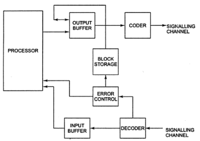
- CCITT Signaling System No. 7 (SS No. 7) was developed to meet the stringent signaling requirements of the all‐digital network based on the 64‐kbps channel. It must provide for supervision of circuits and address signaling, and carry call progress signals and alerting notification to be eventually passed to the called subscriber. CCITT No. 7 is a data network entirely dedicated to inter switch signaling and is described as an international standardized common‐channel signaling system.
- It is a set of telephony signaling protocols developed in 1975, which is used to set up and tear down telephone calls in most parts of the world-wide public switched telephone network (PSTN). The protocol also performs number translation, local number portability, prepaid billing, Short Message Service (SMS), and other services.SS7 uses common channel signaling, in which the path and facility used by the signaling is separate and distinct from the signaling without first seizing a voice channel, leading to significant savings and performance increases in both signaling and channel usage.
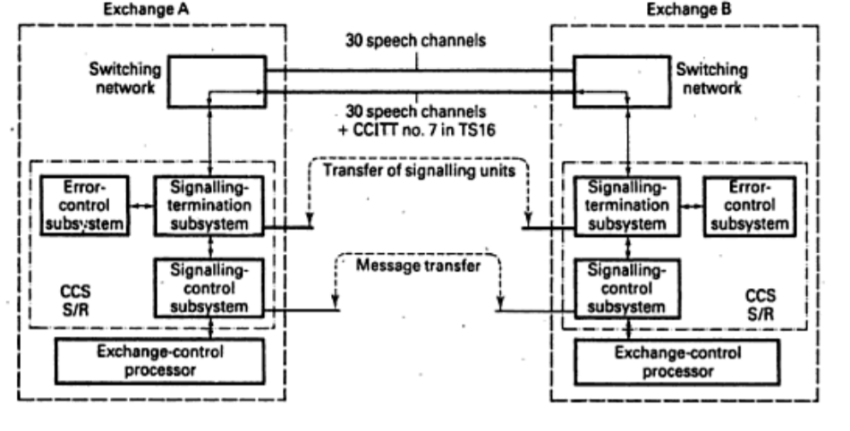
Digital transmission is used on customers lines to provide to an ISDN. Each line may give access to several terminals on the customer’s premises and common channel signaling is used to serve them.
Basic rates provide two B channels at 64 Kbit/s and a D channel at 16 kbit/s for signaling. Primary rate access provides, 30 channels or 23 channels, together with a 64kbit/s signaling D channel.
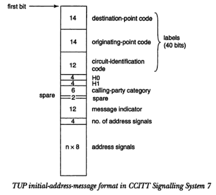
The CCITT has defined the digital subscriber signalling no.1 for signalling over the D channel. The transfer of information in each direction between the customer’s premises and the exchange is by messages called frames.
Similar to CCITT no. 7 signal units. The control fields indicates the type of frame being transmitted.
There are three types of frames:
- I format for information transfer
- S format for supervisory transfer
- U format for un numbered transfer
References
1. Theodore S Rappaport, “Wireless Communications Principles and Practice” Second Edition, Pearson Education
2. John C. Bellamy, “Digital Telephony”, Third Edition; Wiley Publications
3. ThiagarajanVishwanathan, “Telecommunication Switching Systems and Networks”; PHI Publications
4. Wayne Tomasi, “Electronic Communications Systems”; 5th Edition; Pearson Education
5. Vijay K Garg, Joseph E Wilkes, “Principles and Applications of GSM” Pearson Education
6. Vijay K Garg, Joseph E Wilkes, “IS-95CDMA and CDMA 2000 Cellular/PCS Systems Implementation” Pearson Education
7. Mischa Schwartz, “Mobile Wireless Communications”, Cambridge University Press