UNIT 4
First and Second Generation Mobile Systems
- Every wired or wireless system is basically an analog system.
- 1G was widely deployed in 1980s and if is still used in many corner of world even after replacement of it have been done by digital cellular system.
- Samuel Morse started work in 1838 for telegraph network, it was now reached to different stage of communication.
- Best standard from Bell Labs for Advanced Mobile Phone System (AMPS) was popular in 1970s.
- On basis of AMPS standard, first commercial phone in Japan deployed in 1979.
- On basis of AMPS standard first commercial phone in US deployed in 1983.
- Total access communication system (TACS) standard, similar to AMPS it has high frequency and low bandwidth channel. Services of TACS extended to U.K. Known as ETACS.
In 1989, Japan deployed JTACS, i.e. has some variation to TACS. It work in slightly higher frequency;
Table
Sr. No. | Technologies/ standard | Country |
1 | Nordic Mobile Technology | Scandanavia |
2 | Radiocom 2000 | France |
3 | C – 450 | Germany and Portugal |
- Many standards found among European countries for analog system which further lead to generate need for uniform standard as well as frequency allocation to whole Europe.
Advanced mobile phone system (AMPS) was a standard for analog cellular phone system developed by Bell Labs and officially introduced by AT&T in 1983.
Features
- It is an analog system based on the initial electromagnetic spectrum allocation for cellular service by the Federal Communications Commission.
- It uses frequency division multiple access (FDMA) for multiple simultaneous conversations.
- Frequency ranges within the 800 and 900 MHz are allocated for cellular telephones in AMPS. Half of the signal is used for sending signals and half is used for receiving signals.
- It has a high bandwidth requirement particularly when the number of conversations is very high.
- It was the first system to use hexagonal cells. So, the pioneers of AMPS had coined the term coined cellular.
- The cells in AMPS are 10km to 20 km across.
- Since, it was an analog technology, it suffered from noise and eavesdropping.
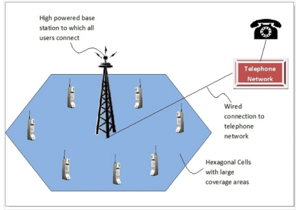
- GSM is one of the most successful and popular mobile telecommunication standard. Global System for Mobile communication (GSM) is a 2G communication standard with the frequency ranges of 900, 1800 and 1900 MHz.
- GSM has initially been deployed in Europe and its main aim is to provide a mobile system that can provide the voice service compatible to the other PSTN and ISDN systems.
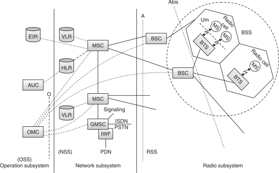
Fig. : GSM Architecture
A GSM system consists of three subsystems :
 1. Radio Sub System (RSS)
2. Network and Switching Subsystem (NSS)
3. Operation Sub System (OSS)
Radio Sub System
In GSM network all radio specific entities are comprised in radio sub systems. RSS consists the two main entities as :
 (i) Mobile Station (MS)
(ii) Base Station System
The basic function of RSS is to connect the mobile station to the network. The RSS can consists a number of Base Station Controller (BSC) and each BSC connects to the number of Base Transceiver Systems (BTS) and each BTS connects to a number of mobile stations (MS).
(i) Mobile Station (MS)
A Mobile Station (MS) consists of several functional groups.
(a) Mobile Terminal (MT)
Mobile Terminal offers common functions used by all services. MT transmits through the interface Um.
(b) TA (Terminal Adapter)
Terminal adaptation hides the radio specific characteristics.
(c) Terminal equipment (TE)
A user terminal through which the user receives and sends the data. It can be a headset, microphone etc.
(d) SIM (Subscriber Identity Module)
It is a card inserted into the MS. SIM uniquely identifies the user to the services, stores user parameters and enables the MS to connect to the GSM network.
(ii) Base Station Subsystem (BSS)
BSS have two main components :
(a) Base transceiver station
It connects to a number of mobile stations. The connection between the MS and BTS is established through the Um user interface. Main functions performed by BTS are as follows :
(i) Processing of signals
(ii) Formation of cells
(iii) Amplification of signals
(iv) Frequency hopping
(v) Channel coding and decoding
(vi) Encryption and decryption of data.

Fig.: MS and BTS connection through Um in GSM cell
(b) Base station controller
It manages a number of BTSS. It uses the Abis interface to connect to various BTSs main functions performed by BSC are as follows :
(i) Processing of signals
(ii) Switching between BTSs
(iii) Controlling BTSs
(iv) Reserving radio frequencies
(v) Frequency hopping and paging.
(vi) Authentication, encryption and decryption of data.
Network and Switching Subsystem (NSS)
- NSS can be considered as the heart of the GSM system. The NSS connects the wireless network with standard public network.
- Switching, mobility management, interconnection to other network, system control are some main work of NSS.
The NSS consists of the following databases and switches :
(i) Mobile Services Switching Center (MSC)
- There are mainly high-performance digital ISDN switches. They used to set up the connections to other MSCs and to the BSCs over the A interface.
- The main aim of MSCs is to manage the various BSCs in a geographical region. The various functions performed by MSC are as follows :
(i) Establish the connections to other fined network, such as PSTN and ISDN via Gateway MSC (GMSC) or Interworking functions (IWF).
(ii) Handles all signaling needed for connection setup, connection release and handover of different connections to the other MSCs.
(iii) Call monitoring of MS.
(iv) Supplementary service support such as call forwarding multi-party calls.
(ii) Gateway Mobile Service Switching Centre (GMSC)
This is a MSC which handles connections to other networks like ISDN, PSTN, PSPDN.
(iii) Home Location Register (HLR)
- HLR is important database in a GSM system that stores all relevant information of user. It stores the Mobile Subscriber ISDN (MSISDN) number, subscribed services such as call forwarding, roaming, GPRS, subscriber’s ISMI, users location Area, Users current VLR and MSC status.
- A unique HLR record is maintained for each mobile user, which is updated on a real-time basis. HLR can manage data for huge number of customers with the help of highly specialized databases.
(iv) Visitor Location Register (VLR)
- VLR is a dynamic database which associated to each MSC.
- VLR is used to stores all important information needed for the mobile station users, such as the current location area (LA) information that is connected to MSC. If a new MS comes into other location area then VLR copies all relevant information of this user from HLR.
Operation Sub System (OSS)
OSS work for the operation and maintenance of the entire network. The main components of OSS are Operation and Maintenance Centre (OMC), Authentication Centre (AuC) and Equipment Identity Register (EIR).
(i) Operation and Maintenance Center (OMC)
- The OMC monitors and controls all other network entities over the O interface.
- Main functions of OMC are management of status reports of network entities, Subscriber security management, traffic monitoring and accounting and billing.
(ii) Authentication Centre (AuC)
- AuC is used by the HLR to authenticate the user, AuC is used to protect user identity and data transmission.
- The AuC used various algorithms for authentication as well as use the keys for encryption and generates the values needed for user authentication in HLR.
(iii) Equipment Identity Register (EIR)
- EIR works as the database for all International Mobile Equipment identity (IMEI), it stores all device identifications registered for this network such as the mobile equipment manufacturer and model.
- Stolen or malfunctioning mobile station can be locked by using the black list of EIR.
- A large group of different network is working on standards provided by GSM.
Table: GSM system frequency bands
GSM standard | Location of using it | Uplink band | Downlink band |
GSM-900 | Europe | 890-915 MHz | 935-960 MHz |
E-GSM 900 | Europe | 880-915 MHz | 925-960 MHz |
DCS-1800 | Europe | 1710-1785 MHz | 1805-1880 MHz |
PCS-1900 | North America | 1850-1910 MHz | 1,930-1,990 MHz |
GSM-400 | Scandinavian |
|
|
| Countries | 450,4 – 457,6 MHz | 460,4-467,6 MHz |
|
| 478.8-486 MHz | 488.8-496 MHz |
GSM-850 | America | 824-849 MHz | 869-894 MHz |
- A wide range of uplink and downlink used for transmission of signals. Signal transmitted from mobile device to network and vice-versa.
- Table 3.3.1 shows band range which support to multiband mobile devices.
- There multiple access methods are used to share resource by users in radio system are :
(i) Frequency Division Multiple Access (FDMA)
(ii) Time Division Multiple Access (TDMA)
(iii) Code Division Multiple Access (CDMA)
- All these three technique divides frequency band, time slides and code in FDMA, TDMA and CDMA respectively.
- In FDMA particularly frequency band divided into several channels. Each channel used to convey radio modulated carriers or signal.
- A pair of uplink channel / downlink channel known as Absolute Radio Frequency Channel (ARFC). Every ARFC has assigned with a number called ARFCN.
- Logical channels used to transmit information of voice, data and signaling. It is further used to set up a call / to adapt link / to manage handovers.
- Logical channel has two types of channel i.e. traffic channel and control channel. Control channel is further divided into four classes.
- Broadcast
- Dedicated
- Common
- Associated
Table
Class of control channel | Logical channel | Uplink/downlink | Role |
Broadcast channel (BCH) | Broadcast control channel (BCCH) | DL | System information broadcast |
| Frequency control channel (FCCH) | DL | Cell frequency synchronization. |
| Synchronization channel (SCH) | DL | Cell time synchronization and identification. |
Common | Paging Channel (PCH) | DL | MS paging |
Control | Random Access Channel (RACH) | UL | MS random access |
Channel | Access Grant Channel (AGCH) | DL | Resource allocation |
(CCCH) | Cell Broadcast Channel (CBCH) | DL | Short message broadcast |
Dedicated control | Standalone dedicated control channel (SDCCH) | UL/DL | General signaling |
Channel | Slow associated control channel (SACCH) | UL/DL | Signaling associated with the TCH |
| Fast associated control channel (FACCH) | UL/DL | Handover signaling |
Traffic channel | Full speech (TCH/FS) | UL/DL | Full-rate voice channel |
(TCH) | Half rate (TCH/HS) | UL/DL | Half rate voice channel |
| 2.4 kbps, 4.8 kbps, 9.6 kbps, 14.4 kbps full rate channels (TCH/F2.4, TCH/F4.8, TCH/F9.6, TCH/F14.4) | UL/DL | Full-rate data channels |
| 2.4 kbps and 4.8 kbps-rate data channels (TCH/H2.4, TCH/H4.8) | UL/DL | Half-rate data channels. |
Some combinations of logical channel on physical channel are as follows :
- TCH/F + FACCH/F + SACCH/TF
- TCH/H + FACCH/H + SACCH/TH
- FCCH + SCH + BCCH + CCCH
- FCCH + SCH + BCCH +CCCH + SDCCH + SACCH
- BCCH + CCCH
- SDCCH + SACCH
- GSM Time Hierarchy is also known as GSM Frame Hierarchy.
- In GSM, frequency band of 25 MHz is divided into 200 KHz of smaller bands.
- Each carry one RF carrier, this gives 125 carriers.
- As one carrier is used as guard channel between GSM and other frequency bands 124 carriers are useful RF channels.
- This division of frequency pool is called FDMA.
- Now each RF carrier will have 8 time slots.
- This division time wise is called TDMA.
- Here each RF carrier frequency is shared between 8 users.
- Hence in GSM system, the basic radio resource is a time slot with duration of about 577 µs.
- This time slot carries 156.25 bits which leads to bit rate of 270.833 kbps.
- This is explained below in TDMA GSM frame structure.
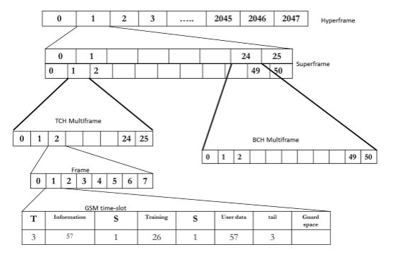
- The GSM frame structure is designated as hyperframe, superframe, multiframe and frame.
- One GSM hyperframe composed of 2048 superframes.
- Each GSM superframe composed of multiframes (either 26 or 51 as described below in Figure 2.1).
- Each GSM multiframe composed of frames (either 51 or 26 based on multiframe type).
- Each frame composed of 8 time slots.
- Hence there will be total of 2715648 TDMA frames available in GSM and the same cycle continues.
- As shown in the Figure 2.1 below, there are two variants to multiframe structure.
I) 26 Frame Multiframe:
It is called as Traffic Multiframe.
It composed of 26 bursts in a duration of 120ms, out of these 24 are used for traffic, one for SACCH and one is not used.
II) 51 Frame Multiframe:
It is called as Control Multiframe.
It composed of 51 bursts in a duration of 235.4 ms.
This type of multiframe is divided into logical channels. These logical channels are time scheduled by BTS.
- Burst is made up of data to be transmitted, training sequence, tail bits as well as guard period.
- There are five types of bursts :
(i) Normal burst
(ii) Frequency correction burst
(iii) Synchronization burst
(iv) Dummy burst
(v) Access burst
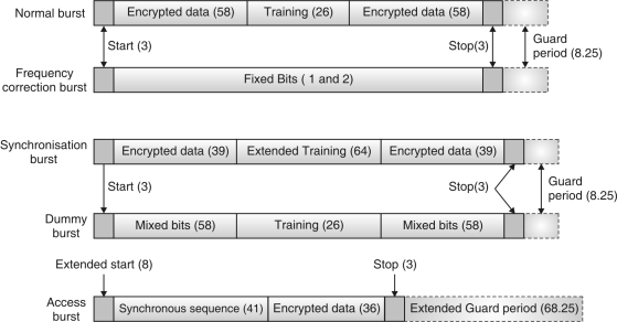
Fig.: Burst types in GSM PLMN
Mobile Terminated Call
Steps
(a) User dials a phone number (another GSM user)
(b) PSTN a fixed network identify number belong to a user in GSM network and forward call setup to appropriate Gateway MSC (GMSC).
(c) The GMSC identify HLR subscriber; to call user by providing setup with HLR.
(d) HLR checks whether number exists, services subscribed to it. It also requests an MSRN from current VLR.
(e) VLR sends MSRN to HLR.
(f) As received to MSRN, the HLR detects responsible MSC of that MS and forward information to GMSC.
(g) GMSC now forward call setup request to MSC indicated.
(h) MSC request VLR to know current status of MS.
(i) VLR send/provide requested information.
(j) If MS found in reach of network MSC initiate a paging in all cells it is responsible for.
(k) The BTSs of BSSs transmit the paging signal to MS.
(l to m) If MS answers or reply, VLR perform security check.
(n to p) Then VLR signals to MSC to setup a connection to MS.
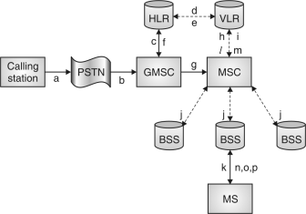
Fig.: Mobile Terminated Call
Mobile Originated Call (MOC)
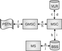
Fig.: Mobile Originated Call
Step (a) MS generate request for new connection.
(b) BSS forward same request to MSC.
(c to d) MSC checks if user allows setting up call with requested and checks availability of resources through GSM network into PSTN.
If all resource available then MSC is set up for establish connection among MS and PSTN (fixed n/w)
Some other messages exchanged for MS and BTS connection on either side are as shown in figure.
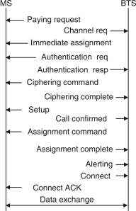
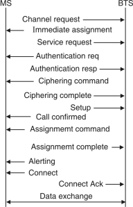
Fig.: Message flow for MTC Fig.: Message flow for MOC
- Geo earth is logically divided into some regions. These regions are considered as cells. Two cells are apart by boundaries in between them.
- Each cell associated with one base station among it. This base station is access point for mobile service. All devices communicate via same access point as if they covered under same base station. Base station connect to wired and wireless network both.
- Every cell is in adjacent in its almost all sides. Adjacent area of base station found differences in frequency, this distinct frequency is essential.
- Equal frequencies lead to generate interference.
- As mobile device users change locations they sometime reach nearby to cell boundaries some moves inside cells too. Even though its service remains without interruption and this is maintained by hand off
- Changing cell activity is maintained by handover to provide services without interruption. Inter – cell handover, inter – MSC handover, inter – BSC handover, inter – BSC and inter – MSC handover, intra – cell handover inter-cell and intra – BSC handover, inter-cell and inter MSC handover are the various handover needed to maintain to provide ongoing communication users mobility.
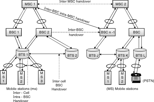
Fig.: Handover in GSM for mobile device, moving from one to another location
MS – Mobile station
BTS – Base transmission station
BSC – Base station controller
MSC – Mobile switching center
- Each cell is 4 to 8 miles in diameter with lower limit around 2 miles. Frequencies can be reused.
- In cellular network GSM and CDMA are competing technology. Most of CDMA users moved to GSM.
- No any single cell can cover entire service area. A group cells are used to cover complete area, so it is possible to reach every subscriber.
- If a subscriber does not get a proper handoff service turn into cut-off or call drop.
- Need of handover
(i) MS moves out of the range provided by cell to that BTS which decreases signal level and on other hand increase error rate.
(ii) Load balance among BSC and MSC.
(iii) Weak links among MS and BTS for uplink and downlink.
Types of GSM Handover
(i) Inter-BTS Handover
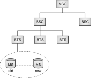
Fig.: Illustration for inter-BTS handover
- Need for change inter-BTS handover based on few parameter like signal strength (dBm), signal quality (BER) at MS down-link. Other parameters like signal strength received from MS, signal quality received from MS at BTS uplink.
- In intra-BTS handover mobile remains connected at same base station transceiver just change in channel or slot.
Inter-BTS Intra BSC Handover
- When a mobile or subscriber changes his location or moves from one BTS area to another under same BSC; an inter-BTS Intra BSC handover takes place.
- Mobile or subscriber gets assigned by a new channel and slot before it release old BTS. So it get uninterrupted service while moving.
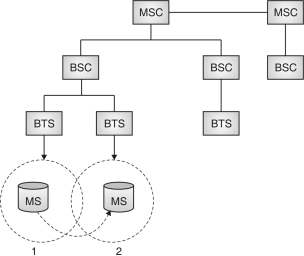
Fig.: Illustration for inter-BTS intra BSC handover
Inter-BSC Handover
- A mobile or subscriber moves out of a range provided by a cell which is under control of one BSC.
- MSC controlled BSC to BSC handover takes place without service interruption.
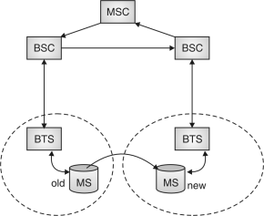
Fig.: Illustration for inter-BSC handover
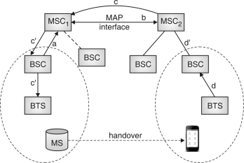 Inter-MSC Handover
Fig. Illustration for Inter-MSC Handover
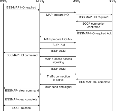
Fig.: Message-cum-interaction between two MSC to handle handover
- When a long displacement mode by a mobile or subscriber a inter-MSC handover takes place.
- Two MSC work to avoid cut-off or call drop while handover task performed.
- Handover in UMTS i.e. in W-CDMA technology having three basic types :
- Hard handover
- Soft handover
- Softer handover
- Reason for handoff failure
- Unavailability of channel on selected BS.
- Lack of resources may lead to deny network.
- Failure of target link during process of handoff execution.
- Long distance network to set up for handoff.
There are three new data services :
 GPRS
GPRS- HSCSD
- DECT
GPRS
- General Packet Radio System (GPRS) is a packet based data services for wireless communication.
- A packet radio principle are used to transfer subscriber data packet within GSM mobile station and external packet data network.
- Data is split and transmitted at sender node and reassembled at receiving end. GPRS support IP and X.25, these operate over cellular connection of a GSM.
- According to peter Rysavy, Rysavy Research 1998 GPRS network is as follows :
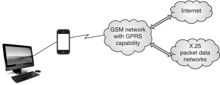
Fig.: GPRS network (1)
- GPRS system has a base of GSM communication and somewhat of circuit switched phone connection, Short Message Service (SMS).
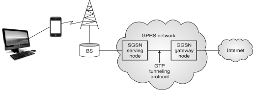
Fig.: GPRS Network (2) (by Peter Rysavy)
Working of GPRS
- SGSN :
It manage to send and receive of packet data to and from MS. It is useful for keeping track of mobile devices within scope of service area. It works in mobility management subscribed user verification and provides data required for billing.
- GGSN :
It has vital role of routing information whichever is necessary for tunneling Protocol Data Unit (PDUs). To SGSN to Serve Distinct MS. It is on interface for external PDNs. i.e. public data units like internet and X.25.
Charging gateway
- It maintain log entries for activities like data being transfer, change in charging terms in peak/off to peak and vice-versa, end of session for GPRS etc.
- It has collection records related to GPRS, usage in buffering of data, storage, transfer of data.
GTP
GPRS tunneling protocol uses to encapsulate IP or X.25 packet which are transferred among SGSN and GGSN.
Application of GPRS
GPRS provides many function among several applications. These are listed below :
- Chat
- Information services as text or graphics.
- Still images.
- Moving images
- Web browsing
- Document sharing and remote collaborative working
- Audio reports
- Job dispatch
- Corporate email
- Vehicle positioning
- File transfer.
HSCSD
- HSCSD stands for high speed circuit switched data. It is enhanced version of circuit switched data, it help to improve error correction in various level of quality of radio links.
- HSCSD provides data rate upto 14.4 kbps by using multiple time slot at same time. It transfer time sensitive images or video at high speed.
- In generate some latency compared to GPRS while in transmission of normal voice and data traffic.
Features
1. High speed circuit switched data technology gives four times faster compare to typical GSM networks.
2. 38.8 kbps speed for all type of non-voice application.
3. It work with multiple slot which makes allow for data transmission at higher rate.
4. With all standard conditions (UL, DL) user can attain 40 to 57.4 kbps in specific area.
DECT
- DECT stands for digital enhanced cordless telecommunication system.
- DECT provides
- A high capacity structured network access.
- It covers flexibility along with identities and addressing.
- It has high spectrum efficiency.
- Implementation can be made over wide variety of terminals.
- Using MC/TDMA/TDD principle for basic DECT a total spectrum nearly of 120 duplex channels is available to a DECT de-vice at any instant location.
References
1. Theodore S Rappaport, “Wireless Communications Principles and Practice” Second Edition, Pearson Education
2. John C. Bellamy, “Digital Telephony”, Third Edition; Wiley Publications
3. ThiagarajanVishwanathan, “Telecommunication Switching Systems and Networks”; PHI Publications
4. Wayne Tomasi, “Electronic Communications Systems”; 5th Edition; Pearson Education
5. Vijay K Garg, Joseph E Wilkes, “Principles and Applications of GSM” Pearson Education
6. Vijay K Garg, Joseph E Wilkes, “IS-95CDMA and CDMA 2000 Cellular/PCS Systems Implementation” Pearson Education
7. Mischa Schwartz, “Mobile Wireless Communications”, Cambridge University Press