Unit – 2
Combinational Logic Design
Digital circuits are divided into two broad categories:
In combinational circuits, the outputs at any instant of time depend on the input present at that instant of time.
In sequential circuits, the outputs at any instant of time depend on the present inputs as well as past inputs/outputs. Which means these circuits contain elements used to store past information. These elements are known as memory.
We will now be studying the design of combinational circuits.
The aim is to design a combinational circuit using logic gates. The number of components used should be minimum to ensure low cost, space saving and power requirements.
One of the traditional approaches to design combinational circuit is by simplifying a given Boolean expression or truth table by using standard methods and then realizing the simplified expression using logic gates.
The following methods to simplify Boolean functions are discussed here:
Any arbitrary logic function can be expressed in the following forms:
Eg: Y(A,B,C,D)= AB+BC +CD ---------- Eq.(1)
Eg: Y(A,B,C,D)= (A+B+D) ( +
+  ) ---------- Eq.(2)
Notice that in Eq.(1) and Eq.(2) , all the individual terms do not involve all the four literals.
If each term in SOP and POS forms contains all the literals then these are known as Standard (or Canonical) SOP and POS.
Thus, a Standard SOP form is one in which a number of product terms, each one of which contains all the variables of the function either in complemented or non-complemented form, are summed together. Each individual product term in standard SOP form is called a minterm.
Eg: Y = ABCD+ABC +
+ CD
CD
A Standard POS form is the one in which a number of sum terms, each one of which contains all the variables of the function either in complemented or in non-complemented form, are multiplied together. Each individual sum term in standard POS form is called a maxterm.
Eg: Y= (A+B+ +D) (
+D) ( +B+
+B+  +D)
+D)
Any given SOP/POS function which is not in its standard form, can always be converted to a standard from by unreducing, that is, “expanding’ the function.
EXPANSION OF A BOOLEAN FUNCTION TO STANDARD SOP FORM
Any SOP equation can be converted to standard SOP by ANDing the terms in the expression with terms formed by ORing the variable and its complement which are not present in that term.
Eg: Convert Y = A + B +AB
+AB +ABCD to standard SOP form.
Solution: Y = A + B +AB
+AB +ABCD
+ABCD
= A(B+ )(C+
)(C+ )(D+
)(D+ ) + B
) + B (A+
(A+ )( D+
)( D+ ) + AB
 (C+
(C+ )
)
= ABCD+ ABC +AB
+AB D +AB
D +AB +A
+A CD+ A
CD+ A C
C +A
+A D +A
D +A +
+  B
B D+
D+ B
B
= m15 + m14 + m13+ m12 + m11+ m10 + m9+ m8 + m5 + m4
= ∑m (15,14,13,12,11,10,9,8,5,4)
NOTE: Each minterm is represented by mi where the subscript i is the decimal equivalent of the natural binary number corresponding to the minterm with uncomplemented variables taken as 1’s and the complemented variables taken as 0’s.
EXPANSION OF A BOOLEAN FUNCTION TO STANDARD POS FORM
Any POS equation can be converted to standard POS by ORing the terms in the expression with terms formed by ANDing the variable and its complement which are not present in that term.
Eg: Convert Y = (A+B)(A+C)(B+ ) to a standard POS form.
Solution: Y = (A+B)(A+C)(B+ )
)
= (A+B+C )(A+B
)(A+B +C) (A
 +B+
+B+ )
)
= (A+B+C)(A+B+ )(A+B+C)(A+
 +C) (A+B+
 )(
)( +B+
+B+ )
)
= (A+B+C) (A+B+ )(A+
)(A+ +C) (
+C) ( +B+
+B+ )
)
= M0 + M1 + M2 + M5
= πM (0,1,2,3)
NOTE: Each maxterm is represented by Mi where the subscript i is the decimal equivalent of the natural binary number corresponding to the maxterm with uncomplemented variables taken as 0’s and the complemented variables taken as 1’s.
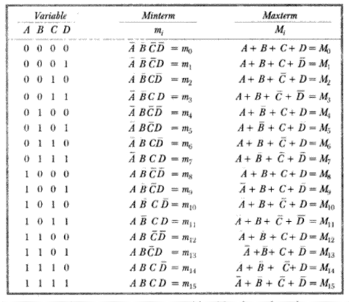
In general, for a n-variable logical function there are 2n minterms and 2n maxterms. The possible minterms/maxterms for a 4-variable function is shown below:
If a logical function is specified in terms of minterms/maxterms its minterm/maxterm representation can be determined using complementary property. For example, for a 4-variable function if:
Y = ∑m (0,3,6,7,10,12,15)
then Y = πM (1,2,4,5,8,9,11,13,14)
Boolean expressions can be simplified algebraically but we can never be sure whether the minimal expression obtained is the real minimal as it depends on the ability to apply Boolean algebraic rules, laws and theorems.
The Karnaugh-Map (K-Map) provides a systematic method for simplifying Boolean expressions. K-Map is an arrangement of adjacent cells that represent the information contained ina truth table or available in POS or SOP form.
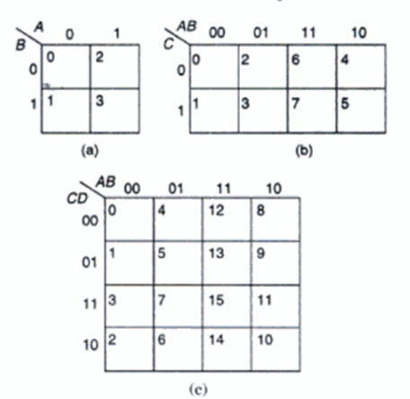
Since the K-Map is a graphical representation of Boolean expressions, a two variable K-Map will have 22 = 4 cells, a three variable map will have 23 = 8 cells and so on. Thus, in a n-variable K-Map there are 2n cells.
The following figures a,b,c show the K-Maps for two, three and four variable functions respectively. Each cell corresponds to one of the combinations of n variables, since there are 2n combinations of n variables. In each map the variables and all possible values of the variables are indicated. The decimal number corresponding to each cell is indicated in the top corner of each cell.
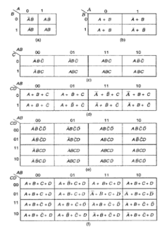
The minterm/maxterm corresponding to each cell and the term is written inside each cell as shown below:
REPRESENTATION OF TRUTH TABLE ON K-MAP
Consider the following truth table of a 3-variable logic function:
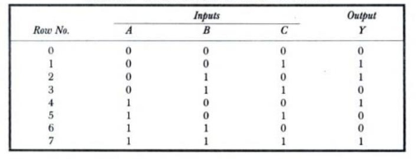
The output Y is logic 1 corresponding to the rows 1,2,4,7. Corresponding to this we can write the equation in terms of standard SOP as:
Y =  C+
C+ B
B +A
+A +ABC
+ABC
Similarly the output Y is Logic 0 corresponding to the rows 0,3,5,6. Therefore the standard POS equation corresponding to the truth table can be written as:
Y= (A+B+C)(A+ +
+ )(
)( +B+
+B+ )(
)( +
+ +C)
+C)
The above two equations are equivalent and represent the truth table given above. The complete K-Map of the truth table is shown below. The value of the output Y (0 or 1) corresponding to its minterm/maxterm identification is entered in each cell.
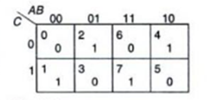
Similarly, if a K-Map is given, the truth table corresponding to it can be made using the reverse process. That is, the output Y is logical 1 corresponding to the decimal numbers/minterms represented by cells with entries 1. In all other rows, the output Y is logical 0.
Thus a logical equation in standard SOP form can be represented on a K-Map by entering 1’s in the cells of the K-Map corresponding to each minterm present in the equation. Similarly, a logical equation in standard POS form can be represented on K-Map by entering 0’s in the cells of the K-Map corresponding to each maxterm present in the equation.
Note: If any equation is not in its standard SOP/POS form, it can be converted into its standard form by the method discussed earlier.
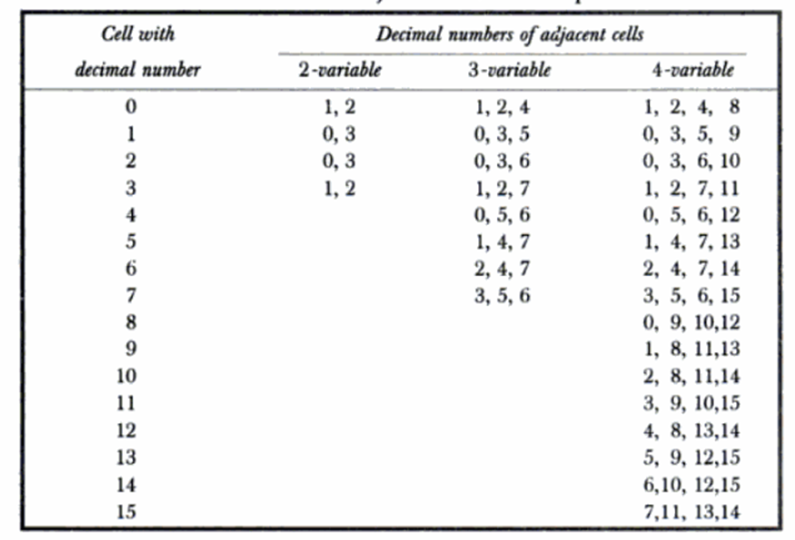
Circuit simplification using K-Maps is achieved based on the principle of combining terms in adjacent cells. Two cells are said to be adjacent if they differ in only one variable. In the K-Maps shown below, the top two cells are adjacent and the bottom two cells are adjacent. Also, the left two cells and the right two cells are adjacent.

The table below gives the adjacent cells of 2, 3 and 4-variable K-Maps.
STEPS TO SIMPLIFY AN EXPRESSION USING K-MAP :
1) Select an appropriate K-Map according to the number of variables.
2) Identify minterms/maxterms as given in problem.
3) To obtain a simplified SOP expression, insert 1’s in the cells of K-Map respective to the minterms.
4) To obtain a simplified POS expression, insert 0’s in the cells of K-Map respective to the maxterms.
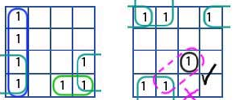
5) Form groups (pairs, quad, octet).
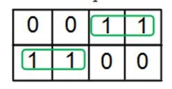
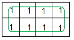
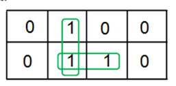
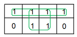
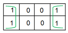
Examples of 3-variable K-Map grouping:

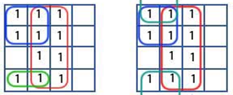
Examples of 4-variable K-Map grouping:
6) Obtain Boolean expression for each group
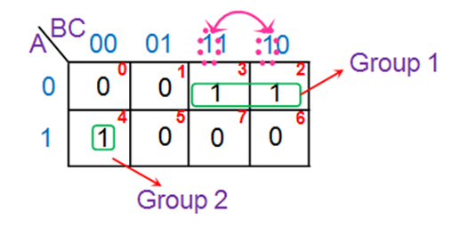
Hence the next term is B. This yields the product term corresponding to this group as A̅B. Similarly the ‘one’ in the Group 2 of the K-map is present in the row for which A = 1. Further the variables corresponding to its column are B̅C̅. Thus one gets the overall product-term for this group as A B̅C̅.
7) Obtain Boolean expression for the output

A few more examples elaborating K-map simplification process are shown below.
Example 1: Simplify the following expression using K-Map.
Y= 
Solution:
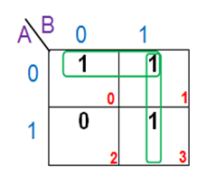
Therefore, simplified expression can be written as: Y= 
Example 2: Simplify the expression: F=∑m (0,2,4,5,6,7)
Solution:
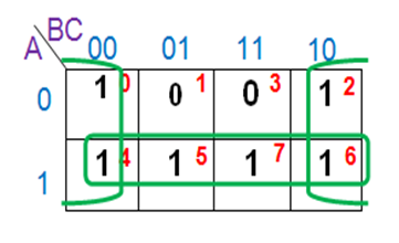
The simplified expression is F = 
Example 3: Simplify the expression F= ∑m(0,2,5,7,8,10,13,15)
Solution:
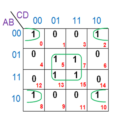
The simplified expression is F= 
Note: In the above discussion we have considered groups of 2, 4, and 8 adjacent ones. Instead of making the groups of ones, we can also make groups of zeros. The procedure is similar to the one used above.
Example 4: Simplify the expression F= π M(1,3,6,7) using K-Maps
Solution:
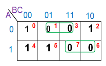
The simplified expression obtained is F= 
Thus, the following important points can be noted:
So far the expressions considered have been completely specified for every combination of input variables. But sometimes, it may so happen that the value of the output is unspecified either because of the input combinations are invalid or because the precise value of the output is of no consequence.
The combinations for which the values of the expressions are not specified are called don’t care combinations, denoted by ‘X’. The output is a don’t care for these input combinations. During the process of design using an SOP map, each don’t care is treated as a 1 if it is helpful in map reduction, otherwise it is treated as a 0 and left alone. During the process of design using a POS map, each don’t care is treated as a 0 if it is useful in map reduction, otherwise it is treated as a 1 and left alone.
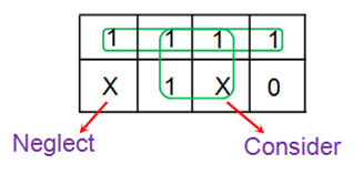
An SOP expression with don’t cares can be converted into a POS form by keeping the don’t cares as they are, and writing the missing minterms of the SOP form as the maxterms of the POS form. Similarly to convert a POS expression with don’t cares into an SOP expression, keep the don’t cares of the POS expression as they are and write the missing maxterms of the POS expression as the minterms of the SOP expression.
Example: Minimize f = m(1,5,6,12,13,14) + d(4) in SOP minimal form
Solution:
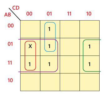
The simplified expression is f= BC' + BD' + A'C'D
Example: Minimize the following function in SOP minimal form using K-Maps: F(A, B, C, D) = m(1, 2, 6, 7, 8, 13, 14, 15) + d(3, 5, 12)
Solution:
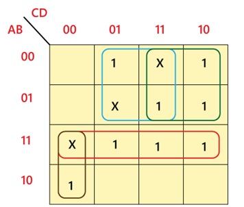
The simplified expression is f= AC'D' + A'D + A'C + AB
(I) ARITHMETIC CIRCUITS
Addition and Subtraction are the two most fundamental arithmetic operations performed on binary numbers. Half Adder and Full Adder are used to perform addition operation on binary data. Similarly, Half Subtractor and Full Subtractor is used to perform subtraction operation on binary data.
THE HALF-ADDER
A half-adder is an arithmetic circuit which performs addition on two input bits and produces results as SUM and CARRY in the output. The block diagram and truth table of the half-adder circuit is shown below:

From the truth table, the Boolean expression for SUM and CARRY can be written as:
Sum= A  B
B
Carry= AB
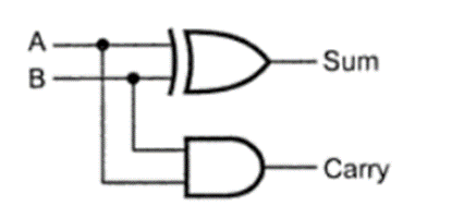
A half-adder can therefore be realized using one XOR Gate and one AND Gate as shown below:
THE FULL-ADDER
A Full-Adder is an arithmetic circuit which performs addition operation on three input bits (two bits and a carry generated from the previous addition) and produces result as SUM and CARRY. The block diagram and truth table of the full-adder circuit is shown below:
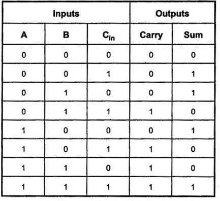
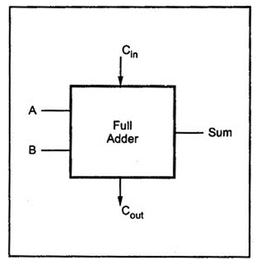
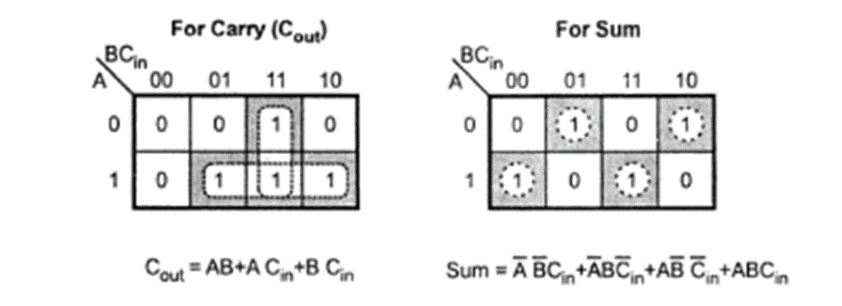
The boolean expression for Sum and Cout can be obtained using K-Maps as shown below:
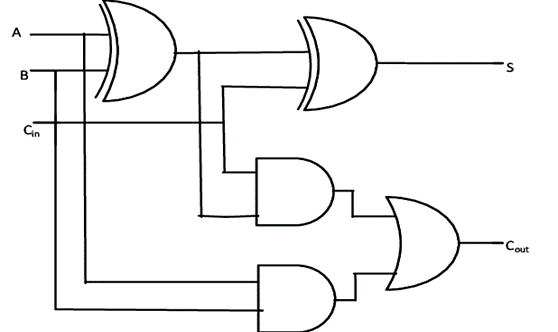
A Full-adder can therefore be realized as follows:
THE HALF SUBTRACTOR
A half-subtractor is a combinational circuit that subtracts two bits and produces their difference. It also has an output to specify if a 1 has been borrowed. Let us designate minuend bit as A and subtrahend bit as B. The result of the operation A-B produces two outputs, Difference (D) and Borrow (B) as shown below:

From the truth table, the Boolean expression for DIFFERENCE and BORROW can be written as:
DIFFERENCE = A  B
B
BORROW =  B
B
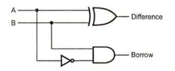
A half-Subtractor can therefore be realized as shown below:
THE FULL-SUBTRACTOR
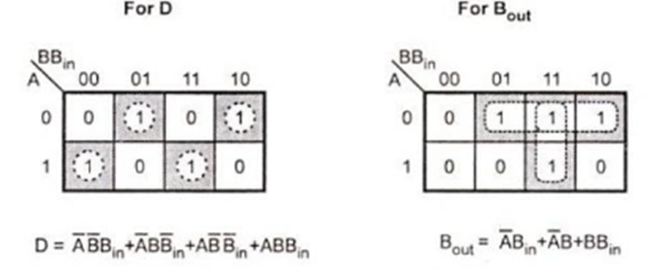
A half-subtractor can only be used for LSB subtraction. If there is a borrow during the subtraction of the LSB’s, it affects the subtraction in the next higher column; the subtrahend bit is subtracted from the minuend bit, considering the borrow from that column used for the subtraction in the preceeding column. Such a subtraction is performed by a full-subtractor. It subtracts one bit B from another bit Awhen already there is a borrow Bin from this column for the subtraction in the preceeding column, and outputs the difference bit and (D) and Borrow bit(Bout) required from the next column. Truth table of full adder is shown below:
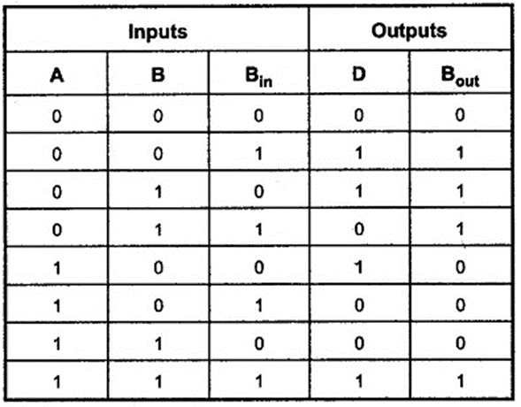
The boolean expression for Difference D and Bout can be obtained using K-Maps as shown below:
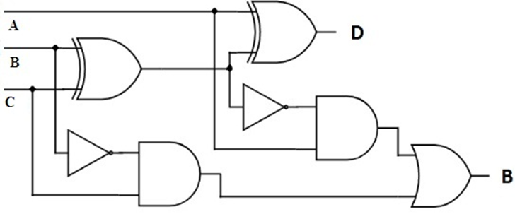
A Full-subtractor can therefore be realized as follows:
(II) BCD TO 7-SEGMENT DECODER
In most practical applications, seven segment displays are used to give a visual indication of the output states of digital IC’s such a decade counters, latches etc. For using this display device, the data has to be converted from some binary code to the code required for the display. Usually, the binary code used is natural BCD.
The following figure shows the display device and the segments which must be illuminated for each of the numerals.

The display system can be connected as follows:
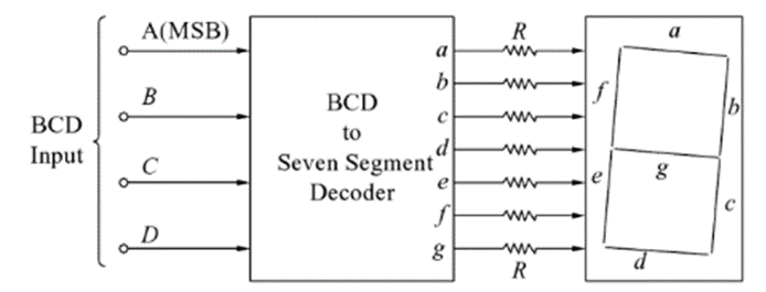
Here, ABCD is the natural BCD code for numerals 0 through 9. Following is the truth table of BCD to 7-segment decoder
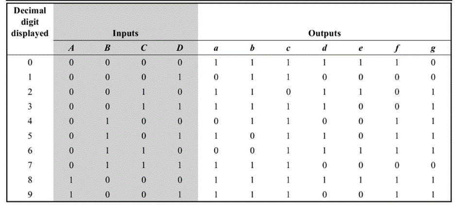
The K-Maps for each of the outputs A through G are given below:
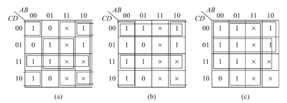
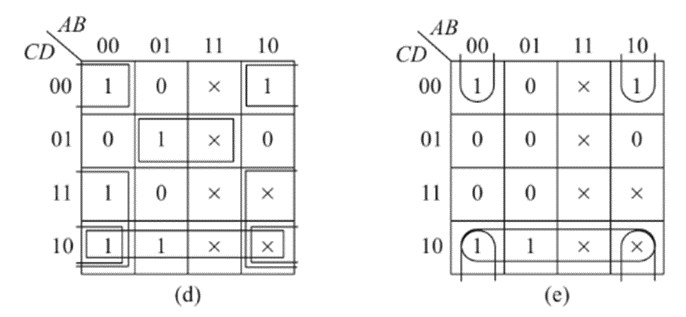
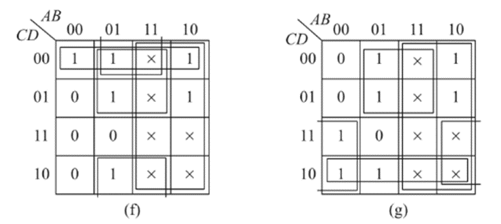
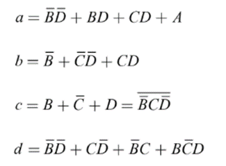
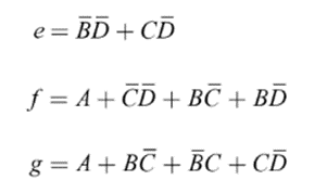
The simplified expressions obtained from the k-maps are:
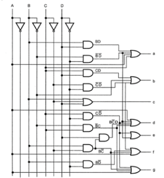
Logic diagram:
(III) CODE CONVERTERS
BINARY TO GRAY CODE CONVERTER
Gray Code system is a binary number system in which every successive pair of numbers differs in only one bit. It is used in applications in which the normal sequence of binary numbers generated by the hardware may produce an error or ambiguity during the transition from one number to the next.
The logical circuit which converts the binary code to equivalent gray code is known as binary to gray code converter.
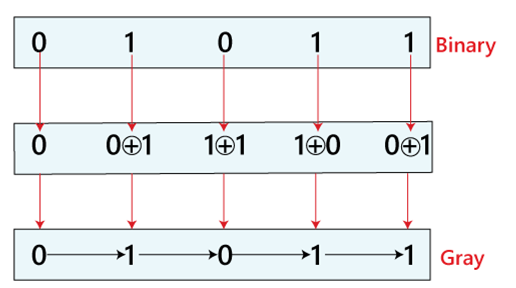
How to Convert Binary to Gray Code
The truth table of a 4 bit binary to Gray code converter is shown below:
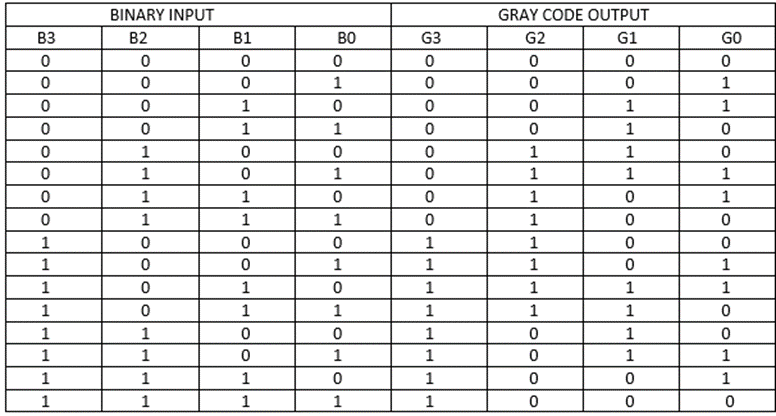
The simplified expressions for the outputs can be obtained using K-Maps:
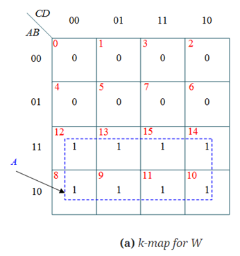
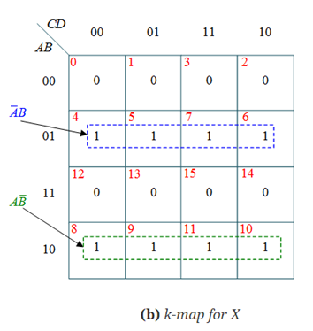
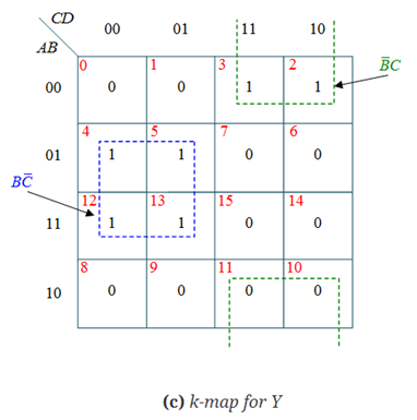
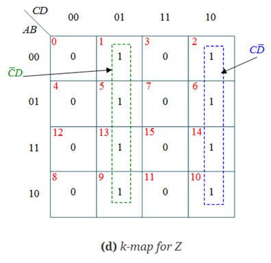
Therefore, W= A
X = AB’ +A’B =A B
B
Y = B’C +C’B = B C
C
Z = C’D +CD’ = C D
D
The logic circuit diagram can be realized as follows:
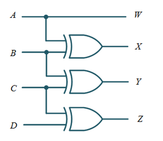
GRAY TO BINARY CODE CONVERTER
The logical circuit which converts the gray code to equivalent binary code is known as gray to binary code converter.
How to Convert Gray to Binary Code
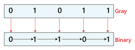
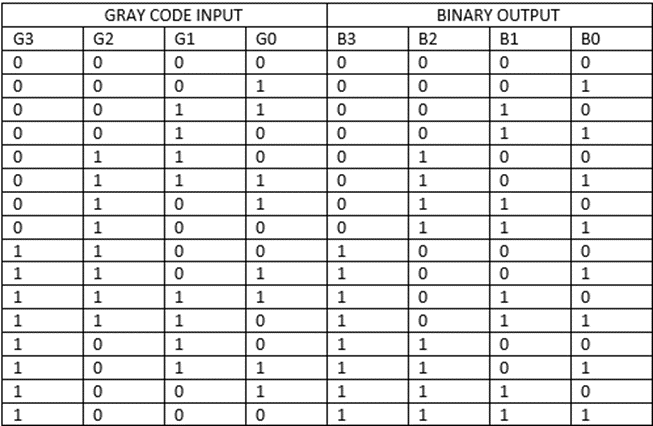
The truth table of a 4 bit Gray to Binary code converter is shown below:
The simplified expressions for the outputs can be obtained using K-Maps:
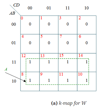
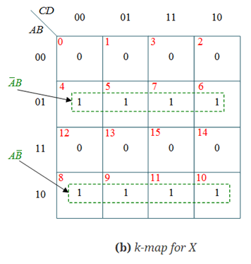
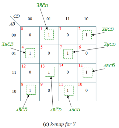
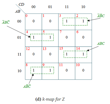
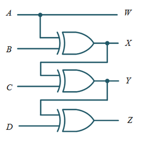
Therefore, W=A
X = AB’ +A’B =A B
B
Y = X C
C
Z = Y D
D
The logic circuit diagram can be realized as follows:
K-Map is a convenient method for minimizing Boolean functions up to 5 variables. But, it is difficult to simplify the Boolean functions having more than 5 variables by using this method.
Quine-McCluskey tabular method is a tabular method based on the concept of prime implicants. We know that prime implicant is a product or sum term, which can’t be further reduced by combining with any other product or sum terms of the given Boolean function.
This tabular method is useful to get the prime implicants by repeatedly using the following Boolean identity.
xy + xy’ = xy+y′y+y′ = x.1 = x
Procedure of Quine-McCluskey Tabular Method
Follow these steps for simplifying Boolean functions using Quine-McCluskey tabular method.
Step 1 − Arrange the given min terms in an ascending order and make the groups based on the number of one’s present in their binary representations. So, there will be at most ‘n+1’ groups if there are ‘n’ Boolean variables in a Boolean function or ‘n’ bits in the binary equivalent of min terms.
Step 2 − Compare the min terms present in successive groups. If there is a change in only one-bit position, then take the pair of those two min terms. Place this symbol ‘_’ in the differed bit position and keep the remaining bits as it is.
Step 3 − Repeat step2 with newly formed terms till we get all prime implicants.
Step 4 − Formulate the prime implicant table. It consists of set of rows and columns. Prime implicants can be placed in row wise and min terms can be placed in column wise. Place ‘1’ in the cells corresponding to the min terms that are covered in each prime implicant.
Step 5 − Find the essential prime implicants by observing each column. If the min term is covered only by one prime implicant, then it is essential prime implicant. Those essential prime implicants will be part of the simplified Boolean function.
Step 6 − Reduce the prime implicant table by removing the row of each essential prime implicant and the columns corresponding to the min terms that are covered in that essential prime implicant. Repeat step 5 for Reduced prime implicant table. Stop this process when all min terms of given Boolean function are over.
Example: Simplify the function f=∑m(0,1,2,5,6,7,8,9,10,14) using the Quine-McCluskey Method.
Solution:
This function can be represented by the list of minterms given below:
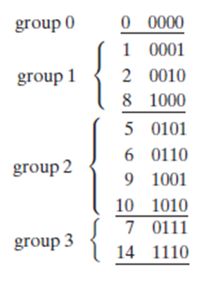
In this list, the term in group 0 has zero 1’s, group 1 terms have one 1, group 2 has two 1’s, and finally group 3 has three 1’s. Any two terms can be combined if the difference is only one variable. If two terms are compared in nonadjacent groups, there is no need for comparing as such terms will always differ in two variables; they also cannot be combined using XY + XY’ = X. Likewise, comparing terms within a group is not necessary because each term will have the same amount of 1’s and do not differ by at least two variables. So, terms in adjacent groups only need to be compared.
Always start with group 0. First, the group 0 term will be compared with all terms in group 1. The 0000 and 0001 terms can be combined to eliminate the fourth variable in both terms, which produces 000-. Comparably, 0 and 2 (0000 and 0010) combine to form 00-0 (or a’b’d’), and 0 and 8 (0000 and 1000) combine to form -000 (or b’c’d’). The resulting terms are listed in the table below.
No matter when two terms are combined, the corresponding decimal numbers differ by a power of 2. This statement holds true because when the binary representations differ in exactly one column. If these binary representations are subtracted, a difference of exactly 1 is found in the column in which the difference exists.
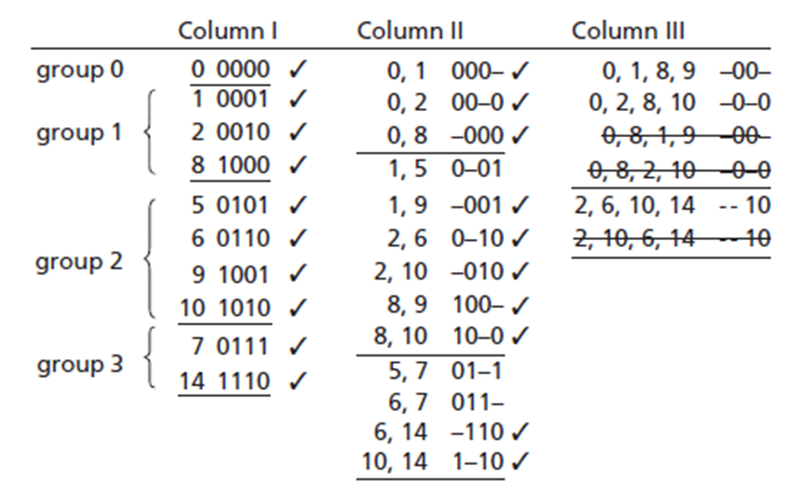
Comparing group 0 with group 2 or 3 is quite unnecessary because there will be a difference of more than one variable, thus proceeding to the next step of the method. When comparing term 1 (0001) in group 1 with all of group 2’s terms, terms 5 and 9 (0011 and 1001) can be combined but not 6 or 10 (0110 or 1010). The reduced terms (0-01 and -001) are moved to column II. Once a term has been combined with another term, a check is placed next to it, signifying that the term has been used in a simplification already. Likewise, term 2 in group can only combine with 6 and 10, and term 8 of group only combines with 9 and 10.
A term may be used to combine with another term more than once because X + X = X. If two terms have already been combined with other terms, they must still be compared and combined if possible. This is necessary to provide a preferred simplification of a minimum sum solution. To finish comparison in column I, all terms in groups 2 and 3 are compared and simplified if possible. By combining terms 5 and 7, 6 and 7, 6 and 14, and 10 and 14, new terms are placed in column II.
Just like in column I, the terms are divided amongst groups pertaining to the amount of 1’s in each term. Once again XY + XY’ = X is applied to find combinable pairs in column II. In this column the terms must have the same variables and the terms must differ by only one variable. First group terms in column II only need to be compared with terms in the second group which have dashes in the same place. The term 000- (terms 0 and 1 combined) can only be combined with the term 100- (terms 8 and 9 combined) to provide a combined term of -00-. This equates algebraically to a’b’c + ab’c’ = b’c’. This combined term is thus placed in column III denoted for 0,1,8,9 indicating that it was formed by comparing those minterms. Term (0, 2) can combine only with (8, 10) and the term (0, 8) with (1, 9) and (2, 10). Next, comparing terms in groups 2 and 3, (2, 6) can be combined and simplified with (10, 14), as well as (2, 10) with (6, 14). These terms can now be checked off in column II as they have been used to simplify the Boolean function.
The three terms left in column III are duplicate terms and were formed by combing the same set of four minterms in a different order. Since there are no further possible simplifications of any terms, the Quine-McCluskey process is complete. If there were more terms available for combinations, the comparison and simplification process would be continued, forming more groups and columns until all terms weren’t able to be combined.
Looking at chart, some terms have not been checked off; this is because they cannot possibly be combined with other terms, these terms are called prime implicants. Since every minterm has been included with at least one prime implicants, the function is now equal to the sum of its prime implicants.
f = a’c’d + a’bd + a’b’c + b’c’ + b’d’ + cd’
(1, 5) (5, 7) (6, 7) (0, 1, 8, 9) (0, 2, 8, 10) (2, 6, 10, 14)
The expression above has a minimum number of literals. A literal is a simple variable within a term which may or may not be complemented. The number of terms, however, is not minimum. By using the consensus theorem redundant terms can be eliminated as follows:
f = a’bd + b’c’ + cd’
This is minimal SOP expression for f.