Unit 5
State Machines
State Table
The state table representation of a sequential circuit consists of three sections labeled present state, next state and output. The present state designates the state of flip-flops before the occurrence of a clock pulse. The next state shows the states of flip-flops after the clock pulse, and the output section lists the value of the output variables during the present state.
State Diagram
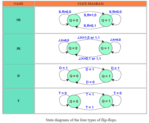
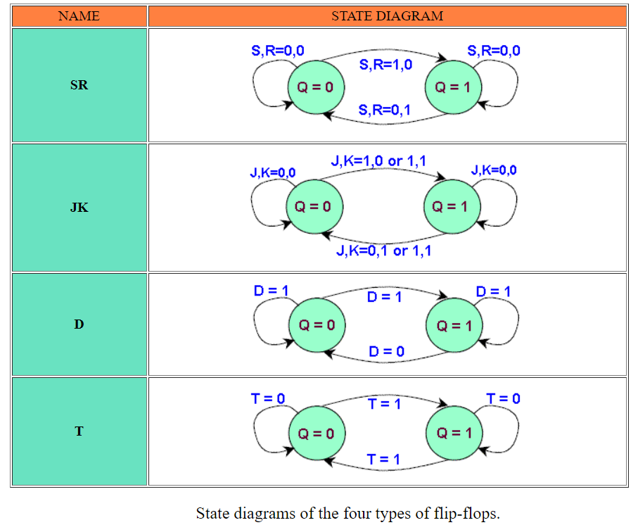
In addition to graphical symbols, tables or equations, flip-flops can also be represented graphically by a state diagram. In this diagram, a state is represented by a circle, and the transition between states is indicated by directed lines (or arcs) connecting the circles.
Mealy Machine
A Mealy Machine is an FSM whose output depends on the present state as well as the present input.
It can be described by a 6 tuple (Q, ∑, O, δ, X, q0) where −
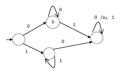
The state table of a Mealy Machine is shown below −
Present state | Next state | |||
input = 0 | input = 1 | |||
State | Output | State | Output | |
→ a | b | x1 | c | x1 |
b | b | x2 | d | x3 |
c | d | x3 | c | x1 |
d | d | x3 | d | x2 |
The state diagram of the above Mealy Machine is −
Moore Machine
Moore machine is an FSM whose outputs depend on only the present state.
A Moore machine can be described by a 6 tuple (Q, ∑, O, δ, X, q0) where −
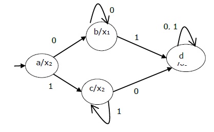
The state table of a Moore Machine is shown below −
Present state | Next State | Output | |
Input = 0 | Input = 1 | ||
→ a | b | c | x2 |
b | b | d | x1 |
c | c | d | x2 |
d | d | d | x3 |
The state diagram of the above Moore Machine is −
Mealy Machine vs. Moore Machine
The following table highlights the points that differentiate a Mealy Machine from a Moore Machine.
Mealy Machine | Moore Machine |
Output depends both upon the present state and the present input | Output depends only upon the present state. |
Generally, it has fewer states than Moore Machine. | Generally, it has more states than Mealy Machine. |
The value of the output function is a function of the transitions and the changes, when the input logic on the present state is done. | The value of the output function is a function of the current state and the changes at the clock edges, whenever state changes occur. |
Mealy machines react faster to inputs. They generally react in the same clock cycle. | In Moore machines, more logic is required to decode the outputs resulting in more circuit delays. They generally react one clock cycle later. |
Sequence detector
For non-overlapping case
Input :0110101011001
Output:0000100010000
For overlapping case
Input :0110101011001
Output:0000101010000
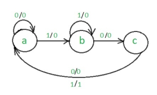
The steps to design a non-overlapping 101 Mealy sequence detector are:
Step 1: Development of the state diagram –
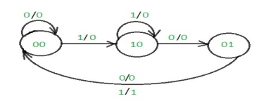
The state diagram of a Mealy machine for a 101 sequence detector is:
Step 2: Assignment of the code–
Rule 1: States having the same next states for a given input condition should have adjacent assignments.
Rule 2:States that are the next states to a single state must be given adjacent assignments.
Rule 1 given preference over Rule 2.
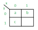
The state diagram after the code assignment is:
Step 3: Making Present State/Next State table –
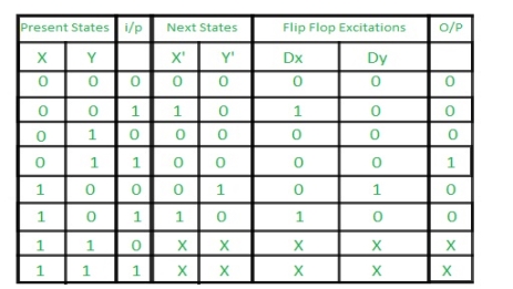
Step 4: Draw K-maps for Dx, Dy, and output (Z) –
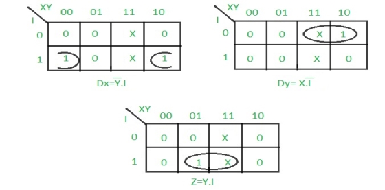
Step 5: Final implementation of the circuit –
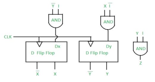
This is the desired circuit for a Mealy 101 non-overlapping sequence detector.
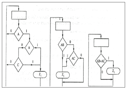
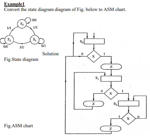
ASM stands for 'Algorithm State Machine 'or simply state machine is the another name given to sequential network is used to control a digital system which carries out a step by a step –by step procedure .It should be noted that ASM charts represent physical hardware and offers several advantages.
1. Operation of a digital system can be easily understand by inspection of the SM chart .
2. ASM charts represent physical hardware.
3. The ASM chart are equivalent to a state graph, and it leads directly to a hardware realization .
4. ASM charts can be described the operation of both combinational and sequential circuits .
5. ASM charts are easier to understand and can be converted several equivalent form.
6. The ASM chart may be equivalently expressed as a state and output table .
Following are the three basic components of ASM charts.
State box
State box is represented in rectangular shape. Each state box represents one state of the sequential circuit. The symbol of state box is shown in the following figure.
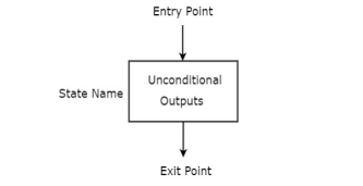
It is having one entry point and one exit point. Name of the state is placed to the left of state box. The unconditional outputs corresponding to that state can be placed inside state box. Moore state machine outputs can also be placed inside state box.
Decision box
Decision box is represented in diamond shape. The symbol of decision box is shown in the following figure.
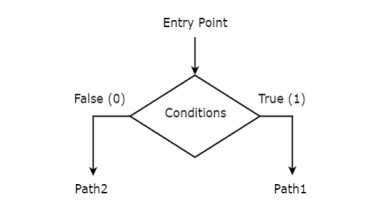
It is having one entry point and two exit paths. The inputs or Boolean expressions can be placed inside the decision box, which are to be checked whether they are true or false. If the condition is true, then it will prefer path1. Otherwise, it will prefer path2.
Conditional output box
Conditional output box is represented in oval shape. The symbol of conditional output box is shown in the following figure.
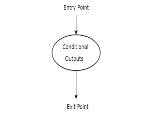
It is also having one entry point and one exit point similar to state box. The conditional outputs can be placed inside state box. In general, Mealy state machine outputs are represented inside conditional output box. So, based on the requirement, we can use the above components properly for drawing ASM charts.
Reference Books:
1. Anand Kumar, “Fundamentals of Digital Circuits”, Prentice Hall of India, 1st Edition.
2. J. F. Wakerly, “Digital Design- Principles and Practices,”, Pearson, 3rd Edition.
3. M. M. Mano, “Digital Design,” Prentice Hall India.