Unit II
Transient Analysis of RL, RC and RLC circuits
There are many reasons for studying initial (and final) conditions;
(i) The most important reason is that initial conditions must be known to evaluate the arbitrary constants that appear in the general solution of the differential equations
(ii) The initial conditions give knowledge of the behaviour of the elements at the instant of switching At reference time t=0, the switch is closed (we assume that switch act in zero time).
(iii) To differentiate between the time immediately before and immediately after the operation of a switch, we will use –ve and +ve signs. Thus conditions existing just before the switch is operated will be designated as i (0- ), v (0- ) etc. Conditions after as i (0+ ), v (0+ ) etc.
(iv) Initial conditions in a network depend on the past history of the network prior to t =0- and the network structure at t = 0+ , after switching.
(v) The evaluation of all voltages and currents and their derivatives at t = 0 + , constitutes the evaluation of initial conditions.
(vi) Sometimes we use conditions at t = ∞; these are known as final conditions
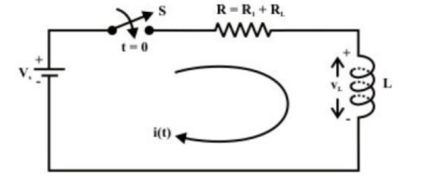
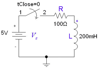
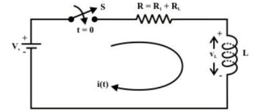
To find the current expression (response) for the circuit shown in fig. we can write the KVL equation around the circuit
vL(t) = L diL(t) /dt
ic(t) = C dvc(t) /dt
current through the capacitor
voltage across capacitor is given by
vc(t) = 1/ C  L(t) dt + iL (0) or
vc(t) = 1/C  dt + vc (0)
iL(t) = 1/L  L(t) dt + iL(0)
Consider network shown in fig. the switch k is moved from position 1 to 2 at reference time t = 0.
Now before switching take place, the capacitor C is fully charged to V volts and it discharges through resistance R. As time passes, charge and hence voltage across capacitor i.e. Vc decreases gradually and hence discharge current also decreases gradually from maximum to zero exponentially.
After switching has taken place, applying kirchhoff’s voltage law,
0 = VR + VC
Where VR is voltage across resistor and VC is voltage across capacitor.
VC = -VR = -i.R
i = C dVc/dt
VC = -R.C dVc(t)/dt
Above equation is linear, homogenous first order differential equation. Hence rearranging we have,
dt/RC = - dvc/Vc
Integrating both sides of above equation we have
t/RC = -ln Vc + k’
Now at t = 0, VC =V which is initial condition, substituting in equation we have,
0 = -ln V + k’
k’ = ln V
Substituting value of k in general solution we have
t/RC = -ln Vc + ln V
t/RC = ln (V/VC)
V/Vc = e t/RC
Vc = V e -t/RC
V = Q/C
Where Q is total charge on capacitor
Similarly, at any instant, VC = q/c where q is instantaneous charge.
So we have q/c = Q/C e -t/RC
q = Q e -t/RC
Thus charge behaves similarly to voltage across capacitor.
Now discharging current i is given by
i = Vc /R
but VR = Vc whe there is no source in circuit.
i = Vc/R
i = V/R e -t/RC
but VR = VC when there is no source in circuit.
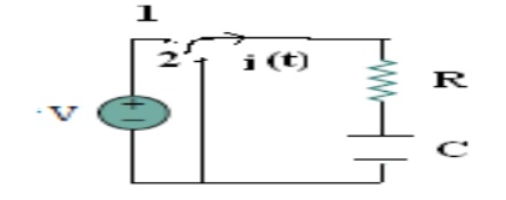
Consider network shown in fig. the switch k is moved from position 1 to 2 at reference time t = 0.
Now before switching take place, the capacitor C is fully charged to V volts and it discharges through resistance R. As time passes, charge and hence voltage across capacitor i.e. Vc decreases gradually and hence discharge current also decreases gradually from maximum to zero exponentially.
After switching has taken place, applying Kirchhoff’s voltage law,
0 = VR + VC -------------------------------------(1)
Where VR is voltage across resistor and VC is voltage across capacitor.
Vc = - VR = -i. R
i = C dvc/dt
Vc = -RC dvc/dt
Above equation is linear, homogenous first order differential equation. Hence rearranging we have,
Vc = -VR = -i.R
i = C. dvc/dt
Vc = -RC dvc/dt
t/RC = ln V/Vc
V/Vc = e t/RC
Vc = V e t/RC
V= Q/C
Where Q is total charge on capacitor
Similarly, at any instant Vc = q/c where q is the instantaneous charge
Therefore
q/c = Q/C e -t/RC
Therefore q = Q e -t/RC
Thus, charge behaves similarly to voltage across capacitor
Now discharging current is given by
i = Vc /R
but VR = Vc when there is no source in the circuit
i = Vc /R
i= V/R e-t/RC
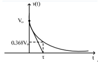
The above expression is nothing but discharge current of capacitor. The variation of this current with respect to time is shown in fig.
This shows that the current is exponentially decaying. At point P on the graph. The current value is (0.368) times its maximum value. The characteristics of decay are determined by values R and C, which are 2 parameters of network.
For this network, after the instant t = 0, there is no driving voltage source in circuit, hence it is called undriven RC circuit.
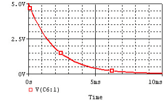
Current decay in source free series RL circuit: -
At t = 0- , switch k is kept at position ‘a’ for very long time. Thus, the network is in steady state. Initial current through inductor is given as,
iL = Io V/R = iL -------------------------------------(1)
Because current through inductor cannot change instantaneously
Assume that at t = 0 switch k is moved to position ‘b’,
Apply KVL
L di/dt + iR =0
L di/dt = -iR ------------------------------------(2)
Rearranging the terms in the above equation by separating variables
di/i = -R/L dt
Integrating on both sides with respect to the corresponding variables
ln i = -R/L -----------------------------------------------(3)
where k is constant of integration
To find k
From equation (1) at t=0 , i=Io
Substitute the values in eq(3)
ln io = -R/L -k’
k’ = ln Io -------------------------(4)
Substituting the value of k from eq (3)
ln i = -R/L t + ln io
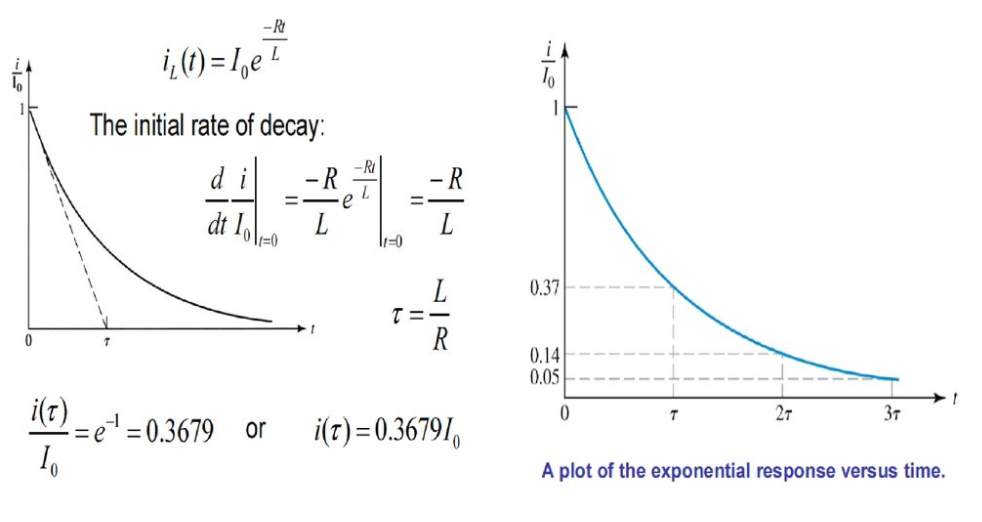
i/io = e-R/L t
i= io e-R/L t
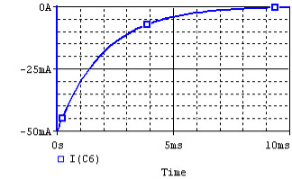
Fig shows variation of current I with respect to time.

From the graph, H is clear that current is exponentially decaying. At point P on graph. The current value is (0.363) times its maximum value. The characteristics of decay are determined by values R and L which are two parameters of network.
The voltage across inductor is given by
VL = L . di/dt = L . d/dt [ Io e -R/L t ] = L.Io (-R/L ) e -R/L t
VL = -Io . R e- R/L t
VL = -V e- R/L t volts

Charging
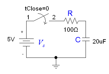
If the capacitor is initially uncharged and we want to charge it with a voltage source Vs in the RC circuit:
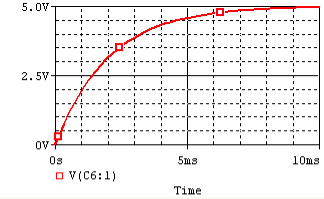
Current flows into the capacitor and accumulates a charge there. As the charge increases, the voltage rises, and eventually the voltage of the capacitor equals the voltage of the source, and current stops flowing. The voltage across the capacitor is given by:

where V0 = VS, the final voltage across the capacitor.
Discharging
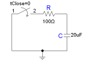
Consider the following circuit:
In the circuit, the capacitor is initially charged and has voltage V0 across it, and the switch is initially open. At time t = 0, we close the circuit and allow the capacitor to discharge through the resistor. The voltage across a capacitor discharging through a resistor as a function of time is given as:

where V0 is the initial voltage across the capacitor.
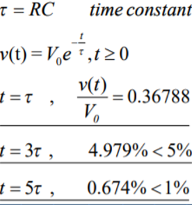
The term RC known as the time constant, which is a unit of time.
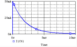
The function completes 63% of the transition between the initial and final states at t = 1RC, and completes over 99.99% of the transition at t = 5RC.
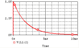
The voltage and current of the capacitor in the circuits above are shown in the graphs below, from t=0 to t=5RC.
Capacitor | ||
| Voltage | Current |
Charge | ||
Discharge | ||
Charging
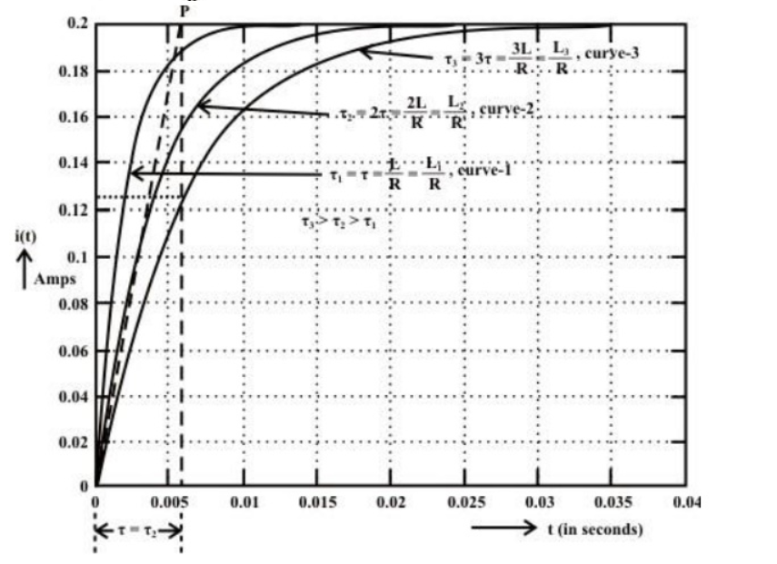
If the inductor is initially uncharged then charge it by inserting a voltage source Vs in the RL circuit:
The inductor initially has high resistance, as energy builds up a magnetic field. Once the magnetic field is up and no longer changing, the inductor acts like a short circuit.
The current at steady state is equal to I0 = Vs / R. Since the inductor is acting like a short circuit at steady state, the voltage across the inductor then is 0. The current through the inductor is given by:
iL(t) = Io (1- e -R/L t)
Discharging
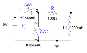
Consider the figure shown below were the inductor initially has current I0 = Vs / R flowing through it, replace the voltage source with a short circuit at t = 0.
After we cut out the voltage source, the voltage across the inductor is I0 * R, but the higher voltage is now at the negative terminal of the inductor.
Thus, I0 = − V / R. The current flowing through the inductor at time t is given by:

where I0 = − Vs / R.
The time constant for the RL circuit is equal to L / R.
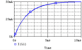
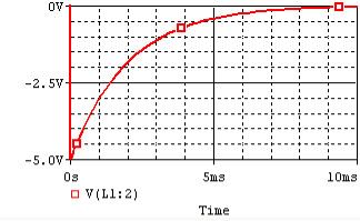
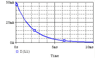
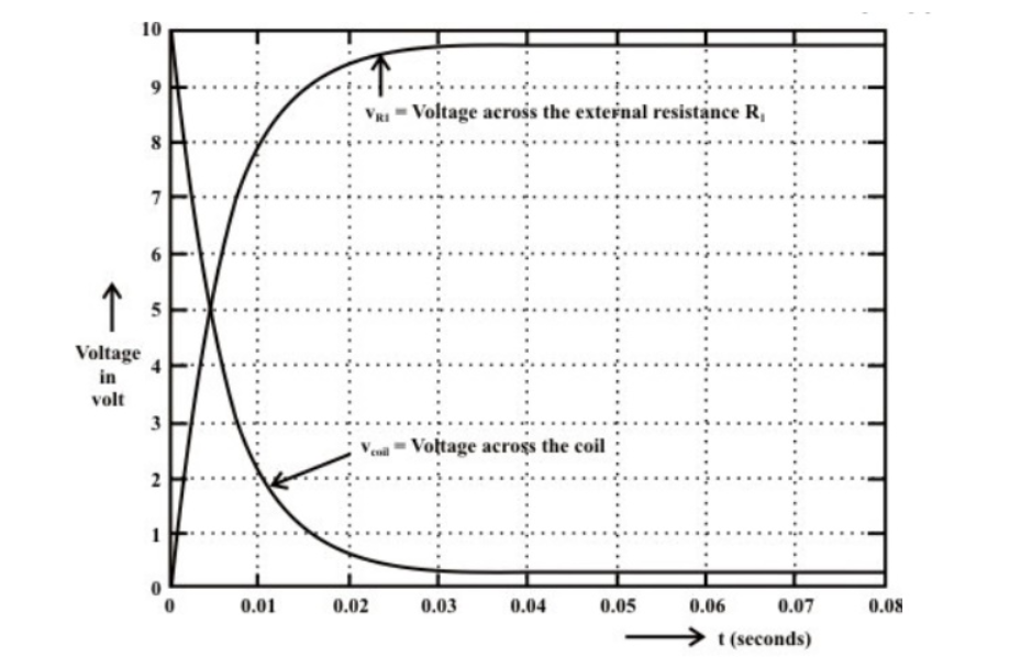
The voltage and current of the inductor for the circuits above are given by the graphs below, from t=0 to t=5L/R.
Inductor | ||
| Voltage | Current |
Charge | ||
Discharge | ||
The natural response is due to the initial condition of the storage component (C or L)
The forced response is resulted from external input.
Natural response
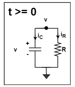
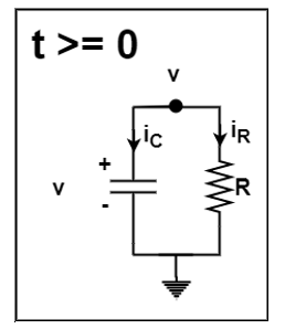
From nodal analysis
ic + iR =0
C dv/dt + 1/R .v =0
Characteristic root S,
CS + 1/R =0
S = -1/RC
Therefore v(t) = K e -1/RC t , t ≥ 0
From the initial condition v(0+) – v(0-) = Vo
v(t) = Vo e -t/RC

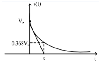
iR(t) = v(t) /R = Vo/R e -t/ τ ; t ≥0
The power dissipated in R is
p(t) = v iR = Vo2 / R e -2t/ τ
wR(t) =  dt = ½ CVo 2 ( 1- e 2t/τ)
wR(∞) = ½ CVo 2

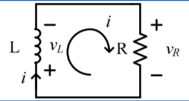
Mesh analysis
vL + vR =0
L di/dt + Ri =0
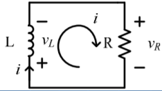
Characteristic equation
LS + R =0
S = -R/L
i(t) = K e – R/L t ; t ≥0
i(0+) = i(0-) = Io
i(t)= Io e -t/τ ; t ≥0
τ= L/R = time constant
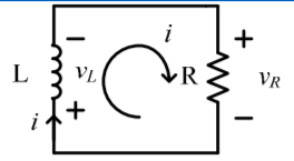
vR(t) = R I = Io R e -t/τ
pR = vRi = Io 2 R e -2t/τ
wR(t) =  R (t) dt = ½ L Io 2 (1- e -2t/τ)
wR(∞) = ½ LIo2
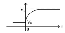
Forced response

RC dv/dt + v = Vs , t≥0
Solving for differential equation
(a) Homogeneous solution
RC dvh/dt + vh =0
vh(t) = K e -t/RC for t ≥0
(b) Particular solution
RC dvp/dt + vp = Vs
vp = Vs
complete solution + initial condition
v(t) = vh + vp
= K e -t/RC + Vs
v(0+)= v(0-) = Vo
K = Vo -Vs
v(t) = Vo for t<0
Vs + (Vo -Vs ) e -t/τ for t≥0

Mesh analysis
L di/dt + RTH .i = VTH for t ≥0
i(0)=0

i(t) = ih(t) + ip(t)
The characteristic equation
LS + RTH =0
S = -RTH /L = -1 / τ
ih(t) = K e -t/τ
ip(t) = VTH /RTH
i(t) = VTH /RTH + K e -t/τ
i(0+) = i(0-) =0
L is an equivalent open circuit
i(t) = VTH /RTH (1- e -t/τ ) , t ≥0
V(t) = L di/dt = VTH e -t/τ u(t)

The solution of the source-free series RLC circuit is called natural response of the circuit. The circuit is excited by the energy initially stored in the capacitor and inductor.
d 2 i / dt 2 + R/L di/dt + i/LC =0
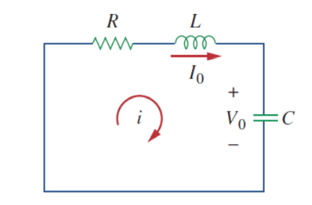
For capacitor v(0) = v(0+) = v(0-) = Vo
For inductor i(0) = i(0+) = i(0-) = Io
Initial conditions i(0) = Io
v(0) = 1/C  dt = Vo
R . di/dt + L d2 i/dt2 +i/C =0
d2i/dt 2 + R/L di/dt + i/LC =0
We get the initial value of the derivative of I from equation after KVL that is
R i(0) + L di(0)/dt + v(0) =0
R Io + L di(0) /dt + vo =0
di(0)/dt = -1/L (Rio + Vo)
i(0) = Io
In first order circuits the solution is Io e -t/τ . So we let i = A e st where A and s have to be determined
d 2 i / dt 2 + R/L di/dt + i/LC =0
A s2 e st + AR/L s est + A e st /LC =0
A est( s2 + R/L s + 1/LC) =0
s 2 + R/L s + 1/LC =0
-R/L ±  2 – 4/LC /2 = -R/2L ±
  2 – 1/LC
s 1 = -α +  α 2 – wo 2
s 2 = = -α +  α 2 – wo 2
α = R/2L
wo = -1/
s2 + α s + wo 2 =0
i(t) = A1 e s1t + A2 e s2 t
For the case of the series RLC circuits these two parameters are given by
α=R/2L and wo = 1/ 
The damping ratio is defined as the ratio of these two

In case of series RLC circuit the damping ratio is given by

The value of the damping factor determines the type of transient that the circuit will exhibit.
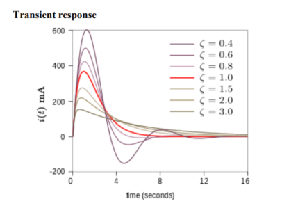
The overdamped response 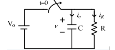 > 1
> 1
The underdamped response is 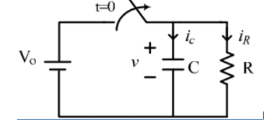 <1
<1
By applying standard trigonometric identities the two trigonometric functions may be expressed as a single sinusoid with phase shift,
The underdamped response is a decaying oscillation at frequency wd . The oscillation decays at a rate determined by the attenuationα. The exponential α in describes the envelope of the oscillation. B1 and B2 (or B3 and the phase shift in the second form) are arbitrary constants determined by boundary conditions. The frequency is given by
This is called the damped resonance frequency or the damped natural frequency. It is the frequency the circuit will naturally oscillate at if not driven by an external source. The resonance frequency wo, which is the frequency at which the circuit will resonate when driven by an external oscillation, may often be referred to as the undamped resonance frequency to distinguish it.
References:
1. Electric Circuits and Networks Textbook by Suresh Kumar
2. Schaum's Outline of Electric Circuits Textbook by Joseph A Edminister and Mahmood Nahvi
3. Introduction to Electric Circuits Book by James A. Svoboda and Richard C. Dorf
4. Electrical Circuits and Systems: An Introduction for Engineers and Physical ...Book by A. Howatson
