Unit V
AC Motors Single phase and three phase
The three phase induction motors are the most widely used electric motors in the industry.
They run at essentially constant speed from no-load to full-load. However, the speed is frequency dependent and consequently, these motors are not easily adapted to speed control.
Construction of Three Phase Induction Motor:
Figure shows the construction of three phase induction motor. A three phase induction motor has two main parts (i) stator and (ii) rotor.
The rotor is separated from the stator by a small air-gap which ranges from 0.4 mm to 4 mm, depending on the power of the motor.
1. Stator:
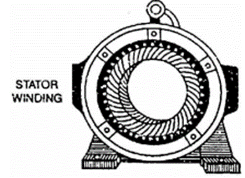
It consists of a steel frame which encloses a hollow, cylindrical core made up of thin laminations of silicon steel to reduce hysteresis and eddy current losses. A number of evenly spaced slots are provided on the inner periphery of the laminations.
The insulated connected to form a balanced 3-phase star or delta connected the circuit. The 3-phase stator winding is wound for a definite number of poles as per requirement of speed.
Greater the number of poles, lesser is the speed of the motor and vice-versa.
When 3-phase supply is given to the stator winding, a rotating magnetic field of constant magnitude is produced. This rotating field induces currents in the rotor by electromagnetic induction.
2. Rotor:
The rotor, mounted on a shaft, is a hollow laminated core having slots on its outer periphery. The winding placed in these slots (called rotor winding) may be one of the following two types:
(i) Squirrel cage type (ii) Wound type
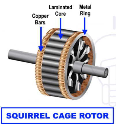
(i) Squirrel cage rotor: It consists of a laminated cylindrical core having parallel slots on its outer periphery.
One copper or aluminium bar is placed in each slot. All these bars are joined at each end by metal rings called end rings.
This forms a permanently short circuited winding which is indestructible. The entire construction (bars and end rings) resembles a squirrel cage and hence the name.
The rotor is not connected electrically to the supply but has current induced in it by transformer action from the stator.
Those induction motors which employ squirrel cage rotor are called squirrel cage induction motors.
Most of 3 phase induction motors use squirrel cage rotor as it has a remarkably simple and robust construction enabling it to operate in the most adverse circumstances.
However, it suffers from the disadvantage of a low starting torque .It is because the rotor bars are permanently short-circuited and it is not possible to add any external resistance to the rotor circuit to have a large starting torque.

(ii) Wound rotor: It consists of a laminated cylindrical core and carries a 3-phase winding, similar to the one on the stator.
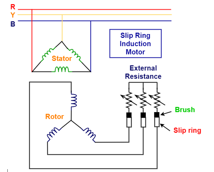
The rotor winding is uniformly distributed in the slots and is usually star-connected. The open ends of the rotor winding are brought out and joined to three insulated slip rings mounted on the rotor shaft with one brush resting on each slip ring.
The three brushes are connected to a 3-phase star-connected rheostat as shown in Figure. At starting, the external resistances are included in the rotor circuit to give a large starting torque.
These resistances are gradually reduced to zero as the motor runs up to speed.
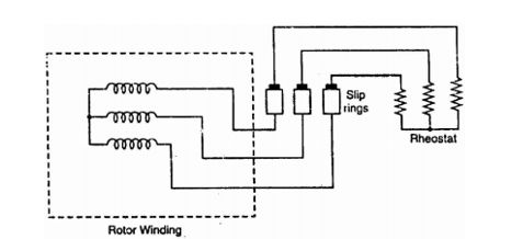
The external resistances are used during starting period only. When the motor attains normal speed, the three brushes are short-circuited so that the wound rotor runs like a squirrel cage rotor.
Types of Induction Motor:
Three phase motors are classified mainly in two categories based on the rotor winding (Armature coil winding) that is squirrel cage and slip ring (wound rotor motor).
Slip-ring or Wound Rotor Induction Motor
Slip: The ratio of slip speed to synchronous speed is known as slip s.
Effect of Slip on Rotor Parameters:
The frequency of induced e.m.f. in rotor is no longer same as that of stator voltage. Slip affects the frequency of rotor induced e.m.f.
Due to this some other rotor parameter also get affected.
1. Rotor frequency
2. Magnitude of rotor induced e.m.f.
3. Rotor reactance
4. Rotor power factor and
5. Rotor current
1. Effect of slip on rotor frequency: The frequency of rotor induced e.m.f. in running condition (fr) is slip times the supply frequency (f)
fr = sf
2.Effect of slip on rotor induced e.m.f.: The magnitude of the induced e.m.f in the rotor also reduces by slip times the magnitude of induced e.m.f. at standstill condition.
E2r = sE2
3. Effect of slip on rotor reactance: The resistance as independent of frequency remains same at standstill and in running condition. While the rotor reactance decreases by slip times the rotor reactance at standstill.
X2r = sX2
Z2r = [ R2 2 + X2r 2 ] ½ = [ R2 2 + (sX2) 2 ] ½
4.Effect of slip on rotor power factor: The power factor of rotor in running condition is,
cos ɸ 2r = R2 / Z 2r = R2/ [ R2 2 + (sX2) 2] ½
5. Effect of slip on rotor current: The rotor current in running condition is,
I2r = E2r/Z2r = sE2 / [ R2 2 + (sX2) 2 ] ½
The torque produced in the induction motor depends on the following factors :
1. The part of rotating magnetic field which reacts with rotor and is responsible to produce induced e.m.f. in rotor.
2. The magnitude of rotor current in running condition.
3. The power factor of the rotor circuit in running condition.
Mathematically the relationship can be expressed as,
T α ɸ I2r cos ɸ2r ------------------------(1)
where Φ = Flux responsible to produce induced e.m.f.
I2r = Rotor running condition and
cos Φ2r = Running p.f. of motor
The flux Φ produced by stator is proportional to i.e. stator voltage.
ɸ α E1 -------------------------------------(2)
While E1 and E2 are related to each other through ratio of stator turns to rotor turns i.e. K.
E2/E1 = K ------------------------------------------------(3)
Using (3) in (2) we can write
ɸ α E2 -------------------------------------(4)
Thus in equation(1) ɸ can be replaced by E2
T α E2 I 2r cos ɸ2r
Putting the value of I 2r cos ɸ2r
T α E2. sE2/ [ R2 2 + (sX2) 2 ] ½ . R2 / [ R2 2 + (sX2) 2 ] ½
T α sE2 2 R2 / [ R2 2 + (sX2) 2 ] ½
Where k = constant of proportionality
The constant k is for the three- phase induction motor.
k = 3/ 2π ns where ns = speed in rps .
From the torque equation, it is clear that torque depends on slip at which motor is running.
Hence while finding the condition for maximum torque, remember that the only parameter which controls the torque is slip s.
Mathematically for the maximum torque we can write,
dT/ds =0
d/ds [ k sE2 2 R2 / [ R2 2 + (sX2) 2 ] =0
[ R2 2 + (sX2) 2 ] . (kE2 2 R2 ) - (k s E2 2 R2 ) (2sX2 2 ) / [ R2 2 + (sX2) 2 ] =0
[ R2 2 + (sX2) 2 ] . (kE2 2 R2 ) = k s E2 2 R2 ) (2sX2 2 ) / [ R2 2 + (sX2) 2 ]
[ R2 2 + (sX2) 2 ] = (2sX2 2 )
s = R2/X2
This slip at which torque is maximum is denoted as smT.
Magnitude of maximum torque
Tm = ksmT . E2 2 R2 / [ R2 2 + (R2/X2 . X2) 2 ]
Tm = kE2 2 / 2X2
From the expression of Tm, it can be observed that
1. It is inversely proportional to the rotor reactance.
2. It is directly proportional to the square of the rotor induced e.m.f. at standstill. 3. The most interesting observation is, the maximum torque is not dependent on the rotor resistance R2.
Starting torque is the torque produced by induction motor when it starts . We know that at the start the rotor speed N is zero
So slip s = Ns – N / Ns
The equation of starting torque is obtained by putting value s=1 in the equation of torque of the three phase induction motor.
T = E2 2 R2/ R2 2 + X2 2 x 3/ 2π ns . N-m
The starting torque is known as standstill torque.
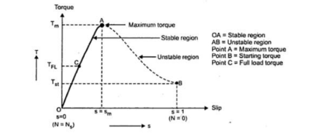
The curve obtained by plotting torque against slip from s = 1 (at start) to s = 0 (at synchronous speed) is called torque-slip characteristics of the induction motor. We have seen that for a constant supply voltage, E2 is also constant. So we can write torque equations as,
T α sR2/ R2 2 + (sX2) 2
Now to judge the nature of torque-slip characteristics let us divide the slip range (s = 0 to s = 1) into two parts and analyse them independently.
Low slip region : In low slip region, 's' is very very small. Due to this, the term (s X2) 2 is so small as compared to R2 2 that it can be neglected.
T α sR2 / R2 2 α s
Hence in low slip region torque is directly proportional to slip. So as load increases, speed decreases, increasing the slip. This increases the torque which satisfies the load demand. Hence the graph is straight line in nature.
High slip region : In this region, slip is high i.e. slip value is approaching to 1. Here it can be assumed that the term R2 2 is very very small as compared to (s X2) 2. Hence neglecting from the denominator, we get
T α sR2 / (sX2) 2 α 1/s
So, in high slip region torque is inversely proportional to the slip. Hence its nature is like rectangular hyperbola. Now when load increases, load demand increases but speed decreases.
As speed decreases, slip increases. In high slip region as T α1/s, torque decreases as slip increases.
Here range s = 0 to s = sm is called low slip region, known as stable region of operation. Motor always operates at a point in this region. And range s = sm to s = 1 is called high slip region which is rectangular hyperbola, called unstable region of operation.
Motor cannot continue to rotate at any point in this region.
Power Flow Diagram of Induction Motor explains the input given to the motor, the losses occurring and the output of the motor. The input power given to an Induction motor is in the form of three-phase voltage and currents. The Power Flow Diagram of an Induction Motor is shown below.
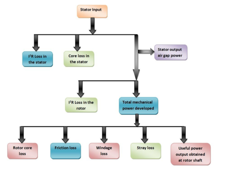
The power flow is given by the equation shown below.
Pis =  VL IL cos ɸi = 3 Vsp Isp cos ɸi
where cosϕi is the input power factor
The losses in the stator are
I2R losses in the stator winding resistances. It is also known as Stator copper losses.
PSCL = 3 I 2 sp R sp
Hysteresis and Eddy current losses in the stator core. These are known as Stator core losses.
PS(h+e)
The output power of the stator is given as
POS = Pis – PSC – PS(h+e)
This output power of the stator is transferred to the rotor of the machine across the air gap between the stator and the rotor. It is called the air gap Pg of the machine.
Thus,
The Power output of the stator = air gap power = input power to the rotor
POS = Pg= Pir
The losses in the rotor are as follows.
I2R losses in the rotor resistance. They are also called Rotor copper losses and represented as
Prc = 3 I2 2 R2
Hysteresis and eddy current losses in the rotor core. They are known as Rotor core losses.
Pr (h+e)
Friction and Windage losses Pfw
Stray load losses Pmisc, consisting of all losses not covered above, such as losses due to harmonic fields.
If the rotor copper losses are subtracted from rotor input power Pg, the remaining power is converted from electrical to mechanical form. This is called Developed Mechanical Power Pmd.
Developed Mechanical power = Rotor input – Rotor copper loss
Pmd = Pir – Prc or
Pmd = Pg – Prc
Pmd = Pg – 3 I2 2 R2
The output of the motor is given by the equation shown below.
Po = Pmd -Pfw-Pmisc
Po is called the shaft power or the useful power.
In the induction motor, efficiency is
Efficiency (η ) = Output/ Input = Output /output + losses
The total losses are losses in both stator and rotor, and mechanical losses.
The stator losses are iron or core loss and copper loss, i.e. loss in the stator winding resistance.
The core loss is the sum of hysteresis and eddy current losses, with the frequency in the stator
Both the above losses are related to frequency.
It may be noted here that the flux in the air gap is rated, as the input or supply voltage fed to the stator winding is rated with the frequency is also rated.
The copper loss is proportional to the square of the current in the stator winding. The loss in the rotor is only copper loss as shown earlier, with the iron loss being low due to low frequency in the rotor core.
For example, the rotor frequency ( fsfr = ) is only 2 Hz, if the slip is assumed as 4%, the speed being 1,440 rpm for a 4-pole motor. The line (input) frequency is 50 Hz. The iron loss is related to the frequency as stated earlier.
The net output available at the shaft is the gross output minus the mechanical losses.
The power flow diagram in an Induction motor, total input power fed to the motor via stator (winding) is IVP ,(cos3 IV ) i = φi
= where, V and I are the input voltage and current per phase, to the motor.
Total input power to the motor (stator) = Stator losses (iron & copper) + Total input power to the rotor (or Power transferred via air gap)
Total input power to the rotor = Rotor copper loss + Total output power (gross)
Total output power (gross) = Mechanical losses + Total output power (net) [or Power available at the shaft].
The induction motor consists of stator and rotor
Stator of Single -Phase Induction Motor
The stator of the single-phase induction motor has laminated stamping to reduce eddy current losses on its periphery.
The slots are provided on its stamping to carry stator or main winding. Stampings are made up of silicon steel to reduce the hysteresis losses.
When we apply a single phase AC supply to the stator winding, the magnetic field gets produced, and the motor rotates at speed slightly less than the synchronous speed Ns. Synchronous speed Ns is given by

Where,
f = supply voltage frequency,
P = No. of poles of the motor.
The construction of the stator of the single-phase induction motor is similar to that of three phase induction motor except there are two dissimilarities in the winding part of the single phase induction motor.
Rotor of Single -Phase Induction Motor
The construction of the rotor of the single-phase induction motor is similar to the squirrel cage three-phase induction motor. The rotor is cylindrical and has slots all over its periphery. The slots are not made parallel to each other but are a little bit skewed as the skewing prevents magnetic locking of stator and rotor teeth and makes the working of induction motor more smooth and quieter (i.e. less noisy).
The squirrel cage rotor consists of aluminum, brass or copper bars. These aluminum or copper bars are called rotor conductors and placed in the slots on the periphery of the rotor. The copper or aluminum rings permanently short the rotor conductors called the end rings.
To provide mechanical strength, these rotor conductors are braced to the end ring and hence form a complete closed circuit resembling a cage and hence got its name as squirrel cage induction motor. As end rings permanently short the bars, the rotor electrical resistance is very small and it is not possible to add external resistance as the bars get permanently shorted. The absence of slip ring and brushes make the construction of single- phase induction motor very simple and robust.
When we apply a single- phase AC supply to the stator winding of single phase induction motor, the alternating currents starts flowing through the stator or main winding. This alternating current produces an alternating flux called main flux. This main flux also links with the rotor conductors and hence cut the rotor conductors.
According to the Faraday’s law of electromagnetic induction , emf gets induced in the rotor. As the rotor circuit is closed one so, the current starts flowing in the rotor. This current is called the rotor current. This rotor current produces its flux called rotor flux. Since this flux is produced due to the induction principle so, the motor working on this principle got its name as an induction motor . Now there are two fluxes one is main flux, and another is called rotor flux. These two fluxes produce the desired torque which is required by the motor to rotate.
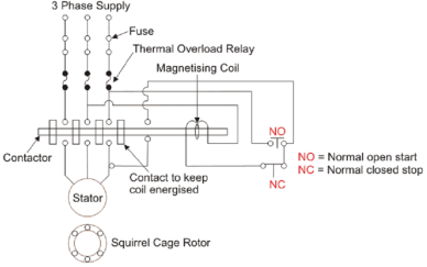
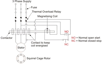
A wiring diagram of a DOL starter is shown below:
Since the DOL starter connects the motor directly to the main supply line, the motor draws high inrush current compared to the full load current of the motor (up to 5-8 times higher). The value of this large current decreases as the motor reaches its rated speed.
A direct on- line starter can only be used if the high inrush current of the motor does not cause an excessive voltage drop in the supply circuit.
If a high voltage drop needs to be avoided, a star delta starter should be used instead.
.
The equation for armature current in the motor.
Ia = (V-E)/Ra
The value of back emf (E) depends upon speed (N), i.e. E is directly proportional to N.
At starting, the value of E is zero. So, starting current is high.
In a small rating motor, the rotor has more considerable axial length and small diameter. So, it gets accelerated fastly.
Hence, speed increases and thus the value of armature current decreases rapidly. Therefore, small rating motors smoothly run when it is connected directly to a 3-phase supply.
If we connect a large motor directly across 3-phase line, it would not run smoothly and will be damaged, because it does not get accelerated as fast as a smaller motor since it has short axial length and larger diameter more massive rotor. However, for large -rated motors, we can use an oil immersed DOL starter.
DOL Starter Working Principle
The working principle of a DOL starter begins with the connection to the 3-phase main with the motor. The control circuit is connected to any two phases and energized from them only.
When we press the start button, the current flows through contactor coil (magnetizing coil) and control circuit also.
The current energises the contactor coil and leads to close the contacts, and hence 3-phase supply becomes available to the motor. The control circuit for a DOL Starter is shown below.
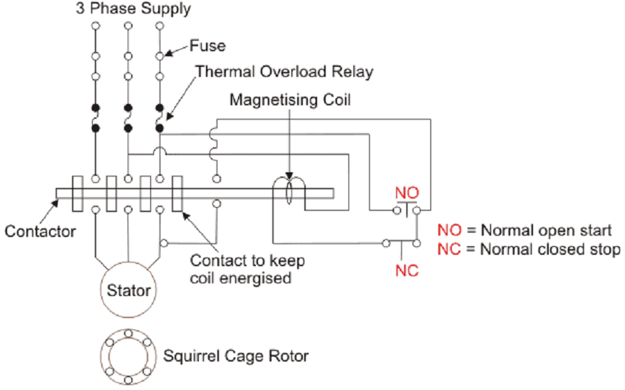
If we press the stop button, the current through the contact becomes discontinued, hence supply to the motor will not be available, and the similar thing will happen when the overload relay operates. Since the supply of motor breaks, the machine will come to rest.
The contactor coil (Magnetizing Coil) gets supply even though we release start button because when we release start button, it will get supply from the primary contacts as illustrated in the diagram of the Direct Online Starter.
Advantages of DOL Starter
The advantages of a DOL starter include:
Disadvantages of DOL Starter
The disadvantages of a DOL starter include:
DOL Starter Applications
The applications of DOL starters are primarily motors where a high inrush current does not because excessive voltage drop in the supply circuit (or where this high voltage drop is acceptable).
Direct on- line starters are commonly used to start small water pumps, conveyor belts, fans, and compressors. In the case of an asynchronous motor (such as the 3-phase squirrel-cage motor) the motor will draw a high starting current until it has run up to full speed.
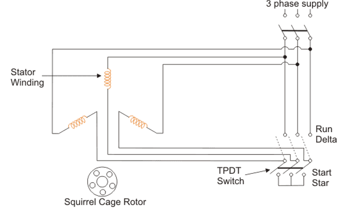
A star delta starter is a type of reduced voltage starter. It is used to reduce the starting current of the motor without using any external device or apparatus.
This is a big advantage of a star delta starter, as it typically has around 1/3 of the inrush current compared to a DOL starter.
The starter mainly consists of a TPDP switch which stands for Tripple Pole Double Throw switch.
This switch changes stator winding from star to delta. During starting condition stator winding is connected in the form of a star.
A star delta starter reduces the starting current of a three-phase induction motor.
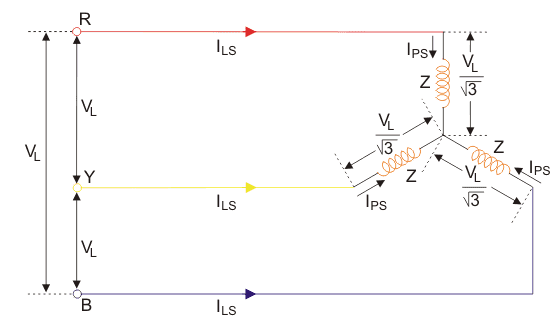
For that let us consider,
VL = Supply Line Voltage, ILS = Supply Line Current and, IPS = Winding Current per Phase and Z = Impedance per phase winding at stand still condition.
As the winding is star connected, the winding current per phase (IPS) equals to supply line current (ILS).
IPS = ILS
As the winding is star connected, the voltage across each phase of the winding is
VL/ 
Hence, the winding current per phase is
IPS = VL /  Z
Z
Since here, the winding current per phase (IPS) equals to the supply line current (ILS), we can write,
IPS = VL /  Z --- ILS = VL /
  Z
Z
Let us consider the situation where the motor gets started with delta connected stator winding from same three phase supply points,
Here, ILD = Supply Line Current and, IPD = Winding Current per Phase and Z = Impedance per phase winding at stand still condition.
As the winding is delta connected, supply line current (ILD) is root three times of the winding current per phase (IPD)
I LD =  I PD
I PD
As the winding is delta connected, the voltage across each phase of the winding is
VL
Hence, the winding current per phase is
IPD = VL /Z
Now, we can write,
ILD =  IPD =
IPD =  VL /Z
VL /Z
Now, by comparing supply line currents drawn by an induction motor with star and delta connected winding, we get
ILD / ILS =  VL /Z / VL /
  Z = 3 --- ILS = 1/3 ILD
Thus we can say that the starting current from the mains in case of star delta is one-third of direct switching in the delta. Again, the starting torque of an induction motor is proportional to the square of the voltage applied to the winding per phase.
Starting torque in star connected stator winding motor/ Starting torque in delta connected stator winding motor
= (VL /  ) 2 / VL 2 = 1/3
The equation shows that star delta starter reduces the starting torque to one-third of that produced by DOL starter. The star-delta starter is equivalent to an autotransformer with a 57.7% tapping.
Advantages of Star Delta Starter
The advantages of star delta starters include:
Disadvantages of Star Delta Starter
The disadvantages of star delta starters include:
Application of Star Delta Starter
The advantages and disadvantages, a star delta starter is most suited to applications where the required starting current is low and where the line current draw must be at a minimum value.
The star delta starter is not suitable for applications where high starting torque delivery is required. For these applications, a DOL starter should be used instead.
If the motor is too heavily loaded, there will not be enough torque to accelerate the motor upto speed before switching over to the delta position. Example application for a star delta starter is a Centrifugal compressor.
Variable Frequency Control is a method which is used to control the speed of an induction motor.
The synchronous speed and therefore, the speed of the motor can be controlled by varying the supply frequency.
The synchronous speed of an induction motor is given by the relation shown below.
Ns = 120f/P
The EMF induced in the stator of the induction motor is given by the equation shown below.
E1 = 4.44 kw1 f ɸ T1
Therefore, if the supply frequency is changed induced EMF will also change to maintain the same air gap flux. The terminal voltage V1 is equal to the induced EMF E1 if the stator voltage drop is neglected.
In order to minimise the losses and to avoid the saturation, the motor is operated at rated air gap flux. This condition is obtained by varying the terminal voltage with frequency so as to maintain (V/f) ratio constant at the rate value. This type of control is known as Constant Volts Per Hertz.
Thus, the speed control of an induction motor using variable frequency supply requires a variable voltage power source. The variable frequency supply is obtained by the following converters.
An inverter converts a fixed voltage DC to a fixed or variable voltage AC with variable frequency. Cyclo converter converts a fixed voltage and fixed frequency AC to a variable voltage and variable AC frequency.
The variable frequency control allows good running and transient performance to be obtained from a cage induction motor. Cyclo- converter- controlled induction motor drive is suitable only for large power drives and to get lower speeds.
The major applications of induction motors are in industries, lifts, hoists, lathe machines, textile etc. For efficiency, reliability, speed and torque, three phase induction motor comes into the picture. Speed control of such a machine is significant in variable load constant speed application.
References:
o Principles of Electric Machines and Power Electronics Book by P. C Sen
o Principle Of Electrical Machines Book by Rohit Mehta and V.K. Mehta
o Theory & Performance Of Electrical Machines Book by J. B. Gupta
o Electrical Machines Book by S. K. Bhattacharya